i
UNIVERSITI TEKNIKAL MALAYSIA MELAKA
DESIGN AND DEVELOPMENT OF ROAD PAINT ROBOT
USING GPS ALGORITHM
This report submitted in accordance with requirement of the Universiti Teknikal Malaysia Melaka (UTeM) for the Bachelor Degree of Engineering Technology
(Industrial Automation & Robotics) (Hons.)
by
SHAIKH UQHAILI ASH – QHALANI BIN SHAIK ISMAIL B071310699
940730-07-5021
ii
DECLARATION
I hereby, declared this report entitled “Design and Development of Road Paint Robot using GPS algorithm” is the results of my own research except as cited in
references.
Signature : ……….
Author’s Name : SHAIKH UQHAILI ASH-QHALANI BIN
SHAIK ISMAIL
Date : 9th DECEMBER 2016
iii
APPROVAL
This report is submitted to the Faculty of Engineering Technology of UTeM as a partial fulfillment of the requirements for the degree of Bachelor of Electrical Engineering Technology (Industrial Automation & Robotics) with Honours. The member of the supervisory is as follow:
………
(Mr. Mohamad Haniff bin Harun)
ABSTRAK
Robot mengecat jalan menggunakan algoritma GPS mempunyai fungsi lukisan garis tebal dan pecah penuh. Berbanding dengan mudah didapati manusia automatik mesin cat jalan raya yang memakan masa dan kecederaan yang berpotensi untuk pekerja, prototaip ini menyajikan cara yang lebih baik terutamanya dalam mengurangkan potensi kesilapan. Untuk projek ini, GPS digunakan untuk menetapkan jarak ruang bekerja untuk robot ke titik ia perlu dihentikan lukisan. Sensor ultrasonik akan dilampirkan di hadapan robot. Ini untuk memastikan ia dapat mengesan apa-apa halangan dan mengelakkan serta-merta. Ia dijangka bahawa robot ini boleh menjadi autonomi sepenuhnya menggunakan GPS dalam lukisan garis. Robot ini yang sedang dilakukan dalam prototaip kecil dilakukan dalam mengadakan sistem yang tertutup. Fungsinya yang menjadi kebimbangan utama. Apabila prototaip boleh dipercayai, ia boleh dipindahkan ke dalam keadaan jalan sebenar.
ABSTRACT
The GPS automated road paint robot has the functionalities of painting full solid and broken line. Compared to the readily available human automated road paint machine which are time consuming and potential injury for the workers, this prototype serves way better especially in reducing error potential. For this project, GPS is used to set the distance of working space for the robot to the point it has to stop painting. An ultrasonic sensor will be attached at the front of the robot. This to ensure it could detect any obstacle and avoid it instantly. It is expected that this robot could be fully autonomous using GPS in painting line. This robot is being done in a small scale prototype done in a closed set up system. Its function that is the main concern. Once the prototype could be reliable, it could be transferred into real road situation.
DEDICATION
To my beloved parents, I acknowledge my sincere indebtedness and gratitude to them for their love, dream and sacrifice throughout my life. Their sacrifice had inspired me from the day I learned how to read and write until what I have become now. I cannot find the appropriate words that could properly describe my appreciation for their devotion, support and faith in my ability to achieve my dreams
ACKNOWLEDGEMENT
First and foremost, all praise to Allah the Almighty for giving me the strength, health, knowledge and patience to successfully complete this Finale Year Project report in the given time. I would like to address my deepest appreciation to the supervisor, Mr. Mohamad Haniff bin Harun for his encouragement, comments, guidance and enthusiasm through the time developing the report. This project report might be impossible to complete without all of your help. Last but not least, thank you to everyone that directly and indirectly involved in helping me finishing this Finale Year Project report. Thank you.
TABLE OF CONTENTS
DECLARATION...i
APPROVAL...ii
ABSTRAK...iii
ABSTRACT...iv
DEDICATION...v
ACKNOWLEDGEMENTS...vi
TABLE OF CONTENTS...vii
LIST OF FIGURE...viii
LIST OF TABLES...ix
CHAPTER 1: INTRODUCTION ... xiii
1.0 Introduction ... xiii
1.1 Project Background ... xiii
1.2 Problem Statement ... xiv
1.3 Project Objective ... 3
1.4 Work Scope ... 4
CHAPTER 2 : LITERATURE REVIEW ... 5
2.0 Introduction ... 5
2.1 Microcontroller ... 5
2.2 Wireless Connection ... 7
2.3 Navigation System ... 9
2.3.1 Path Mapping ... 10
2.3.2 Simultaneous Localization and Path Mapping (SLAM) ... 13
2.4 Conclusion...…………...………..16
CHAPTER 3 : PROJECT METHODOLOGY………. ... 19
3.0 Introduction…...………...19
3.1 Work Flow...……...………20
3.2 Electrical Hardware……...………...20
3.2.1 Aduino Uno………..20
3.2.2 USB Micro B cable...………..24
3.2.3 GPS Module..………...25
3.2.4 Motor Driver..………...27
3.2.5 DC motor with gear....……….……….27
3.2.6 DC Servo Motor..…….………28
3.2.7 Ultrasonic Sensor...………30
3.2.7.1 Ultrasonic Sensor Working Principle…...………30
3.2.8 Lipo Battery……...………..………...32
3.2.9 Bluetooth Module....………...33
3.2.9.1 Bluetooth Module Operational………..………34
3.3 Design of Autonomous Road Paint Robot...………..…35
3.3.1 Mechanical Framework Design...………...36
3.3.2 Programming Framework Design...………...36
3.3.3 Electronic Framework Design...………..39
3.5 Overall System Operation...……….………..40
CHAPTER 4: RESULT AND DISCUSSION...…...………....42
4.0 Introduction...………...42
4.1 Experiment of load robot and speed...43
4.2 Experiment on ultrasonic range versus obstacles...………...45
4.3 Experiment of ultrasonic sensor angle of detection...46
4.4 Experiment of Bluetooth transmission...47
4.5 Experiment on GPS coordination...48
4.6 Road Line Painting Analysis...52
CHAPTER 5: DISCUSSION AND CONCLUSION………...55
5.0 Introduction...55
5.1 Conclusion...55
5.2 Recommendation...56
5.3 Future Investigation...57
REFERENCE……….………...59
APPENDIX A……….………..61
APPENDIX B……….…..69
APPENDIX C………...73
APPENDIX D………...79
LIST OF TABLES
3.1: Technical specification of Arduino Uno board...………...21
3.2: GPS module pin description………...……….. 24
3.3: Ultrasonic sensor HC - SR04 details………...………..28
4.1: Experiment of ultrasonic range versus obstacles...41
4.2: The edge recognition of the sensor...44
4.3: Time response for Bluetooth versus distance...46
LIST OF FIGURES
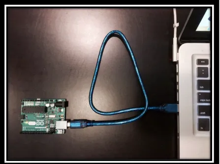
2.1: Arduino connect to PC………...……...………..4
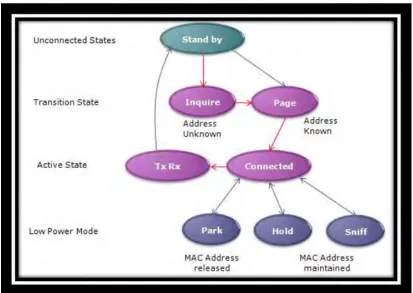
2.2: Bluetooth pairing and connection process………...………...5
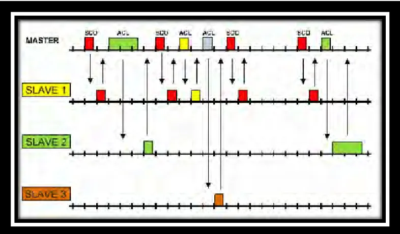
2.3: Inquiry Procedure...………...………...6
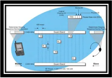
2.4: Bluetooth Operation Diagram………...……....7
2.5: Working Principle of Global Positioning System………...8
2.6: Navigation of mobile robot with same starting but different target locations...9
2.7: Navigation of mobile robot with different starting but same target locations...9
2.8: The robot path with Fast-SLAM algorithm when encountering shaped obstacles...12
2.9: Standard deviation with beacons………...……...…….14
2.10: Standard deviation with SLAM………...…………...14
2.11: Decreasing uncertainty in landmark location estimation………...…....16
3.1: Autonomous road paint robot block diagram………...17
3.2: The work flow of the autonomous road paint robot development…………...18
3.3: Arduino Uno board………...20
3.4: Arduino Leonardo Pinout Reference………...21
3.5: USB Micro B cable………...22
3.6: GPS module………...24
3.7: GPS module connection to Arduino………...24
3.8: Motor Driver………...25
3.6: DC motor with gear………...26
3.7: DC servo motor………...27
3.8: Variable Pulse width control servo position………...27
3.9: Ultrasonic sensor………...28
3.10: Principal of detecting object and measuring the distance………...29
3.11: 12V Lipo Battery………...30
3.12: Bluetooth HC-05 module………...………...31
3.13: Connection between Bluetooth and Arduino UNO………...33
3.14: Complete design of the autonomous road paint robot………...34
3.15: Basic GPS code in Arduino IDE………...36
4.1: Distance set in programming versus distance between obstacles and robot...42
4.2: Experiment of ultrasonic range versus obstacles...43
4.3: Experiment of angle versus object detection...45
4.4: Bluetooth time response versus distance...47
4.5: Console showing coordinate in the computer via bluetooth...48
4.6: Brief location mapping...49
4.7: Enhanced view of mapping...49
4.8: Solid line for straight path...50
4.9: Broken line for straight path...51
4.10: Solid line for 90 degrees cornering path...51
CHAPTER 1
INTRODUCTION
1.0 Introduction
This chapter provides an introduction about this project. It starts with general information and background about autonomous robot, problem statement and it also cover the objective, problem statement and scope for the project.
1.1 Project Background
The GPS automated road paint robot has the functionalities of painting full solid and broken line. Compared to the readily available human automated road paint machine which are time consuming and potential injury for the workers, this prototype serves way better especially in reducing error potential.
It is expected that this robot could be fully autonomous using GPS in painting line. This robot is being done in a small scale prototype done in a closed set up system. Its function that is the main concern. Once the prototype could be reliable, it could be transferred into real road situation.
1.2 Problem Statement
The current pavement sign marking operations are manually carried out, which are labor-intensive. This method requires blocking traffic for a long period of time resulting serious traffic jam. Also, the workers are exposed to possible injury and even death by passing traffic. The other main concern is that when it is manually carried out by human, the potential of error to be done is higher. Hence, an autonomous robot needs to be created to tackle all these problems. Therefore, a road paint robot using GPS algorithm is being created.
1.3 Project Objective
a) to develop an autonomous robot using Global Positioning System.
b) to design mechanical structure and electronics circuit control of autonomous robot using GPS.
c) to analyze the efficiency of the autonomous robot using GPS.
To fulfill the objectives, there are elements need to be considered:
a) Mechanical Scope : Mechanism used is two DC gear motor, L293D motor
driver and painting tank with valve using micro servo motor.
CHAPTER 2
LITERATURE REVIEW
2.0 Introduction
Before expressing any venture, a few thoughts from different scientists or different creators are exceptionally valuable. Thoughts and reviews from their examinations such as mechanical outline, control strategy, program improvement and technique. In this way, literature review is the starting stride to comprehend the thoughts to build up this versatile robot venture. In this section, point of interest rundowns of the portable robot advancement from past analysts are resolved and the present undertaking will be thought about and examined.
2.1 Microcontroller
based on the Processing venture, which incorporates support for C and C++ programming language. The Arduino shield are little print circuit sheets (PCB) to be connected to the highest point of the Arduino board, furthermore, which go about as an interface between the board and the outer world (e.g, with sensors) or expand the functionalities of the board itself. The Arduino firmware – By building onto the Arduino center library, we have executed an arrangement of configurable projects (on the other hand draws) for the microcontroller.
Figure 2.1: Arduino connect to PC
2.2 Wireless Connection
[image:22.612.165.525.342.593.2]In view of (Pan, Luo et al. 2012), Bluetooth correspondence depends on one of a kind MAC. Before utilizing Bluetooth correspondence, the Bluetooth gadget must be matched first. The associated gadget will be imparted together to a RFCOMM channel to transmit information. The Bluetooth correspondence is incorporate three stages, that Query Bluetooth, Finding Device and Connecting Bluetooth. In Query Bluetooth, to get the Bluetooth action and the strategy for an action result, we can utilize Bluetooth Adapter. Furthermore, is Finding Device step, we have to open MAC location and Bluetooth client name to combine the Bluetooth and the last stride is interfacing the Bluetooth with gadget. The procedure of blending association is appeared in Figure 2.2.
Figure 2.2: Bluetooth pairing and connection process
expert. Without the piconet creation, the correspondence between two gadgets can't happen. There are two stages in piconet creation that is request process and the page procedure. Request procedure is the place an expert gadget finds neighboring slave gadgets, and the page procedure is the place association between them sets up. The Bluetooth Baseband Specification, have characterized that there are three stage of strategy happen in Bluetooth point to point association. To start with neighborhood data is gathered through the Inquiry Procedure. A Paging Procedure might be accordingly used to build up associations between neighbouring gadgets, while in the last stage piconet properties are arranged upon. Both the Inquiry and Paging methods are unbalanced procedures. Amid Inquiry, transmitting hubs find and gather neighbourhood data gave by reacting hubs that are in an Inquiry Scan state. Figure 2.3 and 2.4 demonstrates the Inquiry Procedure Bluetooth operation outline.
Figure 2.4: Bluetooth Operation Diagram
2.3 Navigation System