LINEAR STOCHASTIC EVALUATION OF TYRE VIBRATION
DUE TO TYRE/ROAD EXCITATION
E Rustighi1, S J Elliott1, S Finnveden2, K Gulyás3, T Mócsai3, and M Danti4
1Institute of Sound and Vibration Research, University of Southampton
Highfield, Southampton, SO17 1BJ, UK er@isvr.soton.ac.uk
2MWL, Aeronautical and Vehicle Engineering, KTH, Stockholm, Sweden
3Budapest University of Technology and Economics, Budapest, Hungary
4Centro Ricerche FIAT, Torino, Italy
ABSTRACT
1 INTRODUCTION
Nowadays, because of the development of more silent vehicle power units, the main source of internal and external car noise is the interaction between tyre and road [1], [2]. Such an interaction is non-linear because of the time-varying nature of the contact area. Deterministic models [3], that try to model the physical processes involved, have been used to predict the noise. Even though these can be very detailed, they are still numerically very onerous and not yet very reliable since not all the processes that take place are fully understood. Hybrid models [4] apply deterministic model in order to represent the contact mechanism and rely on empirical analysis in order to find data correlations between road characteristics and the car noise. These models have the disadvantage of needing a large amount of experimental data to be reliable and still rely on deterministic model of the non-linear contact.
In this paper a fully 3D linear model is presented for the random excitation of a tyre’s vibration and its subsequent sound radiation. Rustighi and Elliott [5] already illustrated this methodology on a simpler 2D model, and also investigated the feasibility of actively controlling the tyre vibrations.
2 3D ROAD/TYRE MODEL
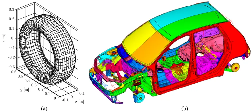
A common car tyre has been meshed with quadratic anisotropic, doubly curved deep shell elements that includes in-plane pre-stress for the belt and quadratic, Lagrange type, isotropic two-dimensional elements for the tread. The tyre mesh is shown in Fig. 1. The motion of the air inside the tyre cavity has been accounted for by linear triangular fluid elements. The flexibility matrix for such a smooth, stationary tyre was calculated with a vibration model based on a linear waveguide finite element method, showing to be in excellent agreement with measurements, except for a 2.5 dB deviation around 700 Hz [6]. In fact, at this frequency the transverse shearing of the belt becomes significant and it might be that the definition of the shear rigidity is not correct.
A contact model has then be added to the tyre model. A complete contact model would need to be nonlinear to account for the fact that only part of the tyre in the contact patch connects with the road surface. The simplified linear model used here assumes that the tyre is smooth and soft enough that the whole of the tyre’s surface in the contact patch connects with the road. So the contact stiffness is considered as generated by a set of isolated, locally-acting, springs, which is called a Winkler bedding [7].
Since the model is fully linear, the spectral density matrix of the tyre’s elemental velocities, Svv, due to the road excitation can be expressed in terms of the spectral density
matrix of road displacement, Sdd, [5], as
where (·)H denotes the Hermitian, complex conjugate, transpose, and T is the transfer matrix between the displacement of the springs in the contact bedding and the velocity of the tyre elements. Eq. 1 demonstrates the simplicity of the proposed analysis method, i.e. it is possible to express the relationship between road profile and tyre vibration with just one equation.
H
vv = dd
The road roughness is a random variable whose properties vary with the type of road surface, as described by Robson [8]. Moreover, by assuming the road posses the property of isotropy it is possible to base a two-dimensional spectral surface on the established single-profile properties. For a vehicle travelling at a constant velocity, the imposed displacement may be considered as a realisation of a multi-variate stationary random process and so may be described by a spectral density matrix. Each contact point travels in the y plane over the same profile as that of the forward contact points, so that each point experiences, after a speed-dependent delay, the same imposed displacement. Hence, the individual complex displacements can be grouped together in a spectral density matrix of the road displacement, Sdd, whose diagonal elements correspond to the power spectral densities of each of the
displacements, which will be assumed to be equal in this model, and the off-diagonal terms correspond to cross-spectral densities between the displacements at different points.
-0.10 0.1 0
0.1 0.2 0.3 0.4 0.5 0.6 -0.3 -0.2 -0.1 0 0.1 0.2 0.3
x [m]
y [m]
z
[m]
[image:3.595.79.518.296.490.2](a) (b)
Fig. 1. FEM model of the tyre (a) and of the car body (b).
3 PRELIMINARY RESULTS
The spectral density matrix of radial velocities has been computed from the structural mobility matrix for the dynamics of the tyre supported on the contact patch. The kinetic energy associated with the radial motion of the tyre and the sound power radiated by the tyre have then been calculated. The structure-borne sound inside the vehicle has also been calculated from the tyre’s mechanical dynamic stiffness, from road displacement to hub forces, and the vehicle’s acoustic impedance matrix, from hub forces to internal pressures.
3.1 Evaluation of the tyre vibration
The tyre vibration can be evaluated by means of the sum of the squared expected velocities, that is given by
[ ]
2
where the trace operator can be used since V2 is a scalar. Such quantity can be converted to the kinetic energy by the mass matrix. Fig. 2 shows the sum of the squared velocities evaluated at a car speed of 20, 40 and 80 km/h. The circles indicate the upper frequency of the flat curve of the road profile spectral density, which has been introduced for convergence reasons. The resonant frequencies of the tyre from 80 Hz up to about 250 Hz stand clearly out. The peaks fall down with a 20dB/decade slope. At about 350 Hz the first belt bending mode can be noticed.
0 50 100 150 200 250 300 350 400
-120 -100 -80 -60 -40 -20 0
Frequency [Hz]
V
2 [d
B
re 1
m
2 s
-2 /H
[image:4.595.159.426.239.443.2]z]
Fig. 2. Sum of squared velocities of the tyre due to the road excitation at 20 (continuous line), 40 (dotted line) and 80 (dashed line) km/h.
3.2 Evaluation of the radiated sound
Once the radial velocities at each element have been specified, the complex sound pressure at any point on the surface of the tyre can be also calculated using a set of acoustic radiation impedances. It is assumed that these acoustic pressures at the surface of the tyre generate a far lower response than the force vector, and so the sound radiation can be calculated from a weakly coupled analysis. The radiated sound power can be expressed in term of the velocity spectral density matrix as
where ZA is the acoustic radiation resistance matrix. Such acoustic matrix ZA has been
calculated from a BEM model. The tyre has been modelled in the deformed shape, due to the static load of a quarter of the car on an absorbing road.
Figure 3 shows the overall power spectrum of the radiated sound power of the tyre at 80 km/h. The same peaks of the kinetic energy can be depicted.
[
A]
1 2 trace vv
0 50 100 150 200 250 300 -70
-60 -50 -40 -30 -20 -10 0 10
Frequency [Hz]
R
ad
iated
so
un
d p
ow
er [d
B
re 1
W
m
-2/H
[image:5.595.160.427.126.334.2]z]
Fig. 3. Radiated sound power at 20 (continuous line), 40 (dotted line) and 80 (dashed line) km/h.
3.3 Evaluation of the interior noise
The internal sound field in the vehicle is assumed to be entirely structureborne, and to be excited by the forces on the tyre hub, which seems reasonable in the low-frequency range where the model has to be applied.
In order to compute the impedance responses from hub forces to internal pressures a numerical trimmed model of a small class car has been used. The vehicle trimmed body FE model, shown in Fig. 1 (b), consists of the complete vehicle without power and exhaust system. The structural metal parts of the vehicle have been modelled with shell elements with an average size so to simulate correctly the mode shapes of the whole vehicle up to 200 Hz. The structure includes the FE model of the suspensions. The internal cavity has been modelled with brick elements using the cavity generator AKUSMOD. The model includes the seats and the trunk compartment. The two sub-models have been connected by means of a FSI (Fluid structure Interaction) technique. The model has been validated up to 200 Hz, and so the results above this frequency are not reliable.
A useful representation of the average acoustic pressure inside the vehicle is the sum of the squared pressures at a set of points. A set of eight points inside the car cavity have been considered, placed at the average position of the passengers’ and driver’s ears. Such a sum of squared pressures can be represented as a function of the spectral density matrix of the road excitation, Sdd, as
The matrix ZIT could incorporate the effects of a compliant connection from the vehicles
suspension system at the wheel hub, but for simplicity this connection is assumed here to be rigid. This simplification is supported by the fact that the car impedance at the hub is much
H
IT IT
trace
i dd
greater than the tyre impedance so that car and tyre systems can been considered separately. In particular the tyre has been considered grounded at the hub while the car has been considered free at the hubs when the excitation has been applied.
The predicted sum of the squared pressures Pi at the eight earing points inside the car cavity is still under way and preliminary results will be presented as soon as possible.
4 CONCLUSIONS
The linear model introduced to describe the tyre excitation due to the road interaction has resulted in a computationally efficient method of predicting the tyre vibration level. This such model permits the calculation of noise radiated by the tyre and the car interior noise in a straightforward way. It thus appears to be a useful tool for the rapid evaluation of the noise generation into a vehicle.
An examination of the effects of the nonlinearity in the contact patch and the tyre tread pattern, and their potential incorporation into the stochastic road excitation model remain as further work, as does a more complete experimental validation of the method.
REFERENCES
[1] U. Sandberg and G. Descornet, “Road surface influence on tyre/road noise”. Inter-noise, 259–272, Miami, Florida, USA, 1980.
[2] S. Jha, “Identification of road/tyre induced noise transmission paths in a vehicle”, Int. J.
of Vehicle Design 5(1/2), 143–158, 1984.
[3] W. Kropp, F.-X. Bécot and S. Barrelet, “On the sound radiation from tyres”, Acustica
86, 760–779, 2000.
[4] S. Fong, “Tyre induced predictions from computed road surface texture induced contact pressure”. Internoise 98, Christchurch, New Zealand, 1998.
[5] E. Rustighi and S. J. Elliott, “A model of tyre vibration with stochastic excitation”. ICSV12 Twelfth International Congress on Sound and Vibration, Lisbon, Portugal, 2005.
[6] S. Finnveden, C.-M. Nilsson and M. Fraggstedt, “Waveguide FEA of the vibration of rolling car tyres”. Proc. Novem, 2006.
[7] J. D. Robson, “Road surface description and vehicle response”, Int. J. of Vehicle Design
1(1), 25–35, 1979.