Iterative Detection of Diagonal Block Space Time Trellis Codes, TCM and Reversible Variable
Length Codes for Transmission over Rayleigh Fading Channels
S. X. Ng, F. Guo and L. Hanzo
School of ECS, University of Southampton, SO17 1BJ, UK.
Tel: +44-23-8059 3125, Fax: +44-23-8059 4508
Email:
{
sxn,fg01r,lh
}
@ecs.soton.ac.uk, http://www-mobile.ecs.soton.ac.uk
Abstract – Iterative detection of Diagonal Block Space Time Trellis Codes (DBSTTCs), Trellis Coded Modulation (TCM) and Reversible Variable Length Codes (RVLCs) is proposed. With the aid of efficient iterative decoding, the proposed scheme is capa-ble of providing full transmit diversity and a near channel capac-ity performance. The performance of the proposed scheme was evaluated when communicating over uncorrelated Rayleigh fad-ing channels. Explicitly, significant iteration gains were achieved by the proposed scheme, which was capable of performing within 2 dB from the channel capacity.
1. INTRODUCTION
Delay Diversity Codes (DDCs) [2, 3] constitute a subclass of Space Time Trellis Codes (STTCs), which employ a simple spatial repeti-tion code transmittingN delayed copies of each information symbol with the aid ofNnumber of transmit antennas for attaining full trans-mit diversity. As member of this DDC family, Diagonal Block Space Time Trellis Codes (DBSTTCs) [1, 4] exploit the spatial coding ad-vantage with the aid of a block code, without incurring any extra de-coding complexity compared to the original DDC of [2] employing a repetition code. Specifically, each information symbol is first encoded into a codeword ofN symbols, then the codeword is transmitted us-ingNnumber of transmit antennas diagonally across the ‘space-time grid’ constituted by the antennas and the time-slots used. A block of
Lnumber of information symbols is encoded into DBSTTC symbols and the decoding trellis is terminated usingN −1number of zero symbols. Hence, the overall coding rate becomesL/(L+N−1), which tends to unity provided thatLis sufficiently large with respect toN. DBSTTCs have been shown in [1, 4] to achieve full transmit diversity with the aid of a minimum number of trellis states while hav-ing a codhav-ing advantage which is determined by the minimum prod-uct distance of the block code employed, when communicating over both quasi-static and uncorrelated or high-Doppler flat Rayleigh fad-ing channels. More explicitly, the required number of trellis states,
S, is given byS = 2b(N−1)
, whereb= log2(M)is the number of modulated bits perM-ary modulated symbol. Note that the STTC employingN = 2transmit antennas, havingS= 4trellis states and usingM= 4-level Phase Shift Keying (4PSK) proposed in [5] is ac-tually a DBSTTC, which achieves a full transmit diversity using the minimum number of trellis states, i.e. at the minimum complexity.
Although the achievable coding advantage of STTCs may be im-proved by invoking a higher number of trellis states, the extra coding gain obtained is often rather modest in the light of the amount of de-coding complexity incurred. Specifically, it has been shown in [6,
The financial support of both the EPSRC, Swindon UK and the EU under the auspices of the Phoenix project is gratefully acknowledged. The authors are also grateful to Dr M. Tao for the discussions regarding [1].
pp. 459-466] that a serially concatenated channel coding and Space Time Block Coding (STBC) [7] scheme, which employs turbo codes and the unity-rate G2 STBC of [7] performs better than the
corre-sponding STTC having the same decoding complexity, when a trans-mit diversity order ofN= 2was targeted. Therefore, it is beneficial to keep the complexity of the STTC to the minimum, when aiming for full transmit diversity, and to invest the rest of the affordable com-plexity in a concatenated channel code. The DBSTTC has a unity rate and it is capable of achieving full transmit diversity using the minimum possible number of trellis states, while still benefiting from the coding gain of a block code. Therefore, DBSTTCs constitute at-tractive schemes for concatenation with channel codes, when aiming for achieving a performance near the channel capacity at full trans-mit diversity. Furthermore, unlike the decoding of STBC schemes, the detection of DBSTTC is trellis based, hence it can be iteratively turbo-decoded in conjunction with the trellis-based channel decoding scheme employed for the sake of achieving further iteration gains.
Trellis Coded Modulation (TCM) [6, 8] employing a symbol-based interleaver constitutes a bandwidth-efficient joint channel cod-ing and modulation scheme, which was originally designed for trans-mission over Additive White Gaussian Noise (AWGN) channels. By contrast, Bit-Interleaved Coded Modulation (BICM) [9] employing parallel bit-based interleavers was designed for communicating over uncorrelated Rayleigh fading channels. Therefore, TCM outperforms BICM when communicating over AWGN channels, while the op-posite is true when communicating over uncorrelated Rayleigh fad-ing channels. Note that when the transmit diversity order is suffi-ciently high, the channel’s Rayleigh fading envelope is transformed to a Gaussian-like near-constant envelope. Hence, the benefits of a TCM scheme designed for AWGN channels may be efficiently ex-ploited, when TCM is concatenated with DBSTTC.
In most practical scenarios, the source symbols to be transmitted are correlated to a certain degree and hence they are not equiproba-ble. Lossless Variable Length Codes (VLCs) constitute a family of low-complexity source compression schemes, where the more fre-quently appearing source symbols are assigned shorter codewords, while the less frequently occurring symbols are assigned longer code-words [10]. In order to exploit the residual redundancy inherent in VLCs, bit-based trellis decoding can be employed. However, VLCs are sensitive to transmission errors, since in case of errors the end of the corrupted VLC cannot be recognised, which may lead to pro-longed error propagation. This problem is mitigated to some degree by Reversible VLCs (RVLCs) [11], which were invoked as the outer code in our proposed system. A convolutional code was concate-nated with RVLCs as the inner code in the joint source/channel coding scheme of [12]. It was also shown in [13] that RVLCs are amenable to concatenation with TCM for the sake of aiming at a bandwidth and power efficient scheme.
con-TCM
Encoder
Fading
Channels
Iterative
Decoder
Encoder
RVLC
DBSTTC
Encoder
y
u
ˆ
x
Nx
1.
.
.
b
[image:2.595.62.564.71.160.2]u
c
Figure 1: Block diagram of the DBSTTC-TCM-RVLC scheme. The notationsu,ˆu,b,xiandydenote the vectors of the source symbols, the
estimates of the source symbols, the RVLC coded bits, the TCM symbols, the DBSTTC coded symbols for transmit antennaiand the received symbols, respectively. The symbol-based channel interleaver between the DBSTTC and TCM schemes as well as the the bit-based interleaver between TCM and RVLC arrangements are not shown for the sake of simplicity.
DSTTC−TCM Decoder
(1)
=
=
TCM
MAP
Decoder (2)
MAP
Decoder
DBSTTC RVLC
MAP
Decoder (3) πs
π−1 s
π−1
b P1
a(c) =P
2
i(c)
y
P1
p(c) =P
1
e(c) +P
2
i(c) P2
a(c) =P
1
e(c) P
2
p(c) =P
2
i(c) +P
1
e(c)
P2
a(u) =P
3
e(u) P2
p(u) =P
2
i(u) +P
3
e(u) L
2
p=L
2
i+L
3
e
L3
e
L3
a=L
2
i L
3
p
L3
p=L
3
e+L
2
i 2m+1
2m
Ψ Ω
Ψ−1 Ω−1
πb
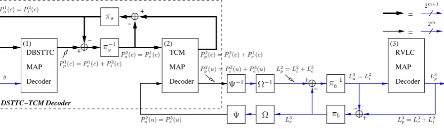
Figure 2: Block diagram of the iterative DBSTTC-TCM-RVLC decoder. The notationsπ(s,b)andπ−(s,b1)denote the interleaver and deinterleaver,
while the subscriptsorbdenotes the symbol-based or bit-based nature of the interleaver, respectively. Furthermore,ΨandΨ−1denote LLR-to-symbol and symbol-to-LLR probability conversion, whileΩandΩ−1
denote the addition and deletion of the LLRs of the side information and dummy bits of the RVLC.
tribution, a jointly optimised space time trellis coded modulation and source-coding scheme based on serially concatenated DBSTTC, TCM and RVLC is proposed. An efficient iterative turbo-detection scheme is utilised for exchanging information between the constituent codes for the sake of achieving full transmit diversity and a near-channel-capacity performance.
2. SYSTEM OVERVIEW
We employ the RVLCs designed in [11], where the codewords are
C={00,11,010,101,0110}associated with the source symbol se-quence ofu={0,1,2,3,4}. The associated source entropy is2.14
bits/symbol (BPS) and the average codeword length is2.46bits, giv-ing an RVLC codgiv-ing rate ofRRV LC = 2.14/2.46 = 0.87. The
RVLC outer encoder of Figure 1 maps the source symbol sequenceu
to a variable-length codeword sequenceb, which can be represented as a binary bit sequence at each encoding instance. A minimum num-ber of zero-valued dummy bits are concatenated to the RVLC’s output bit sequence, such that we have a constant-length TCM encoder’s in-put sequence. The side information related to the number of RVLC output bits per transmission frame conveying the RVLCs is explic-itly signalled to the decoder by repeating the side-information bits three times for the sake of invoking majority logic based detection and then the side information is further protected by the TCM scheme. More explicitly, the resultant bit sequence representing the RVLC out-put bits, dummy bits and side information bits is then treated as the input of the TCM encoder of Figure 1, which has a coding rate of
Rcm=mm+1and employs a2m+1-level modulation scheme [6].
The structure of the novel DBSTTC-TCM-RVLC turbo-detection
scheme is illustrated in Figure 2, where there are three constituent decoders, each labelled with a round-bracketed index. Two symbol-based and one bit-symbol-based MAP decoders [6] were employed, each op-erating in the logarithmic-domain, for the sake of decoding the DB-STTC, TCM and RVLC, respectively. The notationsP(c)andP(u)
denote the symbol probabilities of the (m+ 1) coded bits and them
uncoded information bits of the TCM scheme, respectively. The sub-scripts ofp,e,aandidenote thea posteriori,extrinsic,a priori
and intrinsicnature of the corresponding symbol probability, re-spectively. The notations Lp, Le and Li denote the
Logarithmic-Likelihood Ratio (LLR) of thea posteriori,extrinsicandintrinsic
information, respectively. The probabilities as well as the LLRs as-sociated with one of the three constituent decoders having a label of
1. . .3are differentiated by the superscript of1. . .3. Since the TCM scheme employs a systematic convolutional code, we haveP2
p(u) =
Pi2(u) +Pe3(u), wherePi2(u)denotes theintrinsicprobabilities of
the uncoded information symbols representing theextrinsic infor-mation provided by the decoder itself and the systematic inforinfor-mation obtained from the systematic part ofPe1(c). Similarly,Pi2(c)denotes
theintrinsicprobabilities of the TCM coded symbols representing theextrinsicinformation provided by the decoder itself and the sys-tematic part of the codewords obtained fromPe3(u). Hence, the
DB-STTC and RVLC decoders benefit from each other’s extrinsic infor-mation through the TCM decoder. At the final decoding iteration, the
a posterioriinformation of the RVLC’s coded bit, namelyL3 pof
Fig-ure 2, is fed to a sequence estimator for estimating the RVLC’s source symbol sequence denoted asuˆin Figure 1.
[image:2.595.88.538.219.350.2]TCM and DBSTTC codecs by parallel bit-based interleavers in Fig-ures 1 and 2. Note that the DBSTTC-BICM decoder is reminiscent of the Iteratively-Decoded BICM (BICM-ID) scheme [14], where a soft-decision based demodulator was employed by the BICM-ID scheme instead of the DBSTTC. A Set-Partitioning (SP) scheme [15] labelled as signal mapper was utilised by both the TCM and BICM-ID schemes. We also employed a SP labelled signal mapper for the BICM-RVLC scheme, since we found that the Gray-labelled RVLC was unable to outperform the SP-based DBSTTC-BICM-RVLC arrangement in our iterative decoding scheme.
3. CODE DESIGN FOR DBSTTC
0,2
0,3
. . .
. . .
0,3 L
. . .
. . .
0,1
0,0
R M=4, N=3
3,2
3,3
3,2
3,3 0,2
0,3
3,3 L 3,2 L L 1,0
0,2 0,1
0,3
3,2
3,3
Width
[image:3.595.356.529.69.399.2]Depth
Figure 3: The tree structure of all permutations for DBSTTC employ-ingN = 3transmit antennas and anM = 4-level modulator. The notationsRandLdenote the root node and leaf nodes, respectively.
A DBSTTC codeword consists ofNsymbols and theN-symbol codeword is transmitted usingNnumber of transmit antennas diago-nally allocated across the ‘space-time grid’ constituted by the anten-nas and the time-slots used. Therefore, the code design of a DBSTTC can be viewed as finding the best possible permutation for these code-words that give the largest minimum product distance,P Dmin[1].
As the transmit antennas are statistically equivalent to each other in the spatial domain, the permutation on the first antenna’s transmit-ted symbols, i.e. the first symbol of anN-symbol codeword, can be fixed in the natural order. Hence the permutation search is based on
N −1 symbols of theN-symbol codeword. It was shown in [1] that all the possible permutations for a DBSTTC can be represented by a tree. Figure 3 illustrates the corresponding tree structure of the DBSTTC scheme employingN = 3transmit antennas and an
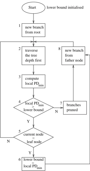
M = 4-level modulator, where each of the permutations ends in a leaf node in the tree. Hence the ‘branch-and-bound’ algorithm of [16] can be utilised for efficiently solving this permutation based optimisa-tion problem [1]. More specifically, this algorithm forms a tree struc-ture (branching operation), establishes a lower bound for theP Dmin
(bounding operation) and searches only the specific tree branches that have a local P Dminhigher than the lower bound. Figure 4
sum-marises the operation of this algorithm, where a permutation having aP Dminhigher than the lower bound is found, if the current node is
found to be a leaf node at block 5 of Figure 4. Then the lower bound is reinitialised as the newly foundP Dminand the process continues,
until there are no more branches emerging from the root node. In this contribution, we studied the effect of modulator choices
Start
min
local PD
min
local PD
min
local PD new branch from root
lower bound initialised
2 1
8 new branch
from father node traverse
the tree depth first
compute
Y
branches pruned
Y lower bound>
lower bound = 3
4
5
6
N 7
N leaf node
current node =
Figure 4: Flow chart of the branch-and-bound algorithm, where the minimum product distance is denoted asP Dmin.
0=000 1=001 2=010
6=110 3=011
5=101 7=111 4=100
6=110 7=111 5=101
0=000 2=010 4=100
[image:3.595.82.277.209.395.2]3=011 1=001
Figure 5: Phasor constellations of 8PSK (left) and 8APSK [8] (right).
on the achievableP Dminusing classic level PSK (8PSK), the
8-level Amplitude PSK (8APSK) scheme of [8] and a scheme we refer to as π/4-rotated 8-level Quadrature Amplitude Modulation (π/4 -8QAM). More explicitly, Figures 5 and 6 depict the phasor constel-lations of 8PSK, 8APSK andπ/4-8QAM. We found that when we haveθ = π/4and r1/r2 = 0.5177, the correspondingθ-rotated
θ-8QAM scheme of Figure 6 gives the bestP Dmin, since we have
ED(x1, x6) =ED(x1, x7) = ED(x6, x7), wherexidenotes the
[image:3.595.322.565.437.554.2]7=111 6=110
5=101 4=100
2=010 0=000
1=001
[image:4.595.320.564.69.243.2] [image:4.595.57.304.77.211.2] [image:4.595.96.268.254.300.2] [image:4.595.318.565.273.470.2]3=011 [0 4] [2 6] [1 5] [3 7] [0 2 4 6] [1 3 5 7]
[0 1 2 3 4 5 6 7]
b1=0 b1=1
b1=0 b1=1 b0=1 b0=0
r2
r1 θ
Figure 6: Theθ-8QAM modulator (left) havingr1/r2= 0.5177and
θ=π/4together with its set-partitioning construction (right).
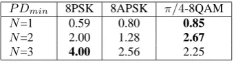
P Dmin 8PSK 8APSK π/4-8QAM
N=1 0.59 0.80 0.85
N=2 2.00 1.28 2.67
N=3 4.00 2.56 2.25
Table 1: The minimum product distance, P Dmin, of DBSTTC
schemes employingNtransmit antennas based on 8PSK, 8APSK and
π/4-8QAM.
8APSK andπ/4-8QAM. Note that when we haveN = 1,P Dmin
is simply given by the squared minimum Euclidean distance of the uncoded constellation. As we can see from Table 1,π/4-8QAM is optimum, when we haveN = 1(uncoded) andN = 2, whereas 8PSK is optimum forN = 3, in terms ofP Dmin. Hence, the best
achievableP Dmindepends on both the modulator type as well as on
the number of transmit antennas of the DBSTTC scheme.
In the next section, we will study the attainable performance of 8PSK-based DBSTTC havingN= 2andN= 3, as well as theπ/4 -8QAM-based DBSTTC arrangement havingN = 2in the context of the joint iteratively decoded system of Section 2 with the aid of a single receive antenna. The new codeset found forπ/4-8QAM-based DBSTTC havingN = 2is given by [0 1 2 3 4 5 6 7][4 5 6 7 3 0 1 2], while the codeset of 8PSK-based DBSTTC employingN= 2and
N= 3can be found from [1].
4. SIMULATION RESULTS
We will evaluate the achievable performance of both DBSTTC-TCM-RVLC and DBSTTC-BICM-DBSTTC-TCM-RVLC using the Bit Error Ratio (BER) versus signal to noise ratio per bit, namely Eb/N0. The BER is
calculated based on the hard decision value ofL3pseen in Figure 2
and on the sequencebof Figure 1. We employed the 64-state TCM scheme of [8] as well as a BICM scheme using Paaske’s 64-state non-systematic convolutional code described for example in [17, p. 331]. We refer to the iteration between the DBSTTC decoder and the TCM/ BICM decoder as an inner iterationIias well as the iteration between
the DBSTTC-TCM/BICM decoder and the RVLC decoder as an outer iterationIo. The total number of inner iterations invoked equals to
Iit=IoIi. The number of TCM/BICM coded symbols per
transmis-sion frame was fixed to 1024 8PSK orπ/4-8QAM symbols and the overall coding rate wasRa= 0.5733. The effective throughput was
η=Ralog2(8) = 1.72BPS.
Figure 7 shows the BER versusEb/N0performance of
DBSTTC-TCM/BICM-RVLC employingN = 2transmit antennas using both
8psk-dst21-cm-rvlc-star.gle
2 3 4 5 6 7 8 9
Eb/N0(dB)
10-6
10-5
10-4
10-3
10-2
10-1
100
B
E
R 8PSK/4-8QAM
Outer Iteration: Inner Iteration = 1 N = 2
8 4 2 1
DBSTTC-TCM-RVLC
DBSTTC-BICM-RVLC
Figure 7: BER versusEb/N0performance of the proposed
DBSTTC-TCM-RVLC and DBSTTC-BICM-RVLC schemes when communi-cating over fast Rayleigh fading channels. The effective throughput is 1.72 BPS. and the number of transmit antennas isN = 2.
8psk-dst31-bicmid-rvlc.gle
2 3 4 5 6 7 8 9
Eb/N0(dB)
10-6
10-5
10-4
10-3
10-2
10-1
100
B
E
R
DBSTTC-BICM-RVLC N=3
Outer Iteration: Inner Iteration = 1
8 6 4 2 1
Figure 8: BER versusEb/N0 performance of the proposed
8PSK-based DBSTTC-BICM-RVLC scheme when communicating over fast Rayleigh fading channels. The effective throughput is 1.72 BPS. and the number of transmit antennas isN = 3.
8PSK andπ/4-8QAM. We can see from Figure 7 that as predicted, DBSTTC-TCM-RVLC outperformed DBSTTC-BICM-RVLC. How-ever, the advantage of π/4-8QAM over 8PSK becomes significant only for DBSTTC-BICM-RVLC, but not for DBSTTC-TCM-RVLC. Figures 8 and 9 illustrate the BER versus Eb/N0 performance of
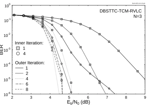
DBSTTC-TCM/BICM-RVLC employingN = 3transmit antennas using 8PSK. It is clear from Figures 7 to 9 that DBSTTC-TCM/BICM-RVLC benefits from having both a transmit diversity gain and a sig-nificant iteration gain, when the number of transmit antennas is in-creased. Again, DBSTTC-TCM-RVLC outperformed DBSTTC-BICM-RVLC atN= 3.
As illustrated in Figure 9, a significant iteration gain was achieved, when the number of outer iterations was increased. Explicitly, at
Ii = 1andIo = 1there is no feedback from the TCM scheme to
the DBSTTC arrangement or from the RVLC to the TCM decoder. When Iiwas increased from 1 to 4 and we had Io = 1, iterative
8psk-dst31-tcm-rvlc.gle
2 3 4 5 6 7 8 9
Eb/N0(dB)
10-6
10-5
10-4
10-3
10-2
10-1
100
B
E
R
DBSTTC-TCM-RVLC N=3
Inner Iteration:
4 1
Outer Iteration:
[image:5.595.58.302.69.243.2]8 6 4 2 1
Figure 9: BER versusEb/N0 performance of the proposed
8PSK-based DBSTTC-TCM-RVLC scheme when communicating over fast Rayleigh fading channels. The effective throughput is 1.72 BPS. and the number of transmit antennas isN= 3.
to the TCM decoder yet. It is shown in Figure 9 that at BER=10−4an
SNR gain of approximately 2.5 dB was attained by the scheme having
It
i =Ii= 4andIo= 1compared to the non-iterative scheme having
Iit=Ii=Io= 1. This shows that the iterative decoding exchanging
information between the DBSTTC and TCM schemes was very effi-cient. Let us now consider the scheme havingIi = 1andIo = 4,
resulting in a total ofIit = 4 iterations between the DBSTTC and
TCM schemes as well asIo = 4iterations between the RVLC and
the DBSTTC-TCM decoder. By comparing the BER performance of the scheme havingIi= 1andIo= 4(Iit = 4) to that of the scheme
having Ii = 4and Io = 1 (Iit = 4) at BER=10−4 in Figure 9,
we observe that a further 0.8 dB SNR gain was achieved, when the the number of iterationsIo was increased from 1 to 4, while having
It
i = 4. Therefore, the iterative decoder exchanging information
be-tween the RVLC and DBSTTC-TCM decoders is capable of further enhancing the system’s achievable performance.
As we observe from Figures 7 and 9, the best DBSTTC-TCM-RVLC scheme using 8PSK requiresEb/N0= 4.67dB andEb/N0=
4.22dB when we haveN= 2andN= 3, respectively, for attaining a BER of10−4
. Note that for an effective throughput of1.72BPS, the Rayleigh fading channel capacity of an 8PSK-based spacetime code employingN= 2andN= 3transmit antennas isEb/N0 = 2.95dB
andEb/N0 = 2.60dB, respectively, according to the calculations
provided in [18]. Hence the proposed DBSTTC-TCM-RVLC sys-tem employing two and three transmit antennas is capable of op-erating within about 1.72 dB and 1.62 dB from the corresponding channel capacity, respectively, when aiming for a throughput of
1.72BPS using 8PSK.
5. CONCLUSIONS
In this contribution the novel concept of amalgamated DBSTTC, TCM/ BICM and RVLC aided transmission was proposed. The achievable performance benefits were demonstrated in the context of the novel iterative turbo-decoding mechanism exchanging information between the constituent decoders, when communicating over uncorrelated Ray-leigh fading channels. Specifically, the proposed DBSTTC-TCM-RVLC employing two and three transmit antennas was capable of performing within 1.72 dB and 1.62 dB, respectively, from the
cor-responding channel capacity. It was also shown in Section 3 that the optimum DBSTTC design depends on both the modulator type as well as on the number of transmit antennas employed.
6. REFERENCES
[1] M. Tao and R. S. Cheng, “Diagonal Block Space-time Code Design for Diversity and Coding Advantage over Flat Rayleigh Fading Channels,” IEEE Transactions on Signal Processing, pp. 1012–1020, April 2004.
[2] N. Seshadri and J. H. Winters, “Two signaling schemes for improving the error performance of frequency-division-duplex (FDD) transmission systems using transmit antenna diversity,” Int. J. Wireless Information Network, vol. 1, no. 1, pp. 49–60, 1994.
[3] A. Wittneben, “A New Bandwidth Efficient Transmit Antenna Modu-lation Diversity Scheme for Linear Digital ModuModu-lation,” International Conference on Communications (ICC), vol. 3, pp. 1630–1634, May 1993.
[4] S. Li, X. Tao, W. Wang, P. Zhang and C. Han, “Generalized Delay Diversity Code: A Simple and Powerful Space-time Coding Scheme,” IEEE International Conference on Communication Technology (ICCT) , pp. 1697–1703, August 2000.
[5] V. Tarokh, N. Seshadri and A. R. Calderbank, “Space-time Codes for High Rate Wireless Communication: Performance analysis and code construction,” IEEE Transactions on Information Theory, vol. 44, pp. 744–765, March 1998.
[6] L. Hanzo, T. H. Liew and B. L. Yeap, Turbo Coding, Turbo Equalisation and Space Time Coding for Transmission over Wireless channels. New York, USA: John Wiley IEEE Press, 2002.
[7] S. M. Alamouti, “A Simple Transmitter Diversity Scheme for Wireless Communications,” IEEE Journal on Selected Areas in Communications, vol. 16, pp. 1451–1458, October 1998.
[8] G. Ungerb¨ock, “Channel Coding with Multilevel/Phase Signals,” IEEE Transactions on Information Theory, vol. 28, pp. 55–67, January 1982.
[9] E. Zehavi, “8-PSK trellis codes for a Rayleigh fading channel,” IEEE Transactions on Communications, vol. 40, pp. 873–883, May 1992.
[10] L. Hanzo, P.J. Cherriman and J. Street, Wireless Video Communications: Second to Third Generation Systems and Beyond. NJ, USA : IEEE Press., 2001.
[11] Y. Takishima, M. Wada and H. Murakami, “Reversible Variable Length Codes,” IEEE Transactions on Communications, vol. COM-43, no. 2/3/4, pp. 158–162, 1995.
[12] R. Bauer, J. Hagenauer, “On Variable Length Codes for Iterative Source/Channel Decoding,” in IEEE Data Compression Conference, (UT, USA), pp. 273–282, 27-29 March 2001.
[13] S. X. Ng, F. Guo, J. Wang, L-L. Yang and L. Hanzo, “Joint Source-coding, Channel-coding and Modulation schemes for AWGN and Ray-leigh Fading Channels,” IEE Electronics Letters, vol. 39, pp. 1259–1261, August 2003.
[14] X. Li, J. A. Ritcey, “Bit-interleaved coded modulation with iterative de-coding using soft feedback,” IEE Electronics Letters, vol. 34, pp. 942– 943, May 1998.
[15] D. Divsalar and M. K. Simon, “The design of trellis coded MPSK for fading channel: Set partitioning for optimum code design,” IEEE Trans-actions on Communications, vol. 36, pp. 1013–1021, September 1988.
[16] G. L. Nemhauser, A. H. G. Rinnooy Kan and M. J. Todd, Optimization. Amsterdam, The Netherlands: North-Holland, 1989.
[17] S. Lin and D. J. Costello, Jr, Error Control Coding: Fundamentals and Applications. Inc. Englewood Cliffs, New Jersey 07632: Prentice-Hall, 1983.