Upgrade to the Birmingham Irradiation Facility
P. Dervan
a, R. French
b, P. Hodgson
b, H. Marin-Reyes
b, K. Parker
b,n, J. Wilson
c, M. Baca
c aThe University of Liverpool, Department of Physics, United Kingdom b
The University of Sheffield, Department of Physics and Astronomy, United Kingdom cThe University of Birmingham, School of Physics and Astronomy, United Kingdom
a r t i c l e i n f o
Available online 11 February 2015
Keywords: Cyclotron Irradiation Silicon sensors Scanning system Robot Cooling
a b s t r a c t
The Birmingham Irradiation Facility was developed in 2013 at the University of Birmingham using the Medical Physics MC40 cyclotron. It can achieve High Luminosity LHC (HL-LHC)fluences of 1015(1 MeV neutron equivalent (neq)) cm 2in 80 s with proton beam currents of 1
μ
A and so can evaluate effectively the performance and durability of detector technologies and new components to be used for the HL-LHC. Irradiations of silicon sensors and passive materials can be carried out in a temperature controlled cold box which moves continuously through the homogenous beamspot. This movement is provided by a pre-configuredXY-axis Cartesian robot scanning system. In 2014 the cooling system and cold box were upgraded from a recirculating glycol chiller system to a liquid nitrogen evaporative system. The new cooling system achieves a stable temperature of 501C in 30 min and aims to maintain sub-01C temperatures on the sensors during irradiations. This paper reviews the design, development, commissioning and performance of the new cooling system.&2015 The Authors. Published by Elsevier B.V. This is an open access article under the CC BY license (http://creativecommons.org/licenses/by/4.0/).
1. Introduction
In approximately 2024, the Large Hadron Collider (LHC) will be upgraded to the HL-LHC. The upgrade is foreseen to increase the LHC design luminosity by a factor of 10. This planned increase in luminosity results in significantly higher levels of radiation inside the planned ATLAS Upgrade detector [1]. This means existing detector technologies together with new components and materi-als need to be re-examined to evaluate their performance and durability within this enhanced radiation field. Of particular interest is the effect of radiation on the upgraded ATLAS tracker. To study these effects an ATLAS irradiation scanning facility using the Medical Physics Cyclotron at the University of Birmingham was built in 2013[2]. A 1
μ
A beam of 27 MeV protons allows irradiated samples to receive in 80 s,fluences corresponding to 10 years of operation at the HL-LHC, 1015 (1 MeV neutron equivalent (neq)) cm 2. Since commissioning in early 2013 this facility has been used to irradiate silicon sensors, optical components and carbon fibre sandwiches for the ATLAS upgrade programme[2]and up to September 2014, 211 samples have been irradiated. Irradiations of silicon sensors and passive materials are carried out in a tempera-ture controlled cold box which moves continuously through the homogenous 1 1 cm2beamspot. This movement is provided by the scanning system, Fig. 1, which can move at speeds from
1 mm s 1 to 10 mm s 1 in the horizontal direction and up to 25 mm s 1 in the vertical direction [2]. In 2014, upgrades have been made to the cooling system, moving from a recirculating glycol chiller system to a liquid nitrogen (LN2) evaporative system, as well as upgrades to the cold box to increase the window size to allow irradiations of larger samples. These upgrades were moti-vated by the limitations of the glycol system which resulted in overheating of sensors during irradiations, causing annealing, as discussed inSection 3. The new system was developed with the specification to maintain sub-01C within the samples during irradiations. Initial tests of the LN2 system were performed [3] and results showed that temperatures of 501C could be achieved, an ideal base temperature for irradiating silicon sensors. These upgrades have been installed and commissioned in the Birmingham Irradiation Facility.
2. The scanning system and initial cold box
The scanning system is controlled using a NI RIO Real-Time programmable controller with a LabView GUI [4]. This also monitors the temperature and humidity within the cold box. However the temperature of the sensors during irradiations could not be measured directly due to the adverse effect of the beam on the PT1000 sensors. Instead the temperature of a sensor, in a test setup simulating beam conditions, was measured and also other in-beam checks of temperature were made. These are described Contents lists available atScienceDirect
journal homepage:www.elsevier.com/locate/nima
Nuclear Instruments and Methods in
Physics Research A
http://dx.doi.org/10.1016/j.nima.2015.02.005
0168-9002/&2015 The Authors. Published by Elsevier B.V. This is an open access article under the CC BY license (http://creativecommons.org/licenses/by/4.0/). nCorresponding author.
in Section 5. The initial cold box was based on the CERN-PS irradiation setup [5] using recirculating glycol and the box is purged with dry N2 to prevent condensation forming. The cold box reaches 151C with approximately a 2 h cooling time. Fans within the box are also used to ensure good air circulation. The scan time depends on the size of the sample, the requiredfluence and the beam current. For reference, a 1 cm2 sample can be irradiated to 1015n
eqcm 2 in 80 s using a 1
μ
A beam, and the scan time scales linearly with current. Two types of carbonfibre frames, seeFig. 2, are used for sensor irradiations:1. Pixel frame: 3 slots, 2 for double pixel sensors (4.2 1.9 cm2) and 1 for single pixel sensors (2.2 1.9 cm2).
2. Mini frame: 3 3 slots for 1 1 cm2sensors.
Kapton tape is used to attach samples to the frame which then clips into a mount on the underside of the cold box lid. The sample position is measured relative to a reference point,‘Home position’ to ensure the precise location of the samples, which is essential to calculate the scan path and ensure uniform irradiation. The scan path requires several input parameters from the user: the offsetx (horizontal) andy(vertical) positions of the sample with respect to ‘Home’, the area to be scanned, the speed of the scan in the x-axis, and the beam current which is used to calculate the number of scans to achieve the requiredfluence. Each run starts and ends with the‘Home’position and scans horizontally over the area with 0.5 cm vertical displacement between horizontal scans, seeFig. 3.
3. Irradiated samples
I–Vand charge collection measurements were performed on a mini sensor irradiated at Birmingham to 1015n
eqcm 2 at 1
μ
A which indicated that the sensor had overheated[3]. In order to cross-check these results, the charge collection measurements were compared to results from other facilities. The same type of sensors were used for the comparison so that the behaviour of the sensors irradiated to the samefluence, should be equivalent. The results from Birmingham are compared to charge collection measurements from two other facilities: KEK and Los Alamos. KEK uses a 70 MeV proton beam with currents up to 1μ
A[7]. Los Alamos uses a pulsed 200 MeV proton beam with beam current of 80 nA (unshielded) or up to 1μ
A shielded [8]. While the other facilities can also irradiate to high fluences, the Birmingham facility is able to attain a targetfluence in a shorter time (for the same beam current) due to a larger damage factor caused by 27 MeV protons[9]. [image:2.595.50.289.58.370.2]InFig. 4, the charge collection measurements are shown. KEK and Los Alamos measure a similar charge collection on the sensor, whilst Birmingham collects more charge, indicating that the sensor has received less radiation damage. To investigate further, the KEK and Los Alamos sensors were deliberately annealed by heating to 801C for 60 min. Charge collection measurements of the annealed sensors were made and compared to the Birming-ham sensor, which had not been heated. The similarity of the charge collected in all three sensors in Fig. 5 suggests that the Birmingham sensor had also been annealed and it is likely that this occurred during the irradiation, due to overheating. Fig. 1. The scanning system and cold box in the Birmingham Irradiation Facility.
[image:2.595.316.557.58.217.2]Fig. 2. Carbonfibre pixel frame with gafchromicfilm[6]after exposure to beam.
[image:2.595.48.289.415.561.2]The overheating takes the form of brief but large temperature increases during the period that the sensor is moving through the beam spot. This is due to the 27 MeV protons depositing energy in the sensors at a rate of 1.1 W, causing significant temperature increases. Similarly, I–V measurements were made which also show evidence of annealing of the Birmingham sensors. The current of the irradiated Birmingham sensors is significantly larger than the KEK and Los Alamos sensors both before and after annealing.
4. Upgrades
In order to prevent overheating in subsequent irradiations, the maximum beam current was reduced to 0.5
μ
A. Whilst a tempor-ary solution, this limits the potential to irradiate to highfluences as the scan time is doubled compared to using a beam current of 1μ
A. As a more practical solution, improvements were made to the cooling system in order to optimise the air circulation within the cold box.Cooling system. A Norhof[10]liquid nitrogen (LN2) system using evaporative cooling was installed, as shown in the bottom left ofFig. 6. The LN2is dripped on to a heat sink located at the base of the cold box. The LN2evaporates to produce very cold N2gas. The flow of LN2 in to the cold box is adjusted automatically by the Norhof system, which operates by monitoring the temperature and pumping in LN2to achieve the preset required temperature of Fig. 4.Charge collection measurement comparing sensors irradiated to 1015
neqcm 2
at Birmingham, Los Alamos and KEK. Note: the unusual behaviour of the Birmingham sensor compared to the other facilities.
[image:3.595.309.548.56.380.2]Fig. 5.Charge collection measurement comparing sensors irradiated to 1015neqcm 2at Birmingham, Los Alamos and KEK, after Los Alamos and KEK sensors had been annealed by heating to 801C for 60 min where the behaviour of the sensors is similar among all facilities.
[image:3.595.37.282.58.207.2]Fig. 6.The upgraded system installed in the Birmingham Irradiation Facility with the LN2system and dewar to the left of the scanning system with the new cold box and the Faraday cup with a green stand. (For interpretation of the references to colour in thisfigure caption, the reader is referred to the web version of this paper.)
Fig. 7.Carbonfibre frame for mini sensors (1 cm2
[image:3.595.38.280.252.403.2] [image:3.595.308.548.469.706.2]the cold box. The new cooling system can achieve a stable temperature of 501C in 30 minutes.
Cold box. A new box has been made with a larger volume and window size. Further to this, a more powerful fan has been installed to circulate the cold nitrogen gas. The box is purged with dry nitrogen before and after running.
Carbonfibre frames. Square recesses, in to which 1 cm2 mini-sensors can fit, have been added to the frames to reduce the amount of kapton tape needed to secure the samples (Fig. 7). This allows more exposure to the cold nitrogen in order to maintain sub-01C temperatures on the sensors. The frames can also be redesigned to eliminate kapton tape by using a frame which secures the sensor between two thin sheets of carbonfibre, with maximum air exposure on both faces of the sensor.
Further improvements. To reduce the amount of time that the samples are exposed to the beam, a further possibility is to increase the horizontal speed of the scanning table from 1 mm s 1 up to a possible 10 mm s 1. The scan time does not change and the samples will experience more heating cycles but will not be heated for long enough to reach high temperatures which pre-vents annealing. With a greater scanning speed, large spikes in the temperature of the sensor can be avoided as well as reduce the maximum temperature on the sensors.
5. Temperature measurements
Temperature is measured by PT1000 sensors (1 k
Ω
platinum resistance temperature detectors). As discussed inSection 2, the temperature of the sensor could not be measured during the irradiation due to the heating effect of the beam on the PT1000 sensor. Therefore, in order to check whether temperatures, high enough to produce the annealing described inSection 3could be produced, a test setup was developed to simulate the effect of a 1μ
A beam[3]. For example, a 1μ
A 27 MeV proton beam deposits energy in our silicon sensor at a rate of 1.1 W, which causes large temperature increases. With the LN2cold box base temperature of 501C, the initial temperature tests indicate that the sensor temperature plateaus at 51C, which suggests that irradiations can be performed at 1μ
A, at 1 mm s 1horizontal speed with the new cooling system. However, due to poor thermal contactbetween the mini heater and sensor and the fragility of the PT1000s when glued to silicon sensors, further tests were performed.
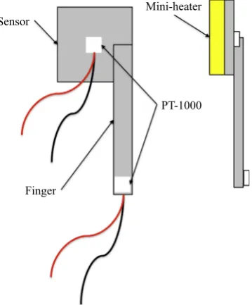
Temperature cannot be measured directly by placing a PT1000 on the sensor because the PT1000 heats up very significantly when irradiated by the beam. Therefore a reliable method of temperature measurement, using a thin finger of silicon of identical type to the sensor, has been developed. The finger is glued to the sensor where it overlaps by 0.5 cm, see Fig. 8, and PT1000s are glued to the centre of the sensor and the end of the finger. Current studies aim to determine the maximum tempera-ture of the silicon during irradiations by calculating an offset between thefinger temperature and the true temperature of the sensor. Thermodynamic modelling is used to calculate the heat transfer in the system and compare experimental results. Using a fixed beam current of 1
μ
A, several horizontal scanning speeds were tested to determine whether by minimising the time on each sensor, the maximum temperature within the sensor decreases to a reasonable value. The speeds tested were, 1 mm s 1(the default value), 2 mm s 1, 4 mm s 1 and 8 mm s 1. The sensors were placed in the top right position, as inFig. 3, and the beam scans over the sensor three times. This corresponds to three, well separated temperature peaks at low speeds as the 1 cm2 sensor is exposed to the beam for 10 s per scan at 1 mm s 1. This also means that the time between beam exposure per scan is larger than at faster speeds so allows the sensor to cool, resulting in three sharp peaks. At higher speeds, such as 4 mm s 1, the peaks become broader for each scan, and the first and second peaks are less resolved as demonstrated inFig. 9. This is due to the short time between the scans, with peak one as a shoulder of peak two at 601 s. At higher speeds, lower temperatures are measured on the sensor, as expected, due to shorter time per scan through the beam however they do not have time to cool down.Fig. 9shows the measured temperature of the finger at 1μ
A and these temperatures can be used to compare to the finger temperature as predicted by the thermodynamic model. An offset between the measured finger temperature and the true temperature on the sensors will be calculated using the model. This will determine the maximum temperature on sensors during irradiations and provide final conclusions on the optimum operating speeds.6. Summary
Upgrades to the Birmingham Irradiation Facility have been made with respect to the setup in [2,3]. A new cooling system has been tested and installed, using a liquid nitrogen evaporative
Mini-heater
PT-1000
[image:4.595.316.558.57.210.2]Finger Sensor
Fig. 8.Siliconfinger glued to sensor with PT1000s attached in the centre of the sensor and the end of thefinger. Left: Front view withfinger overlapping by 0.5 cm on 11 cm2
[image:4.595.80.260.497.714.2]sensor. Right: Side view with mini-heater.
Fig. 9. Temperature of siliconfinger against time for a 4 mm s 1
cooling system. This significantly reduces the baseline tempera-ture of the cold box from 151C with the glycol system, to 501C with a setup time of 30 min. New carbonfibre frames with square recesses for slotting in sensors and limiting the use of kapton tape have been made with planned improvements to eliminate kapton tape completely to ensure that the sensors are not insulated by the tape. Finally, the cold box has been remade with an increased window size of 150 150 mm2 to enable larger samples to be irradiated. The improvements to the system have been shown to maintain a sub-01C temperature on the sensors whilst irradiating. Further tests are ongoing to increase the horizontal speed from 1 mm s 1to reduce the time the beam is incident on the sensors and hence to reduce the temperature increase as the sample scans through the beam.
Acknowledgements
We are very grateful to Prof. D. Parker, Director of the Medical Physics Cyclotron, and his team, especially Mr. M. Smith, for setting up the proton beam and for their help in installing our apparatus. We also thank our technical colleagues in our home universities for their invaluable support.
References
[1] ATLAS Collaboration, Letter of Intent for the Phase-II Upgrade of the ATLAS Experiment, CERN-LHCC-2012-022. LHCC-I-023. 2012.
[2] P. Dervan, R. French, P. Hodgson, H. Marin-Reyes, J. Wilson, Nuclear Instru-ments and Methods in Physics Research Section A 730 (2013) 101.http://dx. doi.org/10.1016/j.nima.2013.05.156.
[3] P. Dervan, R. French, P. Hodgson, H. Mari-Reyes, K. Parker, J. Wilson, M. Baca, Scanning facility to irradiate mechanical structures for the LHC upgrade programme, in: Proceedings of TIPP2014 Conference(PoS(TIPP2014)419), Amsterdam, The Netherlands, 2014.http://pos.sissa.it/cgi-bin/reader/contribu tion.cgi?id=PoS(TIPP2014)419.
[4] H. Marin-Reyes, R. French, P. Hodgson, K. Parker, J. Wilson, P. Dervan, Pre-configuredxy-axis Cartesian robot system for a new ATLAS scanning facility, in: Mobile Service Robotics: Proceedings of CLAWAR 2014, Poznan, Poland, 21–23 July 2014, World Scientific Publishing Co., 2014, pp. 477–483,http://dx. doi.org/10.1142/9789814623353_0056.
[5] M. Glaser, et al., Nuclear Instruments and Methods in Physics Research Section A 426 (1999) 72.http://dx.doi.org/10.1016/S0168-9002(98)01472-7. [6] Ashland, Gafchromic Radiotherapy Films, URL〈http://www.ashland.com/pro
ducts/gafchromic-radiotherapy-films〉.
[7] CYRIC, AVF Cyclotron, URL〈http://www.cyric.tohoku.ac.jp/english/facilities/ guide/cyclotron.html〉.
[8] Los Alamos National Laboratory, LANSCE User Guide, URL〈http://lansce.lanl. gov/media/WNRUserGuide.pdf〉.
[9] E. Fretwurst, G. Lindstrom, I. Pintilie, J. Stahl, Radiation Damage in Silicon Detectors Caused by Hadronic and Electromagnetic Irradiation, ArXiv Physics e-printsarXiv:physics/0211118.