JET
JOINT
UNDERTAKING
PROGRESS
REPORT 1985
REFERENCE
ONLY
DAT E 2 6 LUG. 1989
EUR 10616 EN (EUR-JET-PR3) March 1986.
Editorial work on this report was carried out by B.E. Keen The preparation for publication was undertaken by
the Documentation Service Units, Culham Laboratory.
© Copyright ECSC/EEC/EURATOM, Luxembourg 1986 Enquiries about copyright and reproduction should be addressed to:
The Publications Officer, JET Joint Undertaking, Abingdon, Oxon. 0X14 3EA, England
Contents
Introduction, Background and Report Summary 3
Technical Achievements During 1985 12
— Torus Systems; 12 — Power Supply and Magnet Systems; 13
— Neutral Beam Heating System; 15
— R.F. Heating System; 19
— CODAS; 20 — Diagnostic Systems; 24
— Remote Handling; 28 — Tritium Handling. 31
Scientific Achievements During 1985 34
— Plasma Optimization; 34 — Plasma Position and Current Control (PPCC); 35
— Impurities and Radiation Losses; 36 — Plasma Boundary Phenomena; 39 — Instabilities and Disruptive Phenomena; 43
— R.F. Heating; 45 — Energy Confinement; 47
— Theory; 48 — Summary of JET Results. 49
Developments and Future Plans 51
— Separatrix Experiments; 51 — Control of Sawteeth Oscillations; 52
— Profile Control; 54 — Multi-Pellet Injection for Fuelling/Re-Fuelling; 55
— Density Control and Separatrix Dump Plates. 56
Appendices 58
I Work of Theory Division 58
II Task Agreements — Present Status 69 III List of Articles, Reports and Conference Papers Published, 1985 71
IV Reprints of JET Papers: 83 (a) JET-R(85)03 Low Ζ Material for Limiters and Wall Surfaces in JET: Beryllium and Carbon; 83
(b) JET-P(85)08 Impurity and Radiation Studies during the JET Ohmic Heating Phase; 101 (c) JET-P(85)10 JET Contributions to 12th European Conference on Controlled Fusion and Plasma
Physics, Budapest, Hungary 2-6 September 1985; 121
(d) JET-P(85)15 Latest Results from JET; 235 (e) JET-P(85)18 Magnetic Topology, Disruptions and Electron Heat Transport; 251
(f) JET-P(85)20 ICRF Studies on JET; 265 (g) JET-P(85)25 Sawtooth Oscillations; 281 (h) JET-P(85)26 JET Contributions to the 11th Symposium on Fusion Engineering (Austin, Texas,
This is the third JET Progress Report which covers the second full year of JET's operation. These Progress Reports were introduced in 1983 to provide a more detailed account of JET's scientific and technical progress than that contained in the JET Annual Reports. The first two Reports (in 1983 and 1984) described the main activities and advances made on JET during the relevant periods, and concentrated on the scientific and technical involvement of the relevant JET Departments.
These previous Progress Reports provided good reference documents of JET developments and results during the early operation period, before these advances were published in the conventional literature. Now, JET results receive world-wide dissemination at international Conferences and meetings and in various scientific journals, at an earlier stage. Therefore, there is now less need for such a detailed record of all JET events, as the machine now operates almost in a routine manner. In addition, the staff effort required for preparation and compilation of the text was considerable and in many cases produced a duplication of material already published. Consequently, it was decided to change the format of the 1985 Progress Report, so that it provided an overview summary of the scientific and technical advances during the year, supplemented by appendices of detailed contributions (in preprint form) of the more important JET articles produced during that year. This Report represents an experiment in this respect, and comments from recipients would be welcomed.
The document is still aimed not only at specialists and experts engaged in nuclear fusion and plasma physics, but also at a more general scientific community. To assist in meeting these general aims, the Report contains a brief summary of the background to the Project, describes the basic objectives of JET and the principal design aspects of the machine. In addition, since the Project Team structure was changed during 1985, these changes are detailed, as it is within this structure that the activities and responsibilities for machine operation are carried out and the scientific programme is executed.
1985 was marred by the sudden and untimely death, on 30 June, of Dr Hans-Otto Wüster, the then Director of the Project. We shall always be indebted to him for his leadership and contributions to the formation and success of the Project. Many tributes to his memory came from all over the world. Fusion in Europe and the world has lost a great man, but, above all, everyone within the JET Project has lost a great friend.
As the new Director, it will be a difficult task to follow such a leader as Dr Wüster, but with the dedication, enthusiasm and skill of all Project staff, I am sure that this obstacle will be surmounted and we will continue to meet with confidence the tremendous challenges offered by the Project. Other changes in the Project included that of Dr R J Bickerton, formerly an Associate Director and Head of Scientific Department, who was appointed Deputy Director and Head of Heating and Theory Department. Also Dr M Keilhacker joined JET from IPP Garching, F.R.G., as an Associate Director and Head of the Experimental Department.
During 1985, the machine again provided excellent technical performance. The Project entered Phase IIA of its programme devoted to additional heating studies to observe the effects of large power ion cyclotron resonance heating (ICRH) on the plasma temperature and confinement properties. Two RF antenna had been installed during the shutdown at the end of 1984, and these were used during operations in the first half of 1985. From July, a four month shutdown was scheduled to allow installation of additional components including a third RF antenna. Final preparations were also completed for the first neutral injection system. Operations were continued until the end of the year. In 1985, there was 1446 tokamak pulses with plasma current exceeding 1 MA. This represented a consistent increase over 69 in 1983 and 472 in 1984. Throughout 1985, many plasma pulses were produced with the maximum rated toroidal magnetic field value of 3.45T. A plasma current of 5 MA was reached and maintained for 1 s. At present, machine operations at high currents are restricted to plasma elongation ratios of 1,4 to avoid the possibility of damage to the machine, if control of the vertical stability was lost. The design of new vessel supports is nearly complete and when installed, this restriction should be removed. Other modifications are planned to enable the current to be maintained at 5 MA for longer time periods, with the possibility of cautiously raising the current to higher levels.
the beneficial effects of this mode have still to be demonstrated on JET.
Plasma impurities remained high in 1985, as previously, and although they do not lead to a significant radiated power loss from the plasma core, they dilute the number of ions available for useful fusion reactions. A combination of multiple pellet refuelling and powerful additional heating, which will be tested in 1987, are likely contenders to improve this situation.
The scientific results so far achieved on JET are encouraging. In terms of the plasma parameters — density, temperature and confinement — JET has already reached the stage where each of these parameters is within a factor of two of three of those needed for fusion reactor. At the end of 1985, the first
neutral injection system for additional heating was installed and this will further improve the additional heating power introduced into the plasma.
The successful construction of the device and the most encouraging results obtained so far are a tribute to the dedication and skill of all who work on the Project. They also reflect the continuous co-operation and assistance received from the Associated Laboratories and from the Commission of the European Communities. They support the confidence and guidance given to the Project management by the JET Council, JET Executive Committee and JET Scientific Council.
With such devotion from all sides, the Project faces, with confidence, the many problems and challenges that are likely to be encountered in the future.
Report Summary
Introduction
Following the formal start of the Operation Phase of the JET Project in June 1983, it was decided to produce an annual JET Progress Report which should provide a more detailed account of JET's scientific activities than that which was provided in the JET Annual Report. The first two JET Progress Reports (EUR-JET-PR1) and (EUR-JET-PR2) described activities and advances up to the end of 1983 and 1984, respectively, and concentrated mainly on the scientific and technical activities of the relevant Departments in JET.
Although it was desirable to have this detailed record of JET's achievements and advances in all its aspects, the staff effort involved in preparation and compilation of the text was considerable and the information was already outdated by the time of publication. Consequently, for the 1985 version, it was decided that, in order to speed up the production process and to minimise the staff effort involved, a Progress Report would be produced which provided an overall summary of the scientific and technical advances achieved during the year, followed by appendices of detailed contributions (in preprint form) of the most important JET technical articles produced during that year. As an experiment, this is the first Progress Report produced in this form.
For completeness, this section contains a brief summary of the background to the Project. It describes the basic objectives of JET and the principal design aspects of the machine. In addition, since the Project Team structure was changed during 1985, these changes are detailed, as it is within this structure that the activities and responsibilities for machine operation are carried out and the scientific programme is executed.
Background
Objectives of JET
The Joint European Torus (JET) is the largest single project of the nuclear fusion research programme of the European Atomic Energy Community (EURATOM). The project was designed with the essential objective of obtaining and studying plasma in conditions and with dimensions approaching those needed in a fusion reactor.
The studies are aimed at:
a) Investigating plasma processes and scaling laws, as plasma dimensions and parameters approach those necessary for a fusion reactor;
b) Examining and controlling plasma-wall interactions and impurity influxes in near-reactor conditions;
c) Demonstrating effective heating techniques, capable of approaching reactor temperatures in JET, in the presence of the prevailing loss processes (particularly, RF and Neutral Beam Heating processes);
d) Studying alpha-particle production, confinement and subsequent plasma interaction and heating produced as a result of fusion between deuterium and tritium.
Two of the key technological issues in the subsequent development of a fusion reactor are likely to be faced for the first time in JET. These are the use of tritium and the application of remote maintenance and repair techniques. The physics basis of the post-JET programme will be greatly strengthened if other fusion experiments currently in progress are successful. The way should then be clear to concentrate on the engineering and technical problems involved in progressing from an advanced experimental device like JET to a prototype power reactor.
Basic JET Design
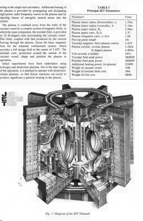
acting as the single turn secondary. Additional heating of the plasma is provided by propagating and dissipating high power radio frequency waves in the plasma and by injecting beams of energetic neutral atoms into the system.
The plasma is confined away from the walls of the vacuum vessel by a complex system of magnetic fields, in which the main component, the toroidal field, is provided by 32 D-shaped coils surrounding the vacuum vessel. This field, coupled with that produced by the current flowing through the plasma, forms the basic magnetic field for the tokamak confinement system, which provides a full design field at the centre of 3.45T. The poloidal coils, positioned around the outside of the vacuum vessel, shape and position the plasma in operation.
[image:10.595.61.548.48.802.2]Initial experiments have been undertaken using hydrogen and deuterium plasmas, but in the later stages of the operation, it is planned to operate with deuterium-tritium plasmas, so that fusion reactions can occur to produce significant α-particle heating in the plasma.
TABLE I
Principal JET Parameters
Parameter
Plasma minor radius (horizontally), a Plasma minor radius (vertically), b Plasma major radius, R0
Plasma aspect ratio, P^/a Plasma elongation ratio, e=b/a Flat top pulse length
Toroidal magnetic field (plasma centre) Plasma current, circular plasma
D shaped plasma Volt-seconds available
Toroidal field peak power Poloidal field peak power
Additional heating power (in plasma) Weight of vacuum vessel
Weight of toroidal field coils Weight of iron core
Value
1.25m 2.10m 2.96m 2.37
1.68 10s 3.45T 3.2MA 4.8MA 34Vs 380MW 300MW 25MW
108t 384t 2800t
J
B H D
TL1I
In order to reach conditions close to those relevant to a fusion reactor, a plasma density of — 1020m3 at a temperature of lOkeV would be needed. Even with a current of 4.8MA in JET, this would be inadequate to provide the temperature required using ohmic heating alone. Consequently, additional heating is required and two main systems are gradually being added to JET over the years, as follows:
• Injection into the plasma of highly energetic neutral atoms (Neutral Injection Heating) • Coupling of high power electromagnetic
radiation to the plasma (Radio Frequency (RF) heating).
The total power into the plasma will increase in discrete steps up to — 25MW.
Project Team Structure
Up to mid1985, machine operation and execution of the scientific programme had been undertaken within a Team Structure divided between three Departments, as follows:
(i) Operation and Development Department; (ii) Scientific Department;
(iii) Administration Department.
This structure has been described in detail in previous JET Annual and Progress Reports (See EURJETAR7 and EURJETPR2).
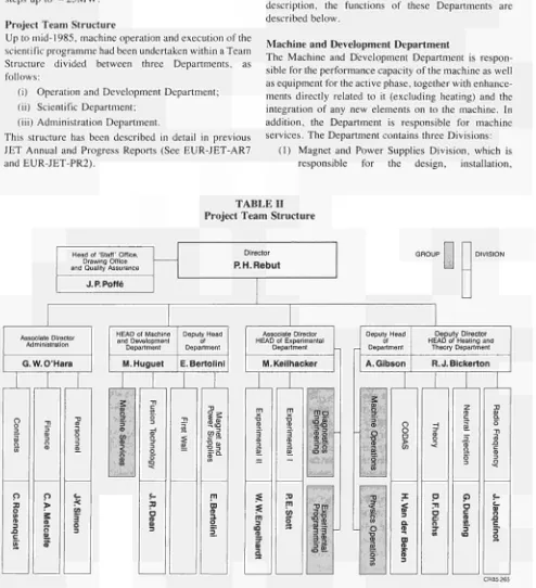
However, following the sad death of Dr H0 Wüster in mid1985 and the appointment of the new Director, Dr Ρ Η Rebut, a rationalization of the Project Structure was undertaken. The structure adopted, for management purposes was divided into four Departments (See Table II):
(i) Machine and Development Department; (ii) Experimental Department;
(iii) Heating and Theory Department; (iv) Administration Department.
The main duties of the Administration Department have been described in previous JET Annual Reports. This Report concentrates on progress made in the scientific and technical Departments during 1985. To aid this description, the functions of these Departments are described below.
Machine and Development Department
The Machine and Development Department is respon sible for the performance capacity of the machine as well as equipment for the active phase, together with enhance ments directly related to it (excluding heating) and the integration of any new elements on to the machine. In addition, the Department is responsible for machine services. The Department contains three Divisions:
[image:11.595.62.556.250.792.2](1) Magnet and Power Supplies Division, which is responsible for the design, installation,
TABLE Π Project Team Structure
Head of 'Staff' Office, Drawing Office and Quality Assurance
J.P.Poffé
Director P. H. Rebut
Associate Director Administration G . W . O ' H a r a
o o 33 O <n <B 3 O C ¡Λ o 0)
GROUP DIVISION
HEAD of Machine and Development
Department M . H u g u e t
V)
3
co Φ 2
Deputy Head of Department E.Bertolini
σ
Associate Director HEAD of Experimental
Department M. Keilhacker
ís
CO φ -a ja
as
CD O ¡S m ια iL 3i
:Ό m toI
m o —-ta 2 3 S o So "om 3 3 3 ? Deputy Head of DepartmentA . G i b s o n
O ■o ¡D e. o •α (S £
Deputy Director HEAD of Heating and
Theory Department R.J. Dickerton
Department Head
M. Huguet
Deputy Head
E. Bettolini
Fusion Technology
J.R. Dean
First Wall K.J. Dietz
Magnet and Power Supplies
E. Bettolini
Remote Handling Group T. Raimondi Remote Handling Application Group
A. Rolfe Tritium Group
W. Riediker
Machine Services Group M. Cooke
Limiter and Wall Group
To be decided
Vacuum Systems Group J.L. Hemmerich Pellet Injection Group
P. Kupschus
Magnet Group J. Last Additional Heating Power Supplies Group
R. Claesen Power Distribution Group
J. Paillère
Poloidal and Toroidal Group M. Huart
Advanced Power Supplies and Operation Group
P.L. Mondino
Fig. 2: Machine and Development Department, Group Structure (December, 1985)
operation, maintenance and modification of all power supply equipment needed by the Project. In addition, the Department is responsible for maintenance and operation of the coil systems, structural components and machine instru-mentation;
(2) First Wall Division, which is responsible for the vital area of plasma wall interactions. Its main tasks include the provision and maintenance inside the vacuum vessel of conditions leading to high quality plasma discharges. The Division develops, designs, procures and installs first wall systems and components, such as limiters, wall protections and internal pumping devices. The area of responsibility encompasses the vacuum vessel as a whole together with its associated systems, such as pumping, bake-out and gas introduction;
(3) Fusion Technology Division, which is responsible for the design and development of remote handling methods and tools to cope with the requirements of the JET device, and for maintenance, inspection and repairs. Tasks also include the design and construction of facilities for handling of tritium.
The structure of the Machine and Development Department to Group Leader level is shown in Fig. 2 and the list of staff within the Department is shown in Fig. 3.
Experimental Department
The main functions of the Department relate to the measurement and validation of plasma parameters. The main tasks are (i) to conceive and define a set of coherent measurements; (ii) to be responsible for the construction of necessary diagnostics; (iii) to be responsible for the operation of the diagnostics and the quality of measure-ments and the definition of the plasma parameters; and (iv) to play a major role in the interpretation of data.
The Department contains two Groups (on Diagnostics Engineering and Experimental Programming) and two Divisions:
(1) Experimental Division 1 (EDI), which is responsible for specification, procurement and operation of approximately half the JET diagnostic systems. EDI undertakes electrical measurements, electron temperature measure-ments, surface and limiter physics and neutron diagnostics;
MACHINE AND DEVELOPMENT DEPARTMENT
Head of Department: M. Huguet
Deputy Head of Department: E. Bettolini
D. Carre
Mrs. A. Cranstone
FUSION TECHNOLOGY
Head: J.R. Dean S.J. Booth R. Cusack Mrs. M. Daish L. Galbiati A. Galetsas E. Gebier Mrs. M.E. Jones
FIRST WALL
Head: K.J. Dietz W.P. Bailey B. Bignaux A. Boschi H. Buttgereit G. Celentano W. Daser C. Froger
MAGNET AND POWER
Head: E. Bertolini Mrs. C. Allen T. Bonicelli O. Bue D. Cacaut J. Carwardine C. Christodoulopoulos R. Claesen
J. Dobbing P. Doidge B.T. Eriksson H. Fielding J. Goff D. Halliwell M. Huart
Mrs. I. Hyde L. Nickesson
P.D. Jones A. Konstantellos A. Nowak M. Pescatore P. Presle T. Raimondi J. Removille
K. Grabenstätter L. Grobusch J. Hemmerich D. Holland G. Israel H. Jensen P. Kupschus
SUPPLIES
A. Key mer J.R. Last V. Marchese G. Marcon L. Mears A. Moissonnier P. Mondino G. Murphy Mrs. J. Nolan P. Noll J. Paillère I. Piacentini C. Raymond A. Santagiustina
Mrs. M. Rydalm M. Wal ravens
W. Riediker J. Schreibmaier L. Sonnerup A. Tesini M. Tschudin M. Wykes
G. McCarthy J. Orchard R.L. Shaw K. Sonnenberg R. Thomas E. Usselmann T. Winkel
K. Selin S. Shaw A. Skinstad S. Turley J. van Veen Ν. Walker Mrs. L.T. Wall C R . Wilson G.C. Wilson M.E. Young L. Zannelli J. Zwart
Fig. 3: Project Team Staffin the Machine and Development Department (December, 1985)
operation of the other half of the JET diagnostic systems. ED2 undertakes all spectroscopic diagnostics, bolometry, interferometry, the soft Xray array and neutral particle analysis.
The structure of the Experimental Department to Group Leader level is shown in Fig. 4 and the list of staff in the Department is shown in Fig. 5.
Heating and Theory Department
Heating and Theory Department is responsible for heating the plasma, the theory of tokamak physics, the organisation of experimental data, and the day to day operation of the machine. The main functions of the Department are (i) following the theory of tokamak physics; (ii) heating of the plasma and analysis of its effects; (iii) centralising the interpretation of experimental results and investigating their coherence; (iv) organising data acquisition and computers; and (v) preparing and coordinating operation of the machine across the different Departments.
The Department is composed of two groups (Machine Operations Group and Physics Operation Group) specifically charged with operating JET, and four Divisions:
(1) Control and Data Acquisition System Division (CODAS), which is responsible for the imple mentation, upgrading and operation of computer based control and data acquisition systems for JET;
(2) Neutral Beam Heating Division, which is responsible for the construction, installation, commissioning and operation of the neutral injection system, including development towards full power operation of the device. The Division also participates in studies of the physics of neutral beam heating;
Department Head M. Keilhacker
Experimental I P.E. Stott
Experimental II W.W. Engelhardt
Plasma Boundary Group L. de Kock Neutron Diagnostics Group
O.N. Jarvis Electron Temperature Group
A.E. Costley
Diagnostic Engineering Group P. Millward Data Processing and
Analysis Group
To be decided
Spectroscopy and Impurity Physics Group
K. Behringer Particle Dynamics Group
A. Gondhalekar Soft X-Ray Analysis Group
R.D. Gill
Fig. 4: Experimental Department, Group Structure (December 1985)
EXPERIMENTAL DEPARTMENT Head of Department: M. Keilhacker A. Ainsworth
M. Barnes
C. Caldwell-Nichols N. Foden
J. Gowman
C.J. Hancock R.C. Lobel P. Millward B. Oliver J. Reid
P.J. Roberts A. Tiscornia C.H. Wilson
EXPERIMENTAL I Head: P.E. Stott Mrs. S-J Ashwood D. Bartlett C. Best B.W. Brown D. Campbell J. Coad A. Costley J. Fessey S. Gregoli C. Gowers
P.J. Harbour M. Hone I. Hurdle O. Jarvis L. de Kock J. Källne G. Neill C. Nicholson P. Nielsen R. Prentice
P. Roach G. Sadler Miss K. Slavin A. Stevens Miss D. Strange D. Summers P. van Belle J. Vince D. Wilson
EXPERIMENTAL II Head: W.W. Engelhardt K. Behringer
G. Braithwaite J.L. Bonnerue A.D. Cheetham S. Corti
Miss G.B. Denne A. Edwards Mrs. A. Flowers R. Gill
A. Gondhalekar
J. Holm Mrs E. Källne L. Lamb G. Magyar J.L. Martin P. Morgan E. Oord J. O'Rourke A. Ravestein J. Ryan
Mrs. W. Prill B.K. Scheldt F. Sieweke Mrs. C. Simmons M. Stamp A.R. Talbot E. van der Goot M. von Hellermann B. Viaccoz
Department Head R.J. Bickerton
Deputy Head A. Gibson
Radio Frequency J. Jacquinot
Neutral Beam Heating
G. Duesing
Theory D.F. Diichs
Codas H. van der Beken
Physics Group P. Lallia Antenna Systems
A. Kaye RF Power
T. Wade
Operations Group E. Thompson Beam Line Construction Group
R. Haange Testbed Group
R. Hemsworth Control and Instrumentation
Group M. Mead
Analytic Theory Group T.E. Stringer Interpretation Group
J.G. Cordey Prediction Group
A. Taroni
Machine Operations Group B. Green Physics Operations Group
F.C. Schiiller Data Management Group
To be decided
Control Group C.A. Steed Computers Group
H.E.O. Breien Data Acquisition Group
E.M. Jones Electronics and Instrumentation Group
K. Fullärd
Fig. 6: Heating and Theory Department, Group Structure (December, 1985)
system during the different stages of its develop-ment to full power. The Division also participates in studies of the physics of RF heating;
(4) Theory Division, which is responsible for prediction by computer simulation of JET per-formance, interpretation of JET data and the application of analytic plasma theory to gain an understanding of JET physics.
The structure of the Heating and Theory Department to Group Leader level is shown in Fig. 6, and the list of staff in the Department is shown in Fig. 7.
In addition , all Divisions are involved in: • Execution of the experimental programme; • Interpretation of results in collaboration with
other appropriate Divisions and Departments; • Making proposals for future experiments.
Report Summary
HEATING AND THEORY DEPARTMENT
Head of Department: R.J. Bickerton
Deputy Head of Department: A. Gibson
K. Adams P. Chuilon A. Conway D. Cook S. Cooper T. Dale E. Daly K. Fenton B. Green
RADIO FREQUENCY
Head: J. Jacquinot R.J. Anderson J. Arbez S.C. Booth G. Bosia M. Brandon H. Brinkschulte Mrs. L. Brookes M. Bures G. Cottrell
Β. Glossop Ν. Green Α. Hancock M. Hughes H. Key P. Lomas M. Malacarne D. Pratt
Miss A. Reichenau
D.T. Edwards A. Franklin E. Hanley R. Horn G. Jessop A. Kay e P. Lallia
R. Rigley Mrs. J. Roberts Mrs. M.E. Rowe P. Rutter F.C. Schüller W. Smith A. Tanga P. Thomas
Miss J.L. Thompson
C. Maradan P. Murray J. Plancoulaine Mrs. L. Rowe F. Sand M. Schmid A.G. Sibley T. Wade C. Walker
NEUTRAL BEAM HEATING
Head: G. Duesing
H. Altmann A. Browne C. Brookes A. Burt C D . Challis D. Cooper Mrs. D. Cranmer J.F. Davies G. Deschamps A. Dines D. Ewers Η. Falter J. Gallacher
Mrs S. Gerring Α. Goede R. Haange R. Hemsworth
F. Hurd J. Jensen Α. Jones T.T.C. Jones E. Küssel D. Kausch F. Long J. Lundqvist
D. Martin P. Massmann C. Mayaux M.J. Mead W. Oben S. Papastergiou D. Raisbeck R. Roberts D. Stork E. Thompson Miss D. Vernali M. Watson
THEORY
Head: D.F. Düchs
M. Brusati J. Christiansen W. Core J.G. Cordey Mrs. S. Costar J.J. Davis A. Galway Ν.A. Gottardi
T. Hellsten Mrs. S. Hutchinson Β. Keegan
E. Lazzaro Miss M. Nave Mrs. M.G. Pacco R.T. Ross
R. Simonini E. Springmann T.E. Stringer Mrs. P. Stubberfield A. Taroni
M. Watkins J. Wesson
CODAS
Head: H. van der Beken Mrs. A.M. Bellido M.J. Botman H.E.O. Breien W.J. Brewerton M.L. Browne T. Budd P. Card
Mrs. L.M. Dines
S.E. Doding K. Fullärd R.F. Herzog E.M. Jones Miss J. Kedward G.E. Kinahan J.G. Krom Miss E. Mathiä D.S. Nassi
J.P. Nijman C G . Pollard C D . Rhoden J.J. Saffert C A . Steed B.A. Wallander J.Ε. van Montfoort I.D. Young
Section 2 sets out an overview of progress on JET during 1984 and, with a survey of scientific and technical achievements during 1984, sets these advances in their general context. This summary is specifically cross-referenced to reports and articles prepared and presented by JET staff during 1985. The more important of these articles, which are of general interest, are reproduced as appendices to this Report.
In Section 3, certain developments are considered which might enable additional improvements/ modifications of the machine to further improve its overall performance. These improvements are
con-sidered to overcome certain limitations encountered generally on Tokmaks, particularly concerned with density limits, with plasma MHD behaviour, with impurities and with plasma transport. Some attention has been devoted to methods of surmounting these limitations and these are detailed in this section.
Torus Systems
Vacuum and First Wall
During 1985, many new elements were added to the vacuum system. The second neutral injection box together with its high vacuum rotary valve and a third RF antenna were connected to the main vacuum, and a large number of new diagnostics were also installed. However, the most important developments took place in the area of the first wall. In 1985, the machine was operated for the first time with low-Z (graphite) wall protections at the inboard wall. This was the first step of a long term pro-gramme aimed at having only low-Z materials facing the plasma.
Plasma operation in these new conditions was success-ful, and from a technical viewpoint, the behaviour of the graphite tiles was also satisfactory. When the vessel was opened in July 1985 after six months of plasma operation, very little damage was seen except for some minor, but expected, signs of erosion. This contrasted with the very serious damage observed in 1984 on the Inconel protec-tion plates, even though during this operating period, the energy deposited on the graphite tiles by run-away electrons had been comparable to that during the 1984 campaign.
During the Summer shutdown period, additional graphite protection was installed to further reduce the contamination of the plasma by metal impurities. The inboard protection was extended by eight discrete poloidal rings covering the octant joints (see Fig. 8). The limiters were fitted with additional tiling to cover better their Inconel support plate at the back, since there was some evidence of plasma flowing behind the graphite tiles. At the same time, graphite tiles were also fitted at the outboard wall in the vicinity of the Octant No. 5 horizontal port, to protect the vessel wall against tangen-tial neutral beams, originating from Octant No. 8 (see Fig.9)
When operation was resumed early in 1985, the surface of the four discrete graphite limiters had been carefully cleaned. This resulted in metal free plasma dis-charges during the first 4-6 weeks of operation. How-ever, the metallic contamination already observed in 1984 returned gradually. It was not clear whether this contamination originated from sputtering during glow discharge or plasma discharges, or from metals
Fig. 8: Graphite protections covering the Octant Joints
Fig. 9: Neutral Beam protection tiles at Octant No. 5
Fig. 10: Prototype sector of the belt limiter cooling structure
of covering the walls with low-Z materials. As a result of this low Ζ policy, it was decided in July 1985 to remove from the machine the nickel-clad limiters since they represented a potential source of metallic contamination.
Discussions on tile materials for the future belt limiters resulted in the selection of graphite and beryllium, as the most likely options. Beryllium was considered as superior to graphite from the viewpoint of plasma operation, due to its very low-Z and its oxygen getter properties. However, the toxicity of the beryllium dust could complicate future in-vessel maintenance. It was decided to proceed with the procurement of both beryl lium and graphite tiles for the belt limiter (and RF antennae), and postpone until the second half of 1986 the choice of the material which would be used first.
The procurement of beryllium and graphite tiles for the belt limiter was initiated. The manufacture of the cooling structure of the belt limiter, made good progress with the completion and testing of a prototype sector (Fig. 10).
Containment of Forces During Vertical Instabilities When operations resumed in January 1985, the vacuum vessel was fitted with additional supports designed to contain the large forces acting on the vessel during vertical instabilities. Tests showed that the vessel dis placements during instabilities were effectively reduced and damped by the supports. However, these supports are only a temporary measure and are not capable of restraining safely the vessel at plasma currents in excess of 5MA, with highly elongated cross sections.
The design of a new generation of supports was con ducted in 1985. These supports will link the main vertical parts of the vessel to the magnetic limbs (Fig. 11). The interference between the new supports and diag nostics will necessitate design modifications of some diagnostics.
SKETCH SHOWING ADDITIONAL SUPPORTS OF ONE VACUUM VESSEL OCTANT
(System repeated 8 times for complete Torus)
VERTICAL P O T !
HORIZONTAL PORT
VERTICAL SUPPORT IMAX DESIGN CAPACITY « » T O N S / — PER LEG) 1
VACUUM VESSEL
EXSISTNG MAGNETIC c n c u t T SUPPORTO« COMPLETE SYSTEM
BOTTOM VERTICAL LEG ANO INERTIAL BRAKE CAPABLE OP WITHSTANDING UP TO SOO TONS VERTICAL FORCE PER OCTANT ATTACHED TO MAGNETIC CIRCUIT
ELECTPACAL NSULATION
Fig. 11: Final design of the vacuum vessel supports
Power Supply and Magnet
Systems
The main activities on the Power Supply and Magnet Systems during 1985, have been in the following areas: completion and progress in the installation of new equip ment, studies and implementation of new projects, main tenance of operation equipment and in JET Operation.
Installation and Commissioning
The 400kV/33kV substation has been extended with addition of a third 33kV busbar supplied by a new 300MVA transformer and a set of 33kV breakers: the three independent 33kV busbar systems are now opera tional.
The planned targets for the Neutral Injection Power Supplies have been achieved:
injectors have been simultaneously operated up to 60kV on the calorimeter plate and will be injected into the plasma in early 1986;
• For NI Box 2 (eight injectors), all the accelerating grid power supplies have been commissioned, while the auxiliary power supplies are under installation, for the transmission lines, the snubbers and the tower.
All the AC/DC power supplies (including auxiliaries) for the RF generators have been installed and fully commissioned: eight RF antennae can now be supplied. Three antennae have been installed in JET and up to 6MW have been coupled to the plasma.
Magnet Systems
During 1985, the toroidal field magnet was used routinely at the full design value (3.45T) of the current and of the energy dissipated per pulse. For the first time, the primary coils of the poloidal system were connected in series. This reduced the rate of use of the plasma current during the initial phase of the discharge and made it possible to utilize the full flux swing capability of the machine. Experiments in early 1985 showed that operation at full premagnetisation was still unsuccessful. The cause of the problem was identified as strong fields escaping from the saturated iron core. Experimental studies and computer field mapping suggested a number of possible remedies which will be evaluated in 1986.
For the first time in 1985, the poloidal system included the shaping circuit, to control independently the elongation of the plasma cross-section. This new circuit, which includes a part of the poloidal coils Nos. 2 and 3, was used successfully and became a permanent feature of the plasma control system.
New Projects
It has been decided to filter the voltage ripple of all JET magnet power supplies. The toroidal field filter has been installed and is now operational. However, further studies on the poloidal amplifiers are necessary to assess the optimum filter design in the various operational configurations in which account will be taken of the speed of response required for plasma control.
Orders have been placed for a new set of amplifiers (PVFA 5/6) similar in design to the existing plasma shape (PVFA 1/2) and plasma radial position control (PVFA 3/4) amplifiers. These will be used in modifying the JET magnetic configuration under consideration.
Modified design of the poloidal power supply system which makes full use of the flux swing have been defined: plasma currents up to 7MA with a flat top of several seconds and lower currents with longer flat tops, should be achievable. Contracts for the ohmic heating circuit thyristor-make switches and for the new commutating resistors have been placed. Increasing the vertical field amplifier voltage will be achieved either by a set of booster amplifiers or by additional resistors in the ohmic heating (OH) circuit. These modifications will allow the use of a relatively high loop voltage during the first
50-300ms of the current fast rise and afterwards reduce it to limit the plasma current derivative during the remaining part of the fast rise.
During the latter half of 1985, further modifications to the magnetic configuration have been considered, to reduce stray magnetic fields at breakdown and to achieve magnetic limiter configurations (X-points) at plasma currents up to 4M A. A number of circuits have been prepared and the final choice will be made in early 1986. Work on conversion of the Neutral Injection Power Supplies to 160kV is underway. Preliminary tests were performed and final implementation of the scheme has been performed on the Testbed, where satisfactory control has already been achieved up to 140kV.
During 1985, a decision was taken to reduce the number of planned RF antennae from ten to eight, as the same total power delivered to the plasma could be main-tained by replacing the existing 1.5MW RF generator tubes with a newly developed 2.0MW tube. As a con-sequence, some design modifications on the existing RF AC/DC power supplies have been required. These modifications will affect the HV diode stacks, the
thyristor controller and the output filters.
In order to correlate the performance of the power supplies with the behaviour of the 400kV grid, a computerised model has been set up. The predictions of the model, in a variety of JET operating conditions, has shown good agreement with experimental results. Thus, the model has been used to predict the reactive power compensation needs for JET, at its ultimate performance. Since the overall reactive power requirements are much above the maximum level presently allowed (375MVAR), preliminary negotiations have started with the Central Electricity Generating Board (CEGB), aimed at a permissible voltage drop above the present 1.5 %. To minimise the size of compensation equipment ultimately needed.
Preliminary consideration has also been given to possible needs for active power compensation in the event of frequent instantaneous fall of full additional heating power (due to plasma disruptions).
Maintenance and Services
The maintenance organisation for the power distribution systems and for the magnet power supplies has been operational at the three planned levels: weekly, quarterly and yearly maintenance leading to an effective improve-ment in reliability of equipimprove-ment.
A major task during 1985 was the preparation for and, during the summer shutdown,the implementation of the cabling work in the Basement. This work involved up to thirty electricians for a period of about three months, leading to the installation and/or re-routing of about 50km of cables.
Operation
year, the fast transient recorders became operational and were shown to be essential for the analysis of power supply faults. In addition, a power supply acquisition and elaboration programme is also available to assess the performance and status of the power supplies, after each pulse.
Neutral Beam Heating
System
During 1985, the main emphasis has been placed on completion of the first injector system which consists of 8 beam sources, an integrated beamline system for the eight beams, and ancillary systems of which the most important one is the cryocondensation vacuum pump. The system is designed for 10s pulse lengths and, in its present configuration, for operation with 80keV hydro gen or deuterium beams.
Major progress has also been made in component pro curement, assembly and installation for the second injector. This system is ready for commissioning the beam source power supplies and control with pretested sources installed at Octant No. 4, as soon as the power supplies become available.
Beam Sources
The beam sources for the first injector were all modified in two major aspects [1]:
• The plasma source species mix was improved (in close co-opertion with EURATOM-UKAEA Association, Culham Laboratory. UK). By superimposing a long range filter field to the original multipole magnetic field, the H + :HiH^
ratio in the extracted beams was increased from 64%:28%:8% to 84%:12%:4%;
• The 262 beamlets from a beam source are steered towards a focus in order to counteract the beamlet divergence. The steering is produced by an offset of the apertures in the deceleration grid of the extraction system. The required offset values were experimentally determined at EURATOM-UKAEA Association, Culham Laboratory, in co operation with JET, and the offset design values were corrected, the apertures of the existing deceleration grids were all re-drilled to about 50% of the original offset.
In the JET Neutral Injection (NI) Testbed, beam sources were operated at 80kV and, 60A for, 15s with hydrogen beams. By optical measurements the species mix of 80kV 41A deuterium beams were determined [2] as D^D^D*
= 82%:11%:7%.
Eight pre-tested beam sources were mounted into the injector vacuum box at the Tokamak (Fig. 12) and the final system of beam sources, power supplies, control and data acquisition were commissioned. The beam sources were operated simultaneously at 80kV and, 37A each for, 0.5s. The pulse length at this stage was limited by the capability of a provisional beam dump.
Fig. 12: First neutral injector installed at the Tokamak, showing the eight beam sources and the magnetic-shielding around the injector box, and in the foreground the HV transmission tower for the beam source supplies
Beamline System
The central part (Fig. 13) of the beamline system for the eight beams consists of a support and water supply (a ΙδΟΟπνΊΐ"1) column onto which the deflection magnets,
full-energy ion dumps, fractional-energy ion dumps and a calorimeter are mounted. The deflection magnets have water-cooled inner liners, and several fractional-energy ion dumps are mounted inside the magnets. The calori meter, which is capable of catching the eight non-neutralised long-pulse beams, is a two-gate system hinged in the midplane. When it is closed, its back panels act as beam scrapers.
This Central Column consists of four identical quad rants (Fig. 14), which each handle the beams from two sources. During 1985, assembly of the Central Column [3] was completed on site, and it was transferred into the NI Testbed (Fig. 15).
Testing of one quadrant [2] was performed using -2000 hydrogen and deuterium beam pulses of various energies (40 - 80kV) and pulse lengths (^10s). Tempera tures were measured and power density levels determin ed from the initial temperature rise and the equilibrium temperatures of thermocouples mounted 3mm below the surface of the high heat transfer components. Cooling water calorimetry was undertaken using thermocouples in the water outlets and turbine flowmeters of clamp-on ultrasonic flowmeters.
Fig. 13: Central Column of the beamline system attached to the lid of the injector box, showing the deflection magnet at the right, the full-energy ion beam dumps in the middle at the top and bottom, and the rear of the calorimeter at the left
Fig. 14: Beam entrance side of the Central Column, showing the deflection magnet apertures for the four pairs of beams, and at mid height dumps for
fractional-energy ions after a 270° deflection
beam moves by 0. Io, (b) the full beam (ion plus neutrals)
showed a constant deflection of 10 — 20mm with respect to the neutral beam which was less than that expected due to the Earths magnetic field, (c) the beamlet divergence deduced from either type of beam was 0.7°. A dis crepancy was found in the absolute values of the power densities derived from the initial temperature rise of the thermocouples during the first few 100ms (peak power
density 5.2kWcm":), which is not yet fully understood.
With the beamline system in operation, the power distribution of the extracted ion beam power was deter mined. For neutraliser line densities of 2.0 (and 1.2) xl016cm_:;, the results are shown in Table III.
The neutraliser is approximately 130mm χ 180mm in cross section and 1.8m in length. Gas is introduced into the source at a point halfway along the neutraliser length.
TABLE ΠΙ
Distribution of Extracted Beam Power
Hydrogen Beam 80kV, 4.8MW
12 (10) % 65 (70) % 20 (17) %
Deuterium Beam 80kV, 3.2MW
11 (9) % 37 (45) % 47 (45) %
Lost in source and neutraliser To beam dumps and scrapers
Would go to the plasma (minus reionisation losses in the Torus duct)
The neutraliser efficiency was determined as a relative measurement of the power onto the Testbed beam dump with and without beam deflection, and was counter checked by other measurements. The results were found to be independent of the pulse length between Is and 10s. The efficiency was calculated from the known species mix, published neutralisation crosssections and the line density determined from neutraliser pressure profile measurements (without beam). Reionisation losses were taken into account as determined from the power accountability.
Unexpectedly, agreement between the calculated and measured neutralisation efficiencies was only achieved by taking half the measured line density for the efficiency calculation (Fig. 16). Hence, it was concluded that the neutraliser line density during beamon time was only half the value measured in the absence of beam. The observation has been explained [4] as due to heating of the neutraliser gas by the beam. Fig. 17 shows the measured pressure increase in the neutraliser during a beam pulse as corresponding to a gas temperature
0.4
0.3
η 0.2
0.1
0
Neutralization data:
80kV/H2
2ΤΗ___ ■ ^0***^ ————" " "
^ χ ^ ^ ^ ^ ^ ηΤ Η incl. reionis. losses
>g> _ * '
s -
■ -'J^'î
♦ Measurements: Magnet
° Measurements with NIB Calorimeter
Species mix for ηΤ Η: 0.850/0.124/0.026
I I I
0.5 1.0 1.5 2.
CO CD CO CO rr O 0 rVgaslx 1 02 0m 2l
Fig. 16: Calculated and measured neutralisation efficiencies versus the line density measured in the absence of the beam. The discrepancy can be explained by beam heating of the neutraliser gas
increase (the gas being in the transition regime between molecular and viscous flow).
Beam profiles on the fullenergy ion dump have been determined from —70 thermocouples. In the nonbend plane, a doublehump profile along the dump surface is expected for the Vshaped dump and from a diverging beam. For 40kV H+ and 80kV D+ beams, this has been confirmed by the measurements. However, at higher energies and current'densities, discrepancies develop, and at 90kV H+ (Fig. 18), the profile is considerably wider than calculated and peaked in the apex of the dump. A similar profile change has been observed in the beam bending plane. No quantitative explanation is yet avail able for what may be due to space charge effects in the deflection magnet.
In summary, beams from individual sources in different positions have been run through the Central Column of the beamline system at:
80kV, 60A, 6s in hydrogen, 80kV, 42A, 10s in deuterium.
The unexpected beam profiles on the main ion dump have limited the pulse length of hydrogen beams to the given value, and 80kV operation is considered marginal. It appears that operation of deuterium beams at the given parameters has not reached any operational limits of the injector system.
Cryopump System
The liquid helium (LHe) refrigerator and distribution system [5] (Fig. 19) was successfully commissioned, produced 300W at 3.8K in its internal calorimeter and has now completed — 6000 hours of running time. Other cryosystem plant (eg. purifiers), He recovery, LHe
storage, and LN2 storage and supply all now operate routinely. The control of the complete plant is initiated and monitored by its programmable controller, which also updates CODAS and the central control mimic displays with relevant status data.
3
E
Δ P BEAM
Ρ Ν
20 30
Time/s
(a) Working gas: D2
60 kV. 25 A
Qs Q N
(b) Working gas: H2
80 kV, 60 A
20
Time/s
Fig. 17: Pressure at half length of the neutraliser. Tlie pressure increase during the beam pulse is consistent
with increased gas temperature
signals are transferred to the cryoplant) fails, the system switches over to a backup control.
The main operational parameters are as follows. The pump is cooled down and filled with LN2 in about 2
J .
1200
1000
1 800
| 600
400
200
_ 80
O J
I 60
i . 40
Q.
20 0
Power density profile Lower beam (el. 3) Non bend plane
Δ ^ r _ jfx *
1 I I
I
. ; là*
ΔΛ*
δ9
80 kV Hydrogen
Pulse: 8570 Δ Temp, rise * Max. temp."
N . calculated
'"""¿^ N. profile
ι ι ι
40 kV Hydrogen APulse:6756 o Pulse : 8656
5 'Pulse: 7157
Δ _
Ä calculated
profile
1 I D I CO
cd Q rx ü
300 m 4 0 0 2 0 0 0 200 400 600 mm
Distance along dump element ►
Fig. 18: Power density profile on the full-energy ion dump for 80kV and 40kV hydrogen beams. The shading gives the calculated profiles
Fig. 19: Cryosupply plant showing the refrigerator cold box in the centre, the LHe distribution box on the right and the back-up subcooler system at the rear
hours. Then, it is normally left to radiative pre-cool for 15 hours, by which time the LHe panels have reached 160K. Further cool-down and filling from the LHe supply takes another 6 hours. This cool-down procedure requires less than 10001 of LHe.
Fig. 20: Installation of the cyropump into the injector vacuum box
Pump regeneration is required when the quantity of condensed H, approaches the explosive mixture limit, in case of the occurence of a major air leak and a sudden evaporation of the condensate. The pump has been regenerated several times without problems.
Additional activity has been devoted to the cryosystem for the future Tritium Recycling System (TRS). A cryopump system was laid out and a test rig for TRS cyrocomponents was designed, built and commissioned. A tritium cryogenic transfer pump with an induction heater was designed, built and successfully tested in this rig. The rig was then handed over to the JET Tritium Group.
Injector System Tests
During the 1985 Summer Shutdown, the injector at Octant No. 8 was completed by the installation of the Central Column (improved by extension tiles to the full energy ion dumps), and the reinstallation of the neutralisers (now with Inconel hoses) and the beam sources (with additional electrostatic shields and filament stem protection caps).
The injector was then commissioned, including all associated subsystems, in a mode where the neutral beams were intercepted by the calorimeter. The beam sources were simultaneously operated in hydrogen at 60kV for pulse lengths up to 10s. No significant disturbance of the injector by the Tokamak stray fields was observed. The system was ready for injection into the Torus.
References
[ l] "JET Neutral Injection System — Status Report" G Duesing, Report JETSC22/7 (January 1985);
[2] "Operational Test of the JET Neutral Injection System in the JET Testbed" H D Falter, R S Hemsworth, G H Deschamps, Α Ρ Η Goede, Τ Τ C Jones, Ρ Massmann, M J Mead, A Stäbler, 1 lth
Symposium on Fusion Engineering, Austin, Texas, USA (November 1985), to be published; [3] "JET Neutral Injection Beamline System, Manufacture and Assembly" R Haange, H Altmann, S Papastergiou, R Β Tivey, M J Watson, llth Symposium on Fusion Engineering, Austin, Texas, USA (November
1985), to be published;
[4] "Gas Heating Effects in the Neutralisers of Neutral Beam Injection Lines" J Pamela, Report EURCEAFC 1279, CEN FontenayauxRoses (September 1985)
[5] "The JET Cryogenic Supply System" R L Roberts, A Jones, Ρ Kupschus, E Kussel, C Mayaux, M J Mead, W Obert, F Spath, C A Steed, Β A Wallender, Cryogenic Engineering Conference, Boston, USA (August 1985), to be published.
RF Heating System
1985 was as an exceptional year for the JET ICRF heating programme. The main subsystems, which had been under construction since early 1983, were assembled together for the first time; integrated within the JET apparatus and auxiliaries; and operated on the plasma. The first operation on JET was a crucial step, since it had not been possible to simulate the plasma loading. The system had been conceived on the basis of theoretical estimates of the antennaplasma coupling and could only be tested on the plasma itself. Progress was made in the following areas:
(i) Installation in the torus of two antennae and transmission lines early in 1985, followed by a third antenna in midyear;
(ii) Installation and commissioning on dummy loads of three RF generator units of 3MW output each; (iii) Conditioning of the antennae with RF power and the start of operation on the plasma, in March; (iv) Achievement of the specified net power coupled
to the plasma (half generator power) was obtained about one month after each unit was brought into service;
(v) The net power and energy coupled to the plasma reached 6MW and 15MJ by December. These combined values constituted the highest performance ever achieved with additional heating on Tokamaks;
(vi) Since May, the availability and reliability of the equipment was satisfactory and the experimental physics programme was carried out.
Fig. 21: Two of the three prototype (A0) installed in the
vacuum vessel. The three antennae coupled 6MW of power by the end of 1985 and are expected to be used during the whole of 1986
Fig. 22: Photograph of the vacuum transmission line of theA¡ antenna and its interface with the antenna. 1.5MW of net forward power should be transmitted through this reduced section
been connected to the machine. A total of eight units should be installed by the end of 1986 and connected to a new water cooled version of the antennae.
Fig. 21 shows a photograph of two of the three antennae installed in one side of the JET vacuum vessel. The antennae screens are made of overlapped nickel bars with a Τ shaped crosssection. The entire structures are protected by frames of carbon tiles, which can act as plasma limiters.
Other technical achievements have been made in the preparation for the second phase of the ICRF pro gramme, which is planned to start in 1987 with eight ICRF units each upgraded from 3 to 4MW. The upgrade will be achieved by using larger tetrodes (2MW each) in the final amplifier and new output circuits. Long pulse operation (20s) will require water cooling of the screen and forced air cooling of the vacuum transmission lines. Many components of the new antenna array have been received and testing has started with RF power on the Testbed (moved to the JET site from its previous location at EURATOMCEA Association, FontenayauxRoses, France). Important initial results have been obtained: the expected improved performance of the new double conical vacuum feedthrough (no voltage breakdown above 60kV) has been obtained and voltage standoff problems in the pressurized transmission lines have been identified. The slow development of long and tenuous whiskers in some tin plated parts of the lines gave rise to progressive deterioration of the voltage performance. Removal of the tin and some modification of the insulators led to standoff voltages in excess of 50kV.
Elements of the vacuum transmission line of the new antenna system are illustrated in Fig.22, which shows the interface between the coaxial element and an antenna. This interface, as well as the antenna itself, can be installed remotely with a telemanipulator.
1985 was a challenging year. 1986 will be devoted mainly to operation on the plasma and intensive testing of the components necessary for the next phase. 1987 should be another challenging period involving the integration and operation of eight RF units within JET.
Control and Data
Acquisition System
(CODAS)
on the machine console computer. This supervisory function includes the countdown sequences for each plasma discharge. A description of CODAS [l], and a recent review of its status [2] have been given previously. The allocation and configuration of all CODAS computers is given in Table IV, while Table V provides other quantitative data.
The main achievements during 1985 are summarised, as follows:
• Introduction of the RF subsystem in the operation of JET;
• Procurement, installation and commissioning of the Neutral Beam Injector subsystem at Octant No. 8 and preparatory work for the Octant No. 4 subsystem;
Preliminary work on the Remote Handling sub system for the master-slave tests of the articulated boom;
Upgrade and commissioning of the Plasma Fault Protection System (PFPS) to include interlocks with Neutral Beam injectors in case of low plasma current and density and improved user interface; Extension of the soft termination network facilities;
Provision of new supervisory software to standardise the countdown sequence and provide easier subsystem operation in stand alone mode for commissioning periods;
Upgrade of operating system to release J of SIN-TRAN to benefit from its improved efficiency;
TABLE IV
CODAS Computer Configuration at the end of .1985
Subsystem AH* AS CA* CB CP DA* DB* DC* DD* DE* DF* DG EC* EL GS* HL* MC* PF* RB* RF* RH SA* SB SD SS* TB* TP* TR TS VC* YB YC YD YE Usage
NI Additional Heating Assembly Database Message Switcher A Message Switcher Β Cable Database On-line diagnostic On-line diagnostic On-line diagnostic On-line diagnostic Off-line diagnostic On-line diagnostic Diagnostic Commissioning Experiment Console Electronic General Services Harwell Link Machine Console Poloidal Field
Radio Frequency Test Bed Radio Frequency
Remote Handling Storage & Analysis Standby-System/Backup Built-in, Pool, Computer dB Safety & Access
NI Test Bed Toroidal Field Tritium Test Vaccum Integration CODAS Commissioning/NIB-C Sc Dpt Development
CODAS Development Model ND100 Compact ND100 ND100 ND530 ND520 ND520 ND520 ND520 ND520 ND520 ND520 ND570 ND100 ND100 ND100 ND100 ND100 ND100 ND100 ND100 ND560 ND100 Compact ND100 ND530 ND100 ND100 ND100 ND100 ND530 ND100 ND570 ND520 Memory (MByte) 2.0 0.75 0.5 0.5 5.0 3.0 3.0 3.0 3.0 3.0 3.0 5.0 5.0 1.0 1.5 1.5 1.5 2.0 1.5 1.5 1.5 3.0 1.5 0.75 1.5 3.0 1.5 1.5 1.5 2.0 3.0 1.5 5.0 5.0 Disks (MByte) 1x75 1x45 1x75 1x75 1x75 1x288 2x75 1x75 1x288 2x75 2x75 2x75 2x75 2x75 1X75 1x288 1x75 1x75 1X75 1X10⁸ 1x75 1X75 1X75 1X75 1X75 1X75 1x288 2 x 7 5 2 x 1 0 1x288
1x45 1X75 2X75 1x75 1x75 1x28 1x75 1x75 2x75 1x75 1x75 1x28 2x75
TABLE V
Quantitative Information on CODAS Installation at end of 1985
CODAS Interface Cubicle CAMAC Crates
CAMAC Modules
Eurocard Modules (Signal Conditioning) Computer Terminal
CAMAC Serial Loop (Fibre Optic) On-line Computers
Off line and Commissioning Computers Size of JPF
Number of diagnostics on-line with CODAS Number of diagnostics under
commissioning with CODAS
113 187 2,953 5,739 151 22 20 14 6.6MB 15 8
• Substantial improvements were made on the following packages:
(i) Alarm handling;
(ii) Waveform generation and selection; (iii) Flywheel generator converter, static units,
circuit breakers support software; (iv) Gas introduction
(v) Cryo-system and Helium plant monitoring and control;
(vi) Access control.
Continuous development of automated pro-cedures to relieve the operation team from tedious tasks and to implement sequences which have been tried and tested by the operation team. Study of data throughput improvements and, as a first phase, installation and Commissioning of a Hyperchannel link between Harwell and JET; Complete revision and recommissioning of all existing CISS PLC's and addition of PLC's for Neutral Beam, Neutral Beam Testbed, RF and a second supervisor;
Design, commissioning and installation of a serial link between the CISS PLCs and CODAS computers to improve fault condition diagnostics; Design, manufacture, installation and com-missioning of 15 CODAS interface cubicles; Installation of 800 additional transient recorder channels to investigate transient and fault conditions;
Development of a coherent set of user friendly hardware test programs;
Re-configuration of the physics terminal room to match operation requirements;
Release to users of the cable management data base which contained 800,000 records by the end of 1985;
TABLE VI
Review of CODAS Electronics Stock Holding (Installed, Pre-procurement and Spares)
1. CAMAC system modules 2. CAMAC digital I/O modules
3. Timing system (CAMAC & Eurocard) 4. CAMAC analogue I/O modules 5. CAMAC display modules 6. CAMAC Auxiliary controllers 7. CAMAC powered crates 8. U-port-adaptor
9. CISS modules 10. CCTV 11. Cubicle frames
12. Console devices (not CAMAC) 13. Power supply modules
14. Intercom, Public Address, Computer terminal network 15. Pool
16. Analogue I/O in Eurocard 17. Digital I/O in Eurocard 18. Eurocard sub-racks
TABLE VII
Status of JET Diagnostic Systems Diagnostic System KBl KCl KEI KE3 KGl KG2 KG3 KHI KH2 KJt KK1 KK2 KLI KMI KM3 KM4 KM2 KM5 KNl KN2 KN3 KN4 KP1 KR1 KS1 KS2 KS3 KS4 KT I KT2 KT3 KT4 KX1 KYI KY2 KY3 KZI Diagnostic
Bolometer Scan Magnetic Diagnostics Single Point Thomson Scattering Lidar Thomson Scattering Multichannel Far Infrared Interferometer and Polarimeter Single Channel Microwave Microwave Reflectometer
Hard Xray Monitors Xray Pulse Height Spectrometer Soft Xray Diode Arrays Electron Cyclotron Emission Spatial Scan Electron Cyclotron Emission Fast System Limiter Surface Temperature
2.4 MeV Neutron Spectrometer 2.4MeV TimeofFlight Neutron Spectrometer 2.4MeV Spherical Ionisation Chamber 14MeV Neutron Spectrometer 14MeV Neutron Spectrometer Time Resolved Neutron Yield Monitor Neutron Activation Neutron Yield Profile Measuring System Delayed Neutron Activation Fusion Product Detectors Neutral Particle Analyser Array Active Phase Spectroscopy Spatial Scan Xray Crystal Spectroscopy Ηalpha and Visible Light Monitors Active Beam Diagnostics (using heating beam) VUV Spectroscopy Spatial Scan VUV Broadband Spectroscopy Visible Spectroscopy Grazing Incidence Spectroscopy High Resolution Xray Crystal Spectroscopy Surface Analysis Station Surface Probe Fast Transfer System Plasma Boundary Probe
Pellet Injector Diagnostic
Purpose
Time and space resolved total radiated power
Plasma current, loop volts, plasma position, shape of flux surfaces 7" and n, at one point several times
Τ and n, profiles
(1) jrtrds on 7 vertical chord and 3 horizontal chords
(2) }nfBpds on 6 vertical channels jn»(r)ds on 1 vertical and 3 horizontal chords in low density plasmas ( < 1 0i am "3)
n, profiles and flucutations
Runaway electrons and disruptions Plasma purity monitor and
T, on axis MHD instabilities and location of rational surfaces
Tt (r,t) with scan time of a few milliseconds
7', (r,t) on microsecond time scale (i) Monitor of hot spots on limiter
and RF antennae {ii) Temperature of wall and
limiter surface
Neutron spectra in DD discharges, ion temperatures and energy distributions
Neutron spectra in DT discharges, ion temperatures and energy distributions
Time resolved neutron flux
Absolute fluxes of neutrons Space and time resolved profile of neutron flux Absolute fluxes of neutrons Charged particle produced by fusion reactions
Profiles of ion temperature impurity behaviour in active conditions Space and time resolved impurity density profiles Ionisation rate, /,.... Impurity fluxes
Fully ionized light impurity concentration
Ti(r) rotation velocities Time and space resolved impuritiy densities Impurity survey
Impurity fluxes from wall and limiters Impurity survey
Ion temperature by line broadening
Plasma wall and limiter interations including release of hydrogen isotope recylcing
Vertical probe drives for electrical and sur face collecting probes
Particle transport, fueling
Association
IPP Garching JET Risø
JET and Stuttgart University CEA Fontenayaux Roses
JET and FOM Rijnhuizen JET JET
JET JET IPP Garching NPL, Culham Lab. and JET FOM, Rijnhuizen JET and KFA Jülich
UKAEA Harwell
NEBESD, Studsvik
KFA Jülich UKAEA Harwell NEBESD, Gothenberg UKAEA Harwell UKAEA Harwell UKAEA Harwell Mol
JET ENEA Frascati IPP Garching IPP Garching JET JET
CEA Fontenayaux Roses
UKAEA Culham Lab. JET
UKAEA Culham Lab. ENEA Frascati IPP Garching UKAEA Culham Lab. JET
UKAEA Culham Lab. IPP Garching
Status Dec. 1985
Operational (1) Operational (2) Enhanacement Operational Construction (1) Operational (2) Under construction 2 mm Operational Extension to 1mm (1) Prototype system operating (2) Multichannel system being designed Operational Installed Operational Operational Operational Operational Development Construction proceeding Commissioning Commissioning Design completed Decision on construc tion under review Operational Installation Construction proceeding Awaiting delivery Prototype operational Upgrade
Operational Under construction Under construction Operational Poloidal Scan Provisional system Under construction Operational Operational Operational Under construction Installed Commissioning Commissioning Both units installed
IPP Garching ι Partly installed
Date of Operation
in JET
Mid 1983 partly Early 1984 fully Mid 1983 Late 1985 Mid 1984 Early 1987 Mid 1984 partly Early 1985 fully Early 1987 Mid 1983 Not proceeding Mid 1983 Mid 1987 Mid 1983 Early 1986 End 1985 Late 1985 Early 1985 Mid 1984 1986 1986
1986
1986
Mid 1983 1986 1986 1986 1985 1986 Mid 1984 partly End 1985 fully Mid 19S6 Early 1986 Early 1983 Early 1986 Early 1986 Early 1987 Mid 1985 Early 1984 Mid 1983 Early 1986 Early 1986 Mid 1986 Mid 1986 Mid 198486