This is a repository copy of Th gme 10: A numerical model to capture the geotechnical
response to coal combustion at an underground coal gasification site.
White Rose Research Online URL for this paper:
http://eprints.whiterose.ac.uk/109384/
Version: Accepted Version
Proceedings Paper:
Ekneligoda, TC, Yang, LT, Wanatowski, D et al. (2 more authors) (2015) Th gme 10: A
numerical model to capture the geotechnical response to coal combustion at an
underground coal gasification site. In: 2nd EAGE Workshop on Geomechanics and
Energy: The Ground as Energy Source and Storage. Second EAGE Workshop on
Geomechanics and Energy, 13-15 Oct 2015, Celle, Germany. , pp. 30-34. ISBN
9781510814202
[email protected] https://eprints.whiterose.ac.uk/ Reuse
Unless indicated otherwise, fulltext items are protected by copyright with all rights reserved. The copyright exception in section 29 of the Copyright, Designs and Patents Act 1988 allows the making of a single copy solely for the purpose of non-commercial research or private study within the limits of fair dealing. The publisher or other rights-holder may allow further reproduction and re-use of this version - refer to the White Rose Research Online record for this item. Where records identify the publisher as the copyright holder, users can verify any specific terms of use on the publisher’s website.
Takedown
If you consider content in White Rose Research Online to be in breach of UK law, please notify us by
A numerical model to capture the geotechnical response to coal combustion at an underground coal gasification site
Ekneligoda, T.C.,1*, Yang L.-T.1, Wanatowski D.2, Marshall A.M.1, Stace, L.R.1
1 Nottingham Centre for Geomechanics, University of Nottingham, Nottingham, UK
2 Faculty of Science and Engineering, University of Nottingham, Ningbo, China
Introduction
Underground coal gasification (UCG) offers a significant potential contribution to future energy demand. The process allows obtaining energy in the form of syngas from a thin coal seam that cannot be extracted by conventional methods. According to Bhutto et al. (2013), UCG is a combination of mining, exploitation and gasification that eliminates the need for conventional mining techniques including human involvement and can be used in deep or steeply dipping, un-mineable coal seams.
Though UCG was first tried as early as 1868 by the German scientist Sir William Siemens, it was not industrialized as very few detailed research studies had been carried out on UCG. In 1909, Anson G. Betts obtained the patent for UCG. The first UCG field test program was carried out by Ramsey in England in 1912 (Bhutto et al., 2013) with more extensive trials in North Derbyshire in the late 1950’s (National Coal Board 1964).
The UCG process not only offers a more environmentally friendly energy source compared to traditional coal mining energy but also provides a sub-surface cavity that could potentially be used for
the storage of CO2 (Sarhosisa et al., 2013). Also, as the coal is gasified in-situ, generation of mining
related waste is minimised compared to traditional mining (Naghouni, 2013; Imran et al., 2014;
Shirsat, 1989).
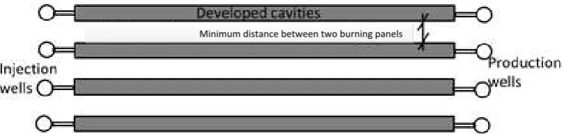
[image:2.595.95.500.483.584.2]The industrial application of UCG is carried out with several parallel burning panels, as illustrated in Figure 1, which enhances the gas production considerably compared to a single panel. One of the major concerns of parallel burning is the induced ground subsidence. The selection of distance between parallel burning panels should be made after a thorough study of the effect of the coal burning process on ground subsidence.
Figure 1- Multi-panel industrial application of UCG
A UCG field study carried out at the Wieczorek mine, Poland, in 2014 was used as the basis of the numerical analyses described in this paper. The numerical analyses were conducted in two stages. The stage1 numerical model included a section near the UCG panel which was assigned a coupled thermal-mechanical constitutive relationship. This model can capture various important features of the
UCG process, including the geotechnical situation during in-situ coal burning, the variation of
temperature in the cavity, a gradually decaying energy emission, either forward or backward movement of the burning head, and temperature dependent material properties (Ekneligoda et al., 2015). Stage 2 involved a similar but more computationally efficient mechanical-only numerical
model that incorporated results of maximum cavity size from stage 1 in order to evaluate the worst
Numerical models
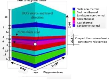
A three dimensional model representing the geological cross section at the Wieczorek site in Poland was created in FLAC-3D (Figure 2). In the stage 1 analysis, a model extending from a depth of 395m
(Z=94m) to 489m (Z=0m) was used, with a section from Z=24.5–to 45m (total height of 20.5m) assigned the coupled thermal-mechanical constitutive relationship (Figure 2) in order to simulate the
[image:3.595.201.393.252.392.2]coal burning process. This was done by modifying the energy balance equation and adding an additional term as a source that relates to the calorific value of coal. To account for the fact that the energy release from coal gradually decreases with time, the source term was given as a time decaying function. The mechanical degradation of coal due to burning was carried out by removing the burnt zone from the calculation. The zone was removed after one hour from ignition. The temperature dependent material properties were assigned to the coupled analysis according to the experimental data provided by Ranjith et al. (2012).
Figure 2- Details of geological profile used in FLAC3D model (stage 1 dimensions)
The additional stress component due to heat transfer is coupled to the stress calculation. It is important to note that the coupling occurs only in one direction. Therefore mechanical stress change does not affect the temperature rise, but the temperature rise affects the mechanical stress change. The coupled equation can be presented in simple form as in Eq 1. Assuming that the thermal expansion/contraction is isotropic, the stress–strain relationship for a non-isothermal material can be
presented as;
= 2 + 2
3 3 (1)
where G = E/2(1 +), K = E/3(1 – 2) and
kk =
11 +
22 +
33.
ij is the component of the totalstress tensor,
ij is the component of the total strain tensor, Gis shear modulus, Kis bulk modulus, Eis Young’s modulus, is Poisson’s ratio,
ij is the Kronecker delta, T the temperature, and
T isthe thermal expansion coefficient.
The equations of equilibrium and the strain–displacement relations can be expressed as
ij,j+ fi =0 (2)
ij = ½( ui,j+uj,i) (3)where fi and ui (i = x, y, z) are the components of the net body force and displacement in the i
-direction, respectively. A comma followed by subscripts represents the differentiation with respect to spatial coordinates and repeated indices in the same subscript imply summation over the range of the indices (generally 1–3, unless otherwise indicated) (Detournay, 1993; Zhang, 2008).
In the stage 2 analyses, the lateral dimensions (X and Y) of the model illustrated in Figure 2 were modified in order to ensure boundary effects on measurements of displacements were minimized. For the single panel analysis, the lateral dimensions were increased to X=110m and Y=120m; for the
Z
=
9
4
Dimension in m
2
0
.5 Coupled thermal-mechanical
constitutive relationship
395m to the ground surface
X=10 0 y=60
6 11 6
1.5 6
8 28
2 4
14 7
Origin
multiple panel analyses they were increased to X=200m and Y=120m. The total height of the model was maintained at 94m for both single and multiple panel analyses. This model used standard mechanical constitutive relationships in order to decrease the computational time required to obtain results. Analyses were conducted to evaluate ground movements for worst-case UCG scenarios for
single and multiple panels. This model was deemed to represent the worst-case scenario because it
included an estimate of maximum cavity size after long term burning (based on stage 1 results) and also because it does not redistribute stresses gradually with excavation.
Results
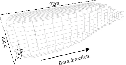
In this study (stage 1) it was found that maximum temperature within the mesh was always less than 1000oC (Ekneligoda et al., 2015). The burning zone in the numerical model spread 7.5m
perpendicular to the burning direction in the horizontal plane and 5.5m in the vertical direction after 20 days of burning. The numerically predicted cavity after 20 days of burning is illustrated in Figure3.
In the stage 2 analysis, the worst-case scenario of single cavity development was simulated by
removing a region of the coal layer 60x12x6m all at once. The longest dimension of 60m was selected to account for uncertainty associated with the movement of the burning head and to ensure a worst
-case scenario was considered. The ground subsidence measured at the top of the model (395m below the real ground level) was 23mm directly above the cavity and 5mm at a distance 100m (in X
[image:4.595.197.403.347.453.2]-direction) offset from the cavity centerline.
Figure 3 – Stage 1 analysis results: cavity development after 20 days
Additional stage 2 analyses were conducted in which 5 and 7 burning panels were removed instantaneously from the model. The ground subsidence was evaluated for different distances between panels, ranging from 5m to 20m (edge to edge distance) in steps of 5m. The subsidence above the center point of the gasification panels was 72mm and 88mm for the 5 and 7 parallel burning models, respectively, for a spacing distance of 5m (Figure 4). Gradually deceasing ground subsidence was observed at the center point of the gasification panel’s arrangement by increasing the distance between the burning coal panels.
[image:4.595.98.467.589.730.2](a) five burning panels (b) seven burning panels Figure 4- Variation of subsidence with panel spacing
22m
5. 5m
7.5m
Burn direction
5 10 15 20
0 10 20 30 40 50 60 70 Sub si d e n ce me a su re d a t 3 9 5 m b e lo w t h e su rf a ce (mm)
Minimum distance between two burning panels(m) Subsidence vertically
above the gasification point Subsidence 100m from gasification point
5 10 15
0 10 20 30 40 50 60 70 80 90 Sub si d e n ce me a su re d a t 3 9 5 m b e lo w t h e su rf a ce (mm)
Minimum distance between two burning panels(m) Subsidence Vertically
Conclusions
A numerical model was presented considering several features that take place in the underground coal gasification process. The maximum temperature during the gasification process was estimated to rise to 1000oC inside the cavity. The maximum dimension of the cavity was 22m in the burning direction,
7.5m perpendicular to the burning direction (lateral direction) and 5.5m in the vertical direction after 20 days of gasification. A worst-case scenario study showed that the maximum displacement directly
above the gasification point at the top of the mesh (at a depth of 395) was 23mm and reduced to 5mm at a distance 100m away from the panel.
The ground induced subsidence at the top of the numerical model (a depth of 395m) varied from 72mm to 42mm directly above the gasification point (at the center point of the gasification arrangement) when the minimum distance between panels was varied from 5m to 20m for the 5 burning panel model; the equivalent maximum ground subsidence ranged from 85mm to 50mm for the 7 burning panel model.
Acknowledgements
The research was conducted within the research project: Underground Coal Gasification in operating mine and areas of high vulnerability (COGAR) funded by the European Commission Research Fund for Coal and Steel (RFCS) (Project No. RFC-PR-12005).
References:
Bhutto A. W., Bazmi A. A., and Zahedi G., 2013. Underground coal gasification: From fundamentals to applications. Progress in Energy and Combustion Science, 39(1), p.189-214.
Detournay E., Cheng A.H.D., 1993. Fundamentals of poroelasticity. In: Fairhurst C, editor. Comp rock eng, vol. 2. Oxford: Pergamon; p. 113–71.
Ekneligoda T.C., Yang L.-T., Wanatowski D., Marshall A.M., and Stace, L.R., 2015. A fully developed thermal-mechanical coupled numerical model to capture spontaneous coal combustion and its effect at Wieczorek site in Poland, 7th international conference on mining sciences and technology, Xuzhou, China, April 26-27,2015.
Imran M., Kumar D., Kumar N., Qayyum A., Saeed A., and Bhatti S. M., 2014. Environmental concerns of underground coal gasification, Renewable and Sustainable Energy Reviews, 31, p. 600–610.
Naghouni A.F., 2013. CO2 Sequestration in UCG, PhD thesis, University of Calgary, Alberta.
National Coal Board 1964. The Underground Gasification of Coal., Sir Isaac Pitman and Sons London.
Ranjith P.G., Daniel R., Bai J. C., Samintha M., and Perera A., 2012. Transformation plasticity and the effect of temperature on the mechanical behaviour of Hawkesbury sandstone at atmospheric pressure. Engineering Geology, No. 151, p.120–127.
Sarhosisa V., Yangb D., Shengb Y., and Kempk T., 2013. Coupled hydro-thermal analysis of underground coal gasification reactor cool down for subsequent CO2 storage, Energy Procedia, 40: p.428 – 436.
Shirsat A.V., 1989. Modelling of cavity growth in underground coal gasification. MSc Thesis, Master of Science in Chemical engineering, Texas Tech University.