RADIONUCLIDE MIGRATION IN PLUTONIC ROCKS:
IMPLICATIONS FOR HIGH-LEVEL NUCLEAR WASTE DISPOSAL.
Vanessa Ann Guthrie B.Sc. (Hons.) Dip. Nat. Res.
submitted in fuIfillment of the requirements for the degree of Doctor of Philosophy.
University of Tasmania Hoban, Tasmania.
This thesis contains no material which hasbeen acceptedfor the award of any other higher degree or graduate diploma in any tertiary institution, and to the best ofmy
knowledge and belief, no copy or paraphrase ofmaterial previously written or published by another person, except where due reference is provided.
It is our responsibility to ensure that we leave for our children the environment which we hold in trust not as a legacy
Abstract
Geochemical studies of deeply buried intrusive rocks provide the foundation for evaluating the suitability of crystalline rocks as repositories for solidified High Level Nuclear Waste (HLW). This geochemical study examines the migration of natural and introduced radionuclides during interaction between groundwater and plutonic rock, to provide an understanding of the processes which may operate in the potential repository environment.
Rock cores from the Coles Bay Granite (Tasmania), Kambalda Granodiorite (Western Australia) and the Roxby Downs Granite (South Australia) were selected for this study on the basis of the variation in mineralogy, fracture density and degree of alteration. Firstly, the behaviour ofU- and Th-decay series radionuclides in each rock was investigated as a natural analogue for some HLW elements to identify the nuclide migration pathways and significant sites of rockJradionuclide interaction. Secondly, Synroc doped with actinides and fission products was used as a source of radionuclides to evaluate the interactions between waste elements and intrusive rocks in a simulated water-saturated repository environment. This integrated approach has identified the mechanisms controlling radionuclide release, migration and retention.
11
dominant nuclide migration pathways and the most significant sites of rock/radionuclide interaction are the secondary and fracture-in filling minerals.
Leach testing of Synroc with the three intrusives was carried out to determine the mechanisms and processes which occur during Synroc/water/granitic host rock interaction. Significant geochemical and mineralogical changes were observed in all three intrusives during leach testing, including loss of crystal structure and formation of surface reaction products. These changes are reflected in a change in the leach solution conditions and may also affect the distribution of radionuclides during leach testing. The presence of the intrusives significantly inhibited the total release of the actinides (Np, Pu and Cm) and the less soluble fission products (Zr, Ce, Nb and Ru) from Synroc, as a result of the change in solution chemistry and nuclide solubility induced by the presence of the granites. Substantial preferential uptake of all radionuclides by specific secondary and fracture infilling minerals (such as sericite, hematite, Fe- and Ti-oxides/hydroxides) in intrusives was also observed, which was controlled by rapid ion exchange, redox reactions, sorption and surface deposition of colloids and pseudocolloids.
iii
Acknowledgements
To see the completion of this thesis is the fulftllment of a dream. Many people have assisted me in the progress of this work, have believed in my capabilities at times when I did not believe in them myself, and have consistently and unstintingly given of themselves throughout the duration of the work. I would like to thank all of these people, and in particular;
• at the Australian Institute ofNuclear Science and Engineering;
Roger Gammon, and his predecessor, Bill Palmer, for their enthusiasm and encouragement of my work,
• at the Australian Nuclear Science and Technology Organisation;
Des Levins, for his enthusiasm, guidance and insight in establishing the project, and encouragement and support of me to persevere
Kaye Hart, for her scientific ability, understanding and patience in teaching me in the face of all confusion, her constant encouragement to me to continue and, not least of all, her friendship and support
Kath Smith, for her time and effort spent in patient explanation, her guidance in TEM techniques and her friendship
Brian Seatonberry, for his ability to make sense of my garbled notes and assistance in producing consistent results
Adam Jostsons, for his interest in and encouragement of the project from its inception.
Others who have offered their assistance without question include Sue Brown, John Warmeant, Brett Robinson, Roy Warren and Dim Roman. Many thanks.
• at the University ofTasmania;
iv
earlier versions of each chapter, and for his ability to ask curly questions when you least expect them
Russell Sweeney and Graeme Wheller, for their efforts spent in reading some early drafts of both papers and chapters
Rick Varne, for his time and effort in seeing my thesis through the mill Dave Green, for his continued interest and encouragement of this work and my professional career
Garry, Steve, Michael and June, for their friendship and constancy, and the other post-graduate students and post-doctoral fellows of the Department of Geology for their interest and support. You know who you are - thanks.
Access to core samples was arranged by staff of the Tasmanian Department of Mines, and Western Mining Corporation -Kambalda Nickel Operations and Olympic Dam Project. In particular, I wish to thank Ken Cross, for his time and effort in arranging access to samples at Olympic Dam, and reviewing earlier drafts of papers and chapters.
This work was undertaken while I was in receipt of an AINSE studentship, without which the work would never have been completed. Western Mining Corporation and Australian Nuclear Science and Technology Organisation, Materials Division and Chemical Engineering Section also provided financial and logistic support for which I am very grateful. Papers arising from this work have been published with the kind permission of AINSE, ANSTO and WMC - Olympic Dam Project and Kambalda Nickel Operations.
i Table of Contents
Abstract.
Acknowledgements Ill
SECTION I: INTRODUCTION AND BACKGROUND
Chapter 1: The Nuclear Waste Disposal Problem
1.1 Introduction 1:1
1.2 Background 1:2
1.2.1 The Fundamental Problem - Nuclear Waste 1:2
1.3 Geological Disposal ofHLW 1:6
1.3.1 The Multiple Barrier Concept. 1:8
1.3.2 The Geological Barrier 1:10
1.4 Aims and Objectives of this Study .1:14
Chapter 2: Regional Geology
2.1 Granites in the High-Level Waste Disposal Environment 2:1
22 Sampling Techniques and Analytical Methods 2:4
2.3 Coles Bay Granite 2:9
2.3.1 Field Relationships 2:9
2.3.2 Petrography 2:10
2.3.3 Whole Rock Geochemistry 2:15
2.4 Kambalda Granodiorite ~ 2: 18
2.4.1 Field Relationships 2: 18
2.4.2 Petrography 2:20
2.4.3 Whole Rock Geochemistry 2:24
2.5 Roxby Downs Granite 2:28
2.5.1 Field Relationships 2:28
2.5.2 Petrography 2:30
2.5.3 Whole Rock Geochemistry 2:34
SECTION 11: THE BEHAVIOUR OF NATURAL URANIUM
AND THORIUM IN GRANITES
Chapter 3: Fission-Track Analysis of Uranium Distribution in Granites
3.1 Introduction 3:1
3.2 Analytical Methods 3:1
VI
3.3 Results: Fission-track Mieromapping 3:4
3.3.1 Background U 3:9
3.3.2 Resistate U 3:9
3.3.3 Secondary U 3:16
3.3.4 Fracture U 3:21
3.4 Discussion 3:24
3.4.1 Primary Uranium Distribution 3:24
3.4.2 Secondary Uranium Distribution 3:26
3.5 Conclusions 3:32
Chapter 4: The Use of Uranium-Series Disequilibrium Studies
to Determine Recent Rock/Groundwater Interactions in
Granites
4.1 Introduction 4: I
4.1.1 Naturally Occurring Radioactive Decay Series - the
Uranium-Decay Series 4: I
4.1.2 Geochemistry of the U-Decay Series and the Occurrence of
Radioactive Disequilibrium 4:5
4.1.3 Application of U-Series Disequilibrium Studies as a Natural
Analogue of the HLW Disposal Environment. 4: 8
4.2 Characterisation of U-Series Disequilibrium in Three Australian
Granites 4:9
4.2.1 Experimental Methods 4:9
4.2.2 Results - U-Series Disequilibrium Analysis 4:10
4.3 Mechanismsfor Isotopic Fractionation .4:19
4.4 Implications for HLW Disposal .4:25
4.5 Conclusions .4:26
SECTION III: AN INTEGRATED STUDY OF THE INTERACTION BETWEEN SYNROC AND GRANITE
Chapter 5: Alternative Wasteforms for HLW Disposal
5.1 Introduction to Wasteforms - Previous Work 5:1
5.2 Synroc as a Wasteform Aiternative 5:2
5.2.1 Chemical Durability 5:3
5.3 Comparative Behaviour of Synroc and Borosilicate Glass 5:8
Chapter 6: The Crystalline HLW Repository Environment
6.1 Factors affecting Radionuclide Migration in the Crystalline Repository
vii
6.2 The Behaviour ofGranites as a PotenriaL DisposaL Medium 6:3
6.2.1 Experimental Procedure 6:3
6.2.2 Granite Behaviour under Leach Conditions 6:4
6.3 Discussion 6:22
6.4 Conclusions 6:25
Chapter 7: Simulation of Repository Processes I: Tile Interaction of Granite and Synroc doped with the
Actinides
7.1 Introduction - Previous Work
> 7:1
7.2 ExperimentaL Techniques 7:3
7.3 ResuLts 7:6
7.3.1 239pu 7:8
7.3.2 237Np 7:15
7.3.3 244Cm 7:20
7.4 Discussion 7:25
7.4.1 Mobilisation of 239Pu, 237Np and 244Cm from Synroc 7:25 7.4.2 Mechanisms for 239pu, 237Np and 244Cm Distribution 7:27
7.5 Conclusions 7:30
Chapter 8: Simulation of Repository Processes 1I: The Interaction of Granite and Synroc doped with Mixed Fission Products
8.1 Introduction - Previous Work 8:1
8.2 Mixed Fission Products 8:4
8.2.1 Experimental Techniques 8:4
8.2.2 Results 8:6
8.3 Uptake of134Cs and 90SrfromRadionucLide-Doped SoLution 8:17
8.3.1 Experimental Techniques 8:17
8.3.2 Results 8:19
8.4 Discussion 8:30
8.4.1 Solution Characteristics 8:30
8.4.2 Mechanisms for Retention of Radionuclides by Granites 8:32
viii
SECTION IV: IMPLICATIONS AND CONCLUSIONS
Chapter 9: Implications for HLW Disposal
9.1 The Repository Environment - an Integrated Study ...•... 9: 1 9.2 Natural Analogues - What information can they provide? 9:4 9.3 The Three Component Simulation of the Repository Environment
Processes 9:6
9.4 Repository Assessment and Predictive Model Validation 9: 10 9.5 Granites as a Candidate Repository Medium 9:13
9.6 Future Research arising from this Study 9:15
Chapter 10: Conclusions
10.1 Conclusions arising from this Study 10:1
SECTION V: REFERENCES AND APPENDICES
References
R:1
SECTION I
Chapter 1
The Nuclear Waste Disposal Problem
1.1 Introduction
One of the key environmental issues facing the scientific community today is toxic waste disposal. Of the many types of toxic and chemical wastes which present a potential hazard to both the environment and mankind (i.e. the biosphere), the most challenging is that containing radioactive material. In particular, the intensely radioactive high-level nuclear wastes (HLW) which arise from nuclear power production require unique conditions of disposal, such as remote handling and isolation for extremely long time periods. Today's society also expects that once disposal of such wastes has been undertaken, isolation should be complete and total, and the consequences of this disposal in the environment should no longer be apparent
INTRODUCTION 1:2
through the environment and their interactions with the host rock, be more fully understood before permanent disposal is undertaken.
Current international earth science research into HLW disposal is focussed on evaluating these processes so that a safe and predictable disposal environment may be developed and utilised in the near future. Whereas the need for a HLW disposal policy in Australia is far less pressing than in many other countries, it is nevertheless important and of benefit to our future community that the questions posed by HLW disposal be addressed, and that the environmental consequences be understood. This study aims to contribute to this understanding through the evaluation of the geochemical mechanisms and processes which may exist in the disposal environment.
1.2 Background
1.2.1 The Fundamental Problem - Nuclear Waste
The nuclear (or radioactive) wastes for which long-term disposal is considered are produced at all stages of the nuclear fuel cycle. These cover a wide spectrum of solid, liquid and gaseous wastes which range from low to extremely high levels of radioactivity and long-lived radionuclides as can be seen in Figure 1.l.
Nuclear wastes may be separated into five descriptive categories on the basis of their degree of radioactivity;
• effluents which are of sufficiently low radioactivity that they may be discharged directly into the environment where they dilute and disperse
• low-level wastes (LLW) which are usually of low radioactivity that are generated at all stages of the nuclear fuel cycle and include mine and mill tailings and waste solutions, gaseous releases and solid materials from fuel fabrication and reactor operations
INTRODUCTION 1:3
• a-bearing wastes which are moderate volumes of low- and intermediate-level wastes contaminated with high-activity a-emitting material such as Pu, and include ion exchange resins, fuel cladding and storage pond residues
• high-level wastes (Ill..W) are low volume, extremely radioactive materials produced during reactor operation and reprocessing. There are two principal types of HLW; solidified wastes from fuel reprocessing and spent fuel rods. Solidified wastes are composed principally of low volatility fission products, small amounts of U and Pu (typically
<
1%) which are not extracted during reprocessing, plus other transuranic elements produced during reactor operation, including Np, Cm and Am. On the other hand, spent fuel rods contain much higher levels of U and Pu and therefore exhibit higher actinide and daughter product activities over a longer time period (OEeD, 1984).Disposal is required for all of these waste types. In most countries, effluents are currently discharged directly into the environment, and LLW and ILW are disposed of in shallow land burial sites or abandoned mines. For instance, shallow land burial was proposed in the United Kingdom in the early 1980's (Chapman and McEwen, 1986) and the Asse salt mine, Federal Republic of Germany, currently operates as a LLW disposal site. a-wastes are usually immobilised firstly in concrete, plastic or bitumen (OECD, 1984), and are currently stored at the Earth's surface, although disposal in dedicated sections of mined repositories is proposed.
INTRODUCTION 1:4
Atmospheric Discharge
..
GASEOUS WASTES
I
RFACTOR~
.---;SOLID
WASTES----'
LIQUID WASTES
J
l
Low-Level High-Level
Effiuents
... Intermediate-Level. (X-Wastes Treatment.
Direct Discharge Disposal ...
...
Storage and Disposal
r
Storage . , . Reprocessing Conditioning [image:16.595.73.492.75.493.2]...
DisposalFigure 1.1 Types of radioactive wastes generated I:Jy a 1000 MWe Light Water Reactor (after ASTEC.1984).
These dual requirements can be seen in Figure 1.2 which shows the total and individual activities of HLW as a function of time. It is generally considered that the most practical method of meeting these requirements involves firstly the incorporation and immobilisation of HLW into a solid matrix followed by long-term isolation in a suitable
INTRODUCTION 1:5
10-2
'
-
"-137Cs/137B)"
\ Reprocess
\ /
)10-
4 \ \\
10-5 I"-241 Am \
10-6 \
~
0'
"-e
\>.. .... - _ Ore to FuellGWy (e)
._-~._-.
__
.-_.
__
.
-:~ 10-7
Cl
-
'-<:
"-93Zr[93Nb
"-10-
8 "-\\ 135Cs
\
10-9 \
237Np
\
1291 9~c \
:....-_---.:...
\ 10-10 \ \ \ 10-1110-
12101 103 104 105 107
[image:17.595.112.476.94.587.2]Decay Time (years)
Figure 1.2 Total and individual activities of High-Level Waste producedfrom a 1
INTRODUCTION 1:6
1.3 Geological Disposal ofHLW
A number of alternative disposal options have been proposed for HLW, including nuclear incineration, space disposal by launching the solidified HLW into a space orbit in
the solar system, and marine disposal (including seabed dumping, ocean and ice-bed disposal) which is considered to have little impact upon the environment due to the dilution and dispersion characteristics of the ocean itself (Costello, 1977). However, questions regarding the safety, feasibility and moral issues, particularly the continued usage of the sea as a resource have precluded the development of these alternatives for HLW disposal.
The most widely considered alternative is geological disposal which involves the burial of solidified HLW in a variety of geological formations at depths exceeding a few hundred metres. The objective of geological disposal is to isolate the waste so that any subsequent release of radionuclides to the environment would be low enough to ensure the radiation hazard to people would be less than the currently acceptable limits (ASTEC, 1984). There are five principal considerations for geological disposal of HLW. The disposal system should remain passive and be entirely safe such that it does not require human intervention to maintain safety or reliability. The suitability of a variety of geological environments should be considered to provide flexibility and convenience in the disposal option. The construction of the disposal site should be practical such that existing technology is used and the waste should be retrievable in the event of accidental release of radionuclides or improved reprocessing technology (CEC, 1983). Two main concepts for geological disposal which fulfill these criteria are shown in Figure 1.3 - the mined geological repository and the very deep borehole concept (Woodward-Clyde Consultants, 1983; ASTEC, 1984). Mined geological repositories are proposed to a few hundred
INTRODUCTION 1:7
characteristics and site specific factors such as the groundwater regime. The alternative concept is that of a very deep borehole drilled to a few thousand metres depth which relies on the geological and hydrological qualities of the host rock to serve as a barrier to waste migration. This approach is conceptually attractive from the viewpoint of increased isolation and decreased maintenance.
Mined Geological Repository
[image:19.595.112.449.189.582.2]salt
Figure 1.3 Two main approaches to deep geological disposal of High-Level
[lVJRODUCTION [:8
Both of these concepts have two fundamental options available for disposal of HLW - either 'containment and isolation' or 'dilution and dispersion' (ASTEC, 1984). The concept of 'containment and isolation' aims to ensure complete immobilisation of the waste radionuc1ides in one place for an extended time period, whereas 'dilution and dispersion' relies on the natural processes to mobilise and transport the waste so that the radiation does not present an unacceptable hazard (Chapman and McKinley, 1987). It is now recognised that absolute isolation of HLW for extended time periods is neither necessary or possible (ASTEC, 1984), as the geochemical processes that will eventually interrupt the isolation system will also provide a natural barrier to radionuclide migration.
As a result, the multiple barrier concept has been widely adopted for geological disposal of HLW to meet the requirements of 'containment and isolation' in the short-term, followed by 'dilution and dispersion' over extended time periods.
1.3.1 The Multiple Barrier Concept
The multiple barrier concept is based on the 'nesting' of one barrier inside the other, so that the individual characteristics of all of the barriers act together to ensure adequate isolation of HLW (Chapman and McKinley, 1987). The three main barriers required for isolation which are shown in Figure 1.4 include the wasteform barrier, engineered barrier (including the canister, overpack/backfill and buffer), and the geological barrier.
INTRODUCTION 1:9
Figure 1.4 Schematic representation of the Multiple Barrier Conceptfor High-Level
Waste isolation showing some ofthe components which may be involved in the repository design. Not all components are included in the diagram.
The role of the wasteform barrier is to incorporate the HLW into a form which is
INTRODUCTION 1:/0
(i.e. the canister) and restriction of radionuclide release by providing a chemical barrier (e.g. the buffer). Together these barriers form the waste package or near-field environment. Finally, the ultimate barrier to prevent, delay and attenuate radionuclide release to the biosphere is the geological barrier which forms the far-field environment (Bird and Fyfe, 1982).
The characteristics of the near-field environment are within the control of man, to the extent that properties may be varied to suit the type of waste, disposal environment etc. (Chapman and McKinley, 1987). This control is displayed in the development of a variety of wasteforms, for example borosilicate glass, Synroc and spent fuel, as well as canister (stainless steel or copper) and backfill materials (bentonite or crushed rock). However, the principal control over the performance of the geological barrier is limited to site-selection, so that a thorough understanding of the properties of the selected rock is essential for repository evaluation.
1.3.2 The Geological Barrier
INTRODUCTION 1:11
1981). The main rock types include evaporites (bedded and dome deposits), sediments (clays and shales), volcanic rocks (including basalrs and tuffs) and crystalline rocks (igneous intrusives and high-grade metamorphic rocks).
Evaporites
Evaporites that are considered as host rocks for HLW repositories may be either bedded or domed deposits and are composed mainly of halite with some impurities. They have many advantages, including high plasticity, which allows for self-sealing of fractures, thermal stability so that they can accommodate the increased heat loading of the waste package and almost negligible permeability and high stability in the groundwater environment Some problems may occur in the use of salt deposits which contain many impurities and corrosive inclusions, as decomposition of these may increase the fluid content thereby decreasing the stability of the deposit. Localised dissolution of the salt may also occur, particularly in bedded deposits where fluids are easily mobilised along bedding planes (OECD, 1984). Salt deposits are currently under extensive investigation in the Federal Republic of Germany (at Gorleben), and the Netherlands, and more limited studies are being undertaken in Denmark and the USA (lAEA, 1988).
SedimentarY rocks
INTRODUCTION 1:12
Basalts and Tuffs
Basalts and tuffs which may be considered as host rocks for HLW repositories display many suitable qualities including stability, strength and thermal capacity, but have variable physical properties such as density, structure and the number of fractures. As a result, they also usually display variable hydrogeological characteristics, including porosity and permeability, which are significant in the control of groundwater penetration. These may also be further affected by the inconsistent and interbedded nature of some flows, so that site variability is an important consideration.
Consequently, investigations into the proposed usage of basalts and tuffs as HLW· repositories has been limited to site specific studies, mainly in the USA where tuff has been selected as the candidate repository rock. Site characterisation studies of the newly developed candidate site at Yucca Mountain Project provide the current data regarding tuffs as repository host rocks, although much of this is site specific due to the unique hydrological conditions which prevail at this site (Le. desert conditions) (Shaw, 1990).
Crvstalline rocks
INTRODUCTION 1:13
In the past, crystalline rocks have been widely studied as potential HLW repository materials, and many extensive investigations into their behaviour are still current. Some selected underground repository test sites are currently in operation, including the international cooperative projects at Stripa (Sweden) and Grimsel Pass (Switzerland), and the Underground Research Laboratory of the Atomic Energy of Canada Limited (Canada). Other studies of crystalline rock characterisation are also underway in France, Finland, Japan and the United Kingdom (IAEA, 1988).
All of the alternative geological barriers display adequate isolation characteristics for them to be considered as candidate HLW repository host media. However, the question arises - should the chosen repository be merely adequate or should the best possible alternative only be considered? Unfortunately, the ideal repository rock which displays all of the most favourable characteristics (that is, the best possible alternative) does not exist in nature, as each of the rock types considered display some adverse properties (Bird and Fyfe, 1982). Moreover, the flexibility which is provided by having a number of possible alternatives for the geological barrier fulfills the initial criteria for HLW disposal, and allows site selection and repository development where it might otherwise have been precluded, particularly on political or economic grounds.
INTRODUCTION 1:14
biosphere by fulfilling the dual roles of 'containment and isolation' and 'dilution and dispersion' of HLW in the repository environment.
1.4 Aims and Objectives of this Study
The primary objective of this study is to identify the geochemical processes which occur during natural and introduced radionuclide migration through intrusive rocks which have been selected as candidate HLW repository materials. It also aims to determine the mechanisms involved in both rock!groundwater and rock!radionuclide interaction, and to develop an understanding of the evolution of the rock!groundwater/radionuclide system. The study does not attempt to provide quantitative evaluations of these mechanisms and processes, nor to estimate the 'best possible' alternative for each of the individual components which comprise the multiple barrier system. It does however, aim to evaluate the behaviour of and interactions between the components of the total system under simulated repository conditions.
The aims and objectives of this study have been implemented through two types of investigation. Firstly in Section
n,
the behaviour of natural radionuclides has been assessed as an analogue of the processes and mechanisms which may occur for some HLW elements in the predicted repository environment. This has been followed in Section III by the an integrated study of the interactions which occur between components of the potential HLW repository.INTRODUCTION 1:15
repository environment. In Chapter 4, the abundance of and relationship between the isotopes of the natural uranium-decay series have been determined and the natural disequilibrium which has occurred in the last I Ma has been identified. Where disequilibrium has been observed the geochemical processes leading to this disruption during rock/water interaction have been determined and the pathways of groundwater mobilisation have been identified. Finally the application of these results as a natural analogue of the geochemical processes which are likely to occur in the potential repository environment over a similar timescale are discussed.
Section ill uses an integrated approach to evaluate the interactions and processes between three components that are present in the potential repository environment. Chapter 5 presents a review of the chemical durability of alternative wastefolIDS which are currently under investigation including borosilicate glass, Synroc and spent fueL Chapter 6 aims to determine the geochemical evolution of a candidate host rock through an evaluation of the dynamics of rock/water interaction in a two component system. This provides a baseline which is essential for the understanding of radionuclide behaviour and the processes which may be operative in a similar environment
The results of this two-component study are applied in the understanding of the three component studies of Chapters 7 and 8. The aim of Chapter 7 is to determine the interactions between Synroc, water and granite during leaching under simplified repository conditions, and to understand the behaviour of the actinides Np, Pu and Cm which may be released from the Synroc in this interactive environment. Where interaction between the actinides and granite has been observed, the sites of selective uptake of the actinides are identified and the geochemical mechanisms for and mineralogical controls over this uptake are evaluated.
INTRODUCTION 1:16
conditions have been assessed. Following identification of interaction between the granites and radionuclides released from Synroc, the sites of selective uptake of the fission products Cs and Sr by the granites have been identified and the geochemical processes influencing uptake have been determined. The implications of Chapters 7 and 8 for HLW disposal utilising the multiple barrier concept have been discussed.
Chapter 2
Regional Geology
2.1 Granites in the High-Level Waste Disposal Environment
Crystalline rocks which are being considered as High-Level Nuclear Waste (HLW) repository materials (see Chapter 1) include both igneous and metamorphic rocks. In particular, granite and gneiss have attracted a great deal of attention as they are abundant in the Earth's crust and are usually found in regions of high stability (OECD, 1984). Currently throughout the world, granites are being investigated as potential HLW repositories principally in Canada, Scandinavia, France and Switzerland, with repository operations proposed post-2000 (IAEA, 1988). The commitment to granite has been made because of the distinct advantages it offers in physical, hydrogeological, thennomechanical and geochemical characteristics which ensure the effective isolation ofHLW (ASlEC, 1984).
Granites display great structural strength and stability and resistance to erosion (OECD, 1984). Most are found as part oflarge, tectonically stable continental shields (e.g. the Canadian Precambrian shield, the Fenno-Scandinavian shield) and therefore are unlikely to be subjected to disruptive geological forces (such as volcanism, earthquakes and faulting) which may disturb a potential repository. They are also resistant to climatic forces and erosion is generally slow - of the order of tens to some hundreds of metres in the last 600 Ma (OECD, 1984). Granite is also rigid and does not deform under stresses near the Earth's surface or up to 1500 m depth (Brookins, 1984), which allows it to be easily mined as self-supporting underground constructions using existing technology (Chapman and McKinley, 1987).
REGlONAL GEOLOGY 2:2
also causes fracturing and jointing generally within well-defined fracture zones or interconnecting throughout the pluton. The development of these fracture systems early within the emplacement history, and the inherent structural strength of granites implies that new fracture systems are not expected to develop away from the major fracture zones (OECD, 1984), and ensures the predictability of the hydrogeology of the intrusive in the repository environment.
The fractures which have formed generally contribute little to the overall porosity of the rock, but do provide a mechanism for fluid flow (Chapman and McKinley, 1987). As a result of long-term fluid-rock interactions, they are commonly infilled with secondary clay-like minerals which effectively reduce the aperture for fluid flow (Brookins, 1984), and decrease the hydraulic conductivity of the granite.
"--- . - -
---The predictability of larger fracture zones and the behaviour of fluid flow throughout the smaller interconnecting fractures will vary within and between piutons such that further investigation of individual plutonic bodies is required for repository assessment.
As most granites display predominantly crystalline mineralogy formed at high temperatures and at depth within the Earth, they typically have a high thermal conductivity (Chapman and McKinley, 1987). Under dry conditions, these rocks are generally not reactive at temperatures predicted to occur around a HLW vault
Cl
00° -150°C; OECD, 1984), which indicates a reduction in differential thermal expansion and microfracturing in intrusives (McLaren et al., 1982). However, in the presence of mobilising fluids and at these expected temperatures, granite primary mineral assemblages become thermodynamically unstable. This may be significant in the performance of granites as repository host rocks, in view of the increase in fluid mobilisation at higher temperatures in thermal convective currents around a HLW vault (fhunkvik: and Braester, 1982).REGIONAL GEOLOGY 2:3
compositional variations and variable flow rates. The interaction of radionuclides which may have been released from a breached HLW vault into the repository environment therefore cannot easily be predicted from the mineralogical and geochemical characteristics of the granites alone.
This study aims to investigate the geochemical behaviour of granites in the presence of radionuclides through the study of three plutonic bodies (hereafter called 'granites'! ). Although the importance of the role of the aqueous phase in determining the degree of interaction is recognised, the lack of access to and availability of the corresponding groundwaters to these granites necessarily limits the extent and nature of this investigation, such that only a simplified system is assessed.
The Coles Bay Granite, Kambalda Granodiorite and Roxby Downs Granite were selected for study as they provided a range of intrusive environments which may be used to form HLW repositories. Selection was based upon
• the geological (and related geomOlphological) environment, such as cratonic shield, fold belt zone, mineralisation environment
• their primary magmatic, primary alteration and secondary alteration mineral assemblages
• the degree and type of post-magmatic alteration
The Kambalda Granodiorite represents the least altered and least fractured granite and displays predominantly crystalline secondary mineralogy; the Coles Bay Granite is a highly fractured composite pluton with crystalline sheet-silicates and non-crystalline phases infilling the fractures; and the Roxby Downs Granite is the most severely altered of these samples and has suffered numerous hydrothermal alteration events and associated brecciation.
REGIONAL GEOLOGY 2:4
22 Sampling Techniques and Analytical Methods
Cored diamond drill holes were sampled in each pluton to at least 1000 m depth. This depth was selected to ensure that effects of suificial weathering and meteoric water penetration were minimal. Also, in current practice HLW test repositories in crystalline rocks are sited to at least 1000 m for mined repositories or up to 4000 m for deep boreholes to maximise the isolation characteristics of the geological environment and to ensure predictability of behaviour such as water penetration, fracturing and thermal loading (Chapman and McKinley, 1987). As this study aims to determine the favourable geochemical characteristics of potential repository host rocks, similar conditions to those in current practice were investigated.
Diamond drill core to 1008 m depth in the Coles Bay Granite was made available by the Tasmanian Department of Mines. This hole was drilled in 1981-2 as a geothermal test hole to determine the mineralogical and geochemical characteristics of high-heat flow granites. The drill site is located 1 km north of the Coles Bay townShip as shown in Fignre 2.1. A lithologicallog of the hole is given in Appendix 2 A.
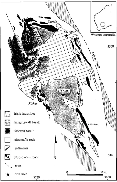
Core from two drill holes in the Kambalda Granodiorite was made available by Western Mining Corporation - Kambalda Nickel Operations. These holes were drilled during 1986 as part of the ongoing Kambalda Nickel Operations .exploration and mining development. The location of the holes is shown in Fignre 2.2. The first hole, KD 5027 was selected as a sample of the Kambalda Granodiorite within the surficial weathering zone, and penetrates to 220 m depth. The second hole, KD 6003 intersects approximately 200 m of overlying footwall basalt before penetrating the Kambalda Granodiorite to 1260 m depth. Logs of the cores are given in Appendix 2 B.
53401
REGIONAL GEOLOGY 2:5
~
- - Cainozoic CoverI
l
"
,'./
,.,
1<--"O
-7-... ~ 1l,S
j,\>~/ ,1\>/
,\,,~)Y
Cape TourviLle.
D
/ \ /,
•
D
[j
~
Jurassic dolerite
I
Penman sediments
I
[ granite! Devonian'
, granodiorite
Siluro-Devonian sediments
a
.~,~\>
c,f.' c,\'?
;/'
~~~
5330.... maficdyke
,
,
'- road/track
*
drill hole. [image:33.595.65.547.124.651.2]5320 0 600 5km Cape Degerando 610
REGIONAL GEOLOGY 2:6
\ \
\
\\
Western Australia
\
\'i:
5500
~
~\\
\
v\
Vi'
f\
fb\
0
felsic encrusiyesD
hangingwall basaltIII
footwall basaltD
ultramafic rock[Zj
sediments~
Ni ore occurrence 5440"
-
fault,,'
" " "
*
drill hole3720
o
" 2krn [image:34.595.104.488.90.687.2]3760
REGIONAL GEOLOGY 2:7
r'-'-'-._._'.-.,
I
0 ,
r'
,i
"
xI
/.,. G'
x,
30°x x x
x x x
x x
x x x
x x x x
~ x x x x x
x x x x x
~{ x
=r
x x
,jl\: v v
(jr> x x
-
.. v vv
x x
xx~
V VX X X X X
X X v v
~
:
:
v v v vv v v
x x
x x x x x x x x x x x
x x x x x x x x x x x
x x x x x x x x x x x x x x x x x x x x x x x x x x x x x x x x
x x x x x x x x
x x x x x x x x
x x x x x
x x x x
o
100kJni
""_ fault
*
drill hole Adelaidean~ Stuart Shelf sedimems Gawler Range Volcanics
•
~ Adelaide Geosynclineo
n
Archaean Gawler Cramcu
[image:35.595.92.509.89.695.2]sediments 1350 137°
REGIONAL GEOLOGY 2:8
Stuan Shelf Sequence (Roberts and Hudson, 1983), and -190 m of granitic breccia with variable alteration and mineralisation before passing into the highly altered alkali-feldspar granite basement. Appendix 2 C gives a detailed log of the core.
Representative samples of each pluton were taken on average every 100 m throughout the core, with the nominated depths given to each sample being the down-hole depths. Specific sites of alteration and veining in all three plutons, and of brecciation in the Roxby Downs Granite were noted and sampled separately. For each granite, polished thin sections, polished discs 10 = diameter by 2 = thick and powdered samples for major and isotopic analyses were produced.
The mineralogy of the three granites was initially determined using optical microscopy. Further identification was undertaken through elemental analyses of individual minerals (both quantitative for silicate minerals and qualitative for secondary and non-silicate minerals), using a JEOL JX 50A Scanning Electron Microscope (SEM) and microprobe attachment with a Tracor Northern TR-2000 Energy Dispersive Spectrometer in the Central Science Laboratory of the University of Tasmania. As a result of the non-silicate nature of many of the alteration minerals, analyses for these phases were used only as an indication of composition.
Whole rock samples were powdered to <250 Ilm for major element analysis in a tungsten-carbide centrifugal Tema swing-mill to minimise contamination during the crushing process. Major elements concentrations were determined by X-Ray fluorescence spectrometry on duplicate glass discs using a Phillips PW1410 X-ray spectrometer following the procedures reco=ended in Norrish and Chappell (1977). Samples were run against the University of Tasmania internal composite standard TasGran. Data reduction was performed on a PC-based system and errors (20') based on counting statistics were consistently < 1%. Loss on ignition was determined by weight loss from a powdered sample after heating at 1000°C for 12 hours.
REGIONAL GEOLOGY 2:9
using a Zr-constant reference frame and the gain or loss of elements relative to the freshest sample in each granite has been determined using the approach outlined by Nesbitt (1979). The procedure for mass balance calculation is given in Appendix ID, and the values for the relative percentage changes in the major and trace elements for all samples are presented in Appendix 2E.
2.3 Cotes Bay Granite
2.3.1 Field Relationships
The Coles Bay Granite pluton is located on the east coast of Tasmania (Figure 2.1). It is one of the smaller plutons that forms part of the mid-Palaeozoic granitoid suite extending southward from the Blue Tier, Scottsdale and Eddystone Batholiths in north-east Tasmania (MCOenaghan, 1989). It is intruded into early Ordovician to early Devonian sedimentary rocks and forms narrow contact metamorphic aureoles to sandstone and mudstone members of the Mathinna Beds which have been deformed by several movements of the Tabberabbean Orogeny (Cocker, 1977). Emplacement is considered to have been post-kinematic and passive (non-deformational) (McOenaghan, 1989), and the pluton displays textural features which are attributable to relatively shallow emplacement (Gee and Groves, 1971).
REGIONAL GEOLOGY 2:10
indicating that the hydrothermal fluids originated below the present exposure level (Cocker, 1977). Compositionally, the granites display high Si, high K and initial 87Sr/86Sr ratios of 0.7070
±
0.0005 (Cocker, 1982), which overlap the range for the I-type granodiorites. However, on the basis of their mineralogy and composition, these rocks have been recognised as S-type granitoids which were generated by partial melting of pelitic crusta! rocks of upper Proterozoic age (Cocker, 1977).K-Ar dating of the red Coles Bay Granite by McDougall and Leggo (1965), defmes an emplacement age ranging from 354 to 360 Ma; Rb-Sr dating of biotites from the same granite (with an initial 87SrfS6Sr = 0.705) gives an age of 375 Ma and 360 Ma for whole rock samples. Further Rb-Sr dating of biotite and whole rock samples by Cocker (1977, 1982), indicates a range of ages for the composite Coles Bay pluton with open system Sr behaviour prevailing over a narrow time interval between intrusion and alteration (Cocker, 1982). The granodiorite appears to be the oldest intrusive with ages ranging from 373 to 380.9 Ma, and is followed by intrusion of granite between 363 and 371 Ma. This age relationship is supported by the field evidence of emplacement history (Gee and Groves, 1971) with the age decreasing from east to west in the piuton (Cocker, 1977).
2.3.2 Petrography
Samples of the Coles Bay Granite were selected from the fully-cored 1008 metre deep vertical hole which passes through both grey and red members of the composite biotite granite piuton defined by Cocker (1977), however no granodiorite was intersected. A log of the hole is given in Appendix 2A.
REGIONAL GEOLOGY 2:11
Plate 2.1 Composition of the Coles Bay Granite as seen in thin section using a
transmitted light optical microscope. xlOO magnification. Q = quartz, F :: feldspar, B
:: biotite and A = accessory minerals including monazite, zircon and ilmenite.
Plate 2.2 The development of microfractures infilled with sericite, siderite and Fe-oxides in the Coles Bay Granite. Transmitted plain polarised light, xlOO
REGIONAL GEOLOGY 2:12
Accessory minerals include apatite, monazite, zircon (and isostructural xenotime), ilmenite, rutile, rare fluorite and unidentifiable sub-microscopic U{Th-rich minerals.
This porphyritic member grades both laterally and with depth into a coarse grained equigranular granite of similar mineralogy. The fine-grained microgranite is also mineralogically consistent with the coarser varieties. The variation in colour between grey, cream, pink and brick-red does not correspond to any change in primary mineralogy, rather itreflects the degree of hydrothermal alteration.
The K-feldspars are perthitic orthoclase (see K-feldspar analyses 21 - 869, Table 2.1) and contain minute fluid inclusions which produce a cloudiness in thin section. The colour of K-feldspar changes from pale pink to brick-red with increasing
alteration, which has also been attributed by Cocker (1977) to the increase in density of fluid inclusions. Albitic plagioclase (plagioclase analyses 21 - 869, Table 2.1) generally occurs in the groundmass and displays distinctive zoning and some perthitic development, as a result of exsolution. Pleochroic red-brown biotite forms ragged subhedrallaths which are commonly altered along margins and cleavage planes to chlorite, sericite and in the most severe cases, very finely-divided Ti-oxides.
Hydrothermal alteration of the granite is reflected in an increase in the proportion ofprirnary alteration minerals, particularly chlorite (see Table 2.1), sericite and Ti-oxides, and by the development of microfractures as can be seen in Plate 2.2. Sericite partially replaces both feldspars and biotite in all varieties of the granite, and may be Fe-rich in composition (Table 2.2). Definition of the Ti-oxides is difficult due to their fine-grained nature, but rutile (including brookite) and its low temperature polymorph anatase as well as some 'secondary sphene' have been detected (Table 2.2).
K-feldspar Plagioclase Biotite Chlorite
Sample No. 21 650 869 21 669 869 119 270 869 963 21 423 650 963
SiOz 64.91 65.00 65.52 67.24 68.97 66.47 35.84 34.53 34.78 35.81 32.51 23.44 29.77 24.24
Ti02 2.70 3.24 3.14 2.39
A1203 FeO(total) MnO MgO CaO 18.50 0.28 18.49 0.23 18.61 0.26 20.43 1.09 19.81 0.15 20.00 29.31 0.24 4.01 0.71 16.18 30.35 0.36 3.90 14.63 27.89 0.39 1.84 0.15 18.38 25.96 0.31 3.07 19.44 26.68 0.24 1.51 0.19 28.77 43.04 1.11 4.32 20.68 32.15 0.55 1.64 24.28 41.17 0.57 3.86
21.38 I
I
I
I
I :., t'l ClCl
~
Cl t'l 0 t'" 0 Cl...
K20 15.50 15.52 15.01 0.32 0.14 0.14 8.65 8.74 9.21 9.31 0.32 1.83
Na20 0.51 0.41 0.87 10.21 11.22 10.85 0.38
TOlal 99.70 100.59 100.28 99.28 100.29 98.18 97.31 95.90 95.64 96.48 90.04 89.84 92.90 91.22
Table 2.1 Representative analyses offe/dspars, biotite and ch/orite, Cotes Bay Granite.
'"
>..:.
Sericite Siderite* Ti-oxides Fracture-infilling phases
Sample No. 119 423 650 21 270 669 270 423 963 119 423 650a 650b
Si02 50.99 50.64 48.45 2.82 2.96 2.21 0.20 0.33 41.58 45.36 25.29 24.69
Ti02 94.85 95.67 92.42 92.42
A1203 32.65 30.75 28.92 2.39 2.16 1.81 35.00 36.47 22.81 22.12
FeO(total) 2.25 3.75 7.09 56.44 49.08 51.91 0.29 0.36 1.91 0.67 4.16 36.57 37.32
MnO 1.72 0.96 2.50 0.62 0.50 I
t'l
"
c:lMgO 0.93 0.41 1.12 2.52 3.25 0.68 0.69 0.57 2.44 2.13
I
....
0CaO 0.26 0.15 1.27 0.99 1.64 1.47 0.57
I
~
c:l t'l
KzO 8.04 10.24 9.71 0.47 2.62 0.87 0.36 0.48
I
0I
0
t-
c:l
NazO 0.40 0.28 ~
PZOj 0.23 0.29
Total 95.34 95.78 95.45 67.16 60.26 60.75 95.14 96.23 96.13 81.13 88.02 88.08 87.24
• ~remaining percentage of total present as C03.
Table
22
Representative analyses of the secondary minerals sericite, siderite, ri-oxides and thefracture-infilling phases, Coles Bay Granite.REGIONAL GEOLOGY 2:15
The clays are too fine-grained to be analysed, but previous work (D.C. Green, unpublished data) suggests that they may be illitic in composition. The secondary mineralogy of the microfractures, their association with the microgranite and the increase in intensity of hydrothermal alteration in proximity to both features suggests that they may be a product of the hydrothermal alteration process.
2.3.3 Whole Rock Geochemistry
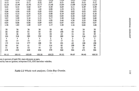
Major and trace element analyses of samples from varying depths of the Coles Bay Granite core are presented in Table 2.3. The Si- and K-rich granite displays limited compositional variation in major element geochemistry with depth or between the different members of the pluton (grey, cream, pink or microgranite). However, varying degrees of hydrothermal alteration are reflected in the mobilisation of both major and trace elements.
Mass balance calculations using a Zr-constant reference frame (see Appendix 2D and 2E) indicate that the concentrations of the more mobile major elements NaZO,
KZO, MuO and sometimes CaO generally increase with increasing degree of
alteration. This reflects the alteration mineralogy and is best demonstrated by the more severely altered and fractured samples CB 423 and CB 669 in the plot of the percent change in elemental concentrations for each sample relative to the freshest sample CB 963 (Figure 2.4). SiOZ and Alz03 also exhibit a significant increase for these samples, and a slight depletion in TiOz and PzOS in CB 669 is also observed.
CB 21 CB 119 CB 235 CB 270 CB 423 CB 650 CB 669 CB 869 CB 963 Si02 Ti02 Al203 Fe203 FeO MnO MgO CaO Na20 K20 n05 LO!* 74.61 0.13 12.35 0.61 1.44 0.06 0.20 0.58 2.87 4.89 0.05 1.36 74.52 0.14 12.49 0.34 1.53 0.06 0.15 0.81 2.99 5.19 0.06 1.82 73.88 0.17 12.92 0.60 1.08 0.02 0.16 0.97 3.10 5.36 0.06 1.68 73.67 0.22 12.77 0.57 1.62 0.05 0.25 1.12 2.13 5.52 0.09 2.57 76.48 0.07 12.48 0.38 0.90 0.05 0.08 0.62 3.17 4.82 0.01 1.17 74.04 0.21 12.84 0.49 1.53 0.04 0.19 0.85 2.50 5.46 0.07 1.30 76.45 0.02 13.09 0.11 0.72 0.02 0.05 0.50 3.24 4.30 0.01 1.16 75.63 0.11 12.30 0.39 1.35 0.03 0.12 0.69 2.86 5.23 0.05 0.64 75.37 0.17 12.29 0.38 1.53 0.03 0.16 0.83 2.80 5.06 0.07 1.66 ~ t'J
!2
Cl~
La Ce Nd Ba Se Nb Zr y Sr Rh 28 66 28 120 4 16 139 86 31 478 26 60 26 218 4 14 116 64 36 435 36 81 35 289 5 14 177 61 53 448 36 84 35 239 4 17 188 77 44 456 26 63 28 28 2 17 95 114 13 579 46 100 45 289 6 17 191 85 62. 500 19 45 21 24 3 21 62 109 14 594 24 55 24 126 5 15 120 94 33 471 38 86 39 213 3 16 158 99 50 394f:l
12
Cl <;') ."TOla' 99.15 100.10 100.00 100.58 100.23 99.52 99.67 99.40 100.35
major elements in percent of total (%), trace elements as ppm.
* = determined by Joss on ignition, comprises C02, H20 and other volatiles.
Table 23 Whole rock analyses, Coles Bay Granite.
'"
;.:. [image:44.595.108.648.102.422.2]REGIONAL GEOLOGY 2:17
200 I 0
[] [] I ~ ~ ~
'"
O<l
i
[]
•
c
..
.c
...
-
c'"
...
...
'"
'"
'"
.~
-
..
..
...
100
0
i
xi
[] [] x•
0 0•
x []•
0 [] X ~ x [] x 0•
MnO CaO Na20 K20I I 1 I I I ! I I
-100 I
....
..,
'0 <:> <:>
..,
...
....
....
'"
..,
...
t-...
...,
'0...,
...,
'"
...,
'"
...,
00
...
....
'"
Sample Depth (m)
Figure 2.4 The percentage change in selected major elements a) SW2, Ti02, A120] and P20j and b) MnO, CaO, Na20 and K20 relative to Zr at varying deprhs of the
REGIONAL GEOLOGY 2:/8 300 + ~ li' ~
'"
""
c os....
200 I + 0•
le I I c le Ba Se"
-
il
100"
...
'"
0.'"
.!: -le + 0 le + c 0 le c le•
0 le le le +•
I II
0 Nb
•
y+ Rb os
<l
...
0c
•
0• •
0
•
c-100 '
....
,
a! Vl,
0:> ! c ! t'),
0:> c ! a-I a,
t ' )
....
....
....
t ' )....
....
....
....
....
Vl\0 \0 \0 \0 00 \0
a-Sample Depth (m)
Figure 2.5 The percentage change in selected trace elements relative to Zr at varying depths of the Coles Bay Granite. Thefreshest sample which is taken as the parent is
CB 963.
2.4 Kamhalda Granodiorite2
2.4.1 Field Relationships
The Kambalda Granodiorite is a dome-like piu ton which intrudes Archaean greenstone stratigraphy in the Eastern Goldfields Province of the Yilgarn Block of West Australia (Figure 2.2) (Archibald et al., 1978). It occupies part of the fault bounded, NNW trending Kambalda dome (Gemuts and Theron, 1975) and forms contact metamorphic aureoles to the surrounding mafic-ultramafic country rocks. Two main types of intrusives have been distinguished in the Yilgarn Block by a number of workers - synkinematic and postkinematic plutons (Gemuts and Theron, 1975;
REGIONAL GEOLOGY 2:19
Archibald et al., 1978; Gresham and Loftus-Hills, 1981), which correspond to the internal and external granites of Campbell and Hill (1988).
Synkinematic granitoids are the oldest, dome-like intrusives which display well-preserved igneous textures and very little compositional variation from biotite granodiorite to adarnellite (Archibald et al, 1978). They are generally polydiapiric and occur in dynamic metamorphic terrains principally as discordant stocks within greenstone belts (Gemuts and Theron, 1975).
The younger postkinematic granitoids are geochemically indistinguishable from synkinematic bodies and they generally occur as batholiths with cross-cutting relationships to greenstone belts over a wide area (Gemuts and Theron, 1975). They appear to represent re-working of the pre-greenstone sialic basement (Campbell and Hill, 1988). Field evidence also indicates a fractionated leuco-adamellite member and gradation to synkinematic p1utons.
The Kambalda Granodiorite displays little compositional variation or evidence of diapirism and it may be regarded as part of the synkinematic granitoid group. It differs from most other intrusives of the region in that it is more highly sodic and appears to be related to felsic volcanism rather than intrusive emplacement (Gresham and Loftus-Hills, 1981). Plate 2.3 shows the textural features of the Kambalda Granodiorite.
The relationship of the two intrusive groups to structural and metamorphic activity is complex (Gresham and Loftus-Hills, 1981). Dating by Rb-Sr and Pb-Pb methods gives a range of ages for intrusive activity, varying from 2850
±
90 Ma (Ross and Hopkins, 1975) to 2610 Ma (Campbell and Hill, 1988). Pb-Pb dating of zircons from xenocrysts in the core of the Kambalda dome indicates an age of 27 60±
REGIONAL GEOLOGY 2:20
Long et aI., 1988), apparently occurring during a 100 Ma thermal anomaly period involving anatexis and crustal reworking (Archibald et al., 1978). It concluded with a K-metasomatic event and batholithic development of the postkinematic granitoids (Campbell and Hill, 1988).
2.4.2 Petrography
Sixteen diamond drill core samples of the Kambalda Granodiorite were taken from two drill holes ranging from near surface (32 metres) to 1260 metres depth. In KD 5027, samples from between 32 and 202 metres were collected and in KD 6003, samples range between 199 and 1246 metres depth. In KD 6003 the granodiorite is overlain by 190 metres of footwall basalt which crops out at the surface.
The granodiorite is massive, light grey in colour, equigranular, fine-grained and homogeneous at all depths. It comprises anhedral quartz, plagioclase and biotite laths 1 to 3 mm in diameter with lesser muscovite, plagioclase and K-feldspar (see Plate 2.3). Zoned, euhedral plagioclase is predominantly albite (plagioclase analyses 32 - 1067, Table 2.4), with a Ca:Na:K average ratio of 8.3:87.7:4.0. Calcium increases towards the margins (Ca:Na:K average =' 20.5:74.4:7.1) and with increasing
degree of saussuritisation of whole grains. K-feldspar is microcline and biotite is Mg rich (see Table 2.4). Zircon and apatite are the dominant accessory minerals with sphene, pyrite, Ti-rich magnetite and ilmenite also present. Late-stage, euhedral, zoned epidote displays increasing Fe and decreasing Ca contents from core to rim, and allanite is subordinate.
REGIONAL GEOLOGY 2:21
Plate 2.3 Composition and textural features of the Kambalda Granodiorite viewed in
thin section under transmitted plain polarised light. x 100 magnification. Q
=
quartz, FMicrocline Plagioclase Biotite Chlorite
Sample No. 98 283 885 32 607 1067 98 199 424 706 885 1139 283 424
Si02 64.74 65.4 65.10 63.79 64.01 66.47 40.52 39.30 38.57 37.93 38.38 39.00 30.39 27.13
Ti02
Al203
0.69
18.33 18.50
0.69
15.64 22.39 23.67 21.91
1.62 15.05 1.88 17.45 2.14 17.04 2.07 16.22 1.99 16.11 1.09
18.74 22.36 23.16
I
I
:" t'l~
FeO(total) MnO MgOCao
0.170.18
3.38 4.39 2.41
12.69 16.21 16.54 13.22 18.45 12.42 18.26 12.12 0.22 17.28 12.76 15.49 12.72 0.40 20.14 0.28 21.61 23.53 0.33 17.83
I
I
I
~
t;) t'lg
Cl t;)'"
K20 16.24 16.32 15.57 0.18 0.17 0.09 10.02 10.03 9.93 9.60 9.70 9.24
Na20 0.38 9.41 8.71 9.63 0.27
Total 100.00 100.23 100.54 99.33 100.95 100.51 96.11 98.43 98.55 96.42 96.22 96.68 95.04 91.98
Table 2.4
Representative analyses offeldspars, biotite and chlorite, Kambalda Granodiorite.
N
'"
Sphene Ti-oxides Epidote Sericite
Sample No. 283 424" 776 1067 32 98 162 201 32 162" 607 885 424 971
Si02 30.86 35.12 29.87 34.53 0.18 0.26 0.21 0.38 40.32 37.34 38.41 42.13 51.72 49.08
Ti02 36.94 19.47 34.82 26.16 95.43 97.44 93.32 94.74 0.20
Al203 1.22 10.04 1.01 6.72 0.44 0.19 24.67 19.72 22.64 24.30 24.11 29.35
Cr203
FeO(total) 0.61 7.66
0.18
1.98 5.08
0.25
0.83
0.31
0.67 0.81 0.67 12.40 13.02 13.17 10.77 5.41 5.09
I
I
~ t'l~
MnO MgOCao
29.772.21
15.76 28.44
2.31
21.63 0.16 1.52 0.95
0.36 0.40 21.84 0.21 20.44 0.22
23.07 21.22
0.97
0.87
1.57
I
~
Cl t'l ~ Cl Cl '<:
K20 1.88 1.93 9.67 10.93
Na20 1.55 5.02
P20S 0.23
Total 99.40 96.90 96.41 98.35 96.85 99.11 96.08 96.94 100.00 90.72 97.50 99.97 97.99 96.02
" ~severely altered grains which exhibit partial or complete replacement by Ti02.
Table
2.5Representative analyses of sphene, epidote, Ti-oxides and sericite, Kambalda Granodiorite.
N N
REGIONAL GEOLOGY 2:24
leucoxene (which comprises undistinguished finely-divided rutile, brookite and the low-temperature polymorph anatase) (Table 2.5).
Low temperature alteration is also indicated at all depths by the widespread development of secondary sulphates and carbonates including baryte, gypsum, calcite and dolomite together with kaolinite. These minerals are associated with localised, sporadic microfractures, shear zones and quartz veins and appear to be the result of recent weathering in and around the joints and fractures. Hematite, goethite and amorphous Fe-oxides and hydroxides are more restricted in occurrence and are found replacing secondary epidote and sphene, suggesting that post-emplacement alteration has been limited to mobilisation of low-temperature sulphate and carbonate fluids. Intense fracturing of the granodiorite is not abundantly evident, with only small and sporadic stringers and veins of the carbonate and sulphate minerals throughout the pluton.
2.4.3 Whole Rock Geochemistry
Whole rock major and trace element analyses for the Kambalda Granodiorite are presented in Table 2.6. With the exception of the sampie at 283 m, the granodiorite is homogeneous throughout all depths, displaying consistent Si02, A1203, total Fe and K20 and an enrichment in Na20 (up to 6%) and Ti02 (up to 0.25%). MgO values vary around I % in surface samples to 464 m depth, and are then reduced to 0.5% with increasing depth. The near-surface samples display a high loss on ignition (H20 and COz) content and increase in FeIII content reflecting the higher degree of alteration at this depth.
Mass balance calculations for the major and trace elements using a Zr-constant reference frame and KD 1246 as a parent composition are given in Appendix 2 E. They also indicate this variation in intensity of alteration, as shown in Figures 2.6 and
KD32 KD98 KD 162 KD199 KD201 KD283 KD368 KD464
Si02 70.70 70.24 71.25 71.83 70.24 68.92 71.87 72.16
Ti02 0.25 0.23 0.23 0.20 0.22 0.24 0.25 0.22
A1203 15.37 14.85 14.71 15.18 14.67 13.93 14.98 15.26
Fc203 0.57 0.59 0.57 0.57 0.51 0.75 0.50 0.45
FeO 0.90 1.08 0.99 0.81 0.99 1.98 0.99 0.99
MnO 0.02 0.02 0.Q2 0.02 0.02 0.04 0.Q2 0.Q2
MgO 1.04 0.96 1.00 0.57 0.90 2.64 0.91 0.65
CaO 1.28 1.80 1.92 2.02 1.90 2.74 1.85 2.07
Na20 5.54 5.81 5.73 5.63 5.76 5.03 5.63 5.52
K20 2.68 2.66 2.62 2.35 2.63 2.42 2.37 2.39
n05 0.08 0.10 0.11 0.08 0.09 0.09 0.09 0.09 t>1
'"
La1' 1.21 1.09 1.08 0.47 1.53 0.69 0.78 0.68
~
La 21 26 24 22 21 20 24 17
Cc 43 47 45 40 38 35 41 38
~
Nd 16 19 15 14 13 12 13 11 Cl
Ba 1022 1137 1030 1162 1238 1000 1222 1266 t>1
g
Se 2 3 3 2 3 7 2 3
Nb 3 3 3 3 3 3 3 2 Cl Cl
Zr 114 113 113 106 113 98 113 108
...,
Y 3 5 4 4 3 6 3 4
Sf 731 791 802 801 787 687 778 820
Rb 70 75 67 66 69 89 73 64
Total 99.64 99.43 100.23 99.73 99.46 99.47 100.27 100.50 major elements inpcrccnt of total (%), trace elements as ppm.
... -::; (lclt~TlT1ined by I{)s~on i!~nilion,comprises C02, H20 IInd olher volnLilcs.
Table 2.6 Whole rock analyses, Kambalda Granodiorite.
N
[image:53.595.167.612.112.398.2]KD607 KD706 KD776 KD885 KD971 KD 1067 KD 1139 KD 1246
Si02 72.11 72.60 70.64 71.21 71.21 71.67 71.12 71.97
Ti02 0.23 0.19 0.20 0.22 0.20 0.21 0.26 0.23
A1203 15.34 14.80 15.20 15.33 14.79 14.91 15.41 15.59
Fe203 0.37 0.53 0.45 0.37 0.44 0.39 0.55 0.40
FeO 0.99 0.81 0.99 0.99 0.81 0.99 0.99 0.99
MnO 0.02 0.02 0.02 0.02 0.01 0.01 0.02 0.02
MgO 0.58 0.48 0.64 0.68 0.52 0.55 0.86 0.61
CaO 2.15 1.88 2.20 2.15 1.94 2.10 2.23 2.30
Na20 5.53 5.68 5.85 6.13 5.65 5.77 5.99 5.81
K20 2.32 2.78 2.36 2.38 2.71 2.51 2.35 2.24
P205 0.07 0.07 0.09 0.09 0.07 0.09 0.10 0.08
'"
LO!* 0.49 0.96 0.81 0.91 1.15 0.59 0.46 0.35
'"
~
La 22 19 21 19 18 18 17 20
Cc 35 35 36 38 33 31 33 38
~
Nd 13 14 11 14 12 10 13 28 C"l
Ba 1123 1332 1360 1215 1546 1278 1221 1150
Se 3 2 3 3 3 2 3 3 ~
'"
Cl
C"l
Nb 2 3 2 2 2 3 2 3
Zr 108 98 102 109 98 106 116 112
Y 4 4 3 5 3 5 3 5
"""
Sr 834 771 818 858 789 783 905 879
Rb 66 77 69 68 75 76 65 64
Total 100.20 100.80 99.45 100.49 99.50 99.79 100.33 100.59
major elements inpcrcent of total (%), trace elements as ppm.
* = determined by loss on ignition, comprises C02, H20 and other volntlles.
Table 2.6 Whole rock analyses, Kambalda Granodiorite.
N N