Efficient test compaction for combinational circuits
based on Fault detection count-directed clustering
A. El-Maleh and S. Khursheed
Abstract:Test compaction is an effective technique for reducing test data volume and test appli-cation time. The authors present a new static test compaction technique based on test vector decomposition and clustering. Test vectors are decomposed and clustered for faults in an increasing order of faults detection count. This clustering order gives more degree of freedom and results in better compaction. Experimental results demonstrate the effectiveness of the proposed approach in achieving higher compaction in a much more efficient CPU time than the previous clustering-based test compaction approaches.
1 Introduction
Recent advances in very large scale integration (VLSI) tech-nology have enabled the fabrication of systems-on-a-chip with millions of transistors. This tremendous increase in tran-sistor count has resulted in large increase in test data volume that often exceeds current testers’ memory capacity. In order to reduce the test data volume, two basic strategies have been investigated. The first strategy is based on reducing the required number of test vectors needed to achieve a given desired fault coverage, known as test compaction. The second strategy is based on representing the test data in a compressed form in the tester and using decompression cir-cuitry on chip to decompress the test data before application, known as test compression. Both strategies are necessary to reduce test data volume and test application time.
Test compaction techniques can be classified asstaticor dynamic. In static test compaction, the number of test vectors is reduced after they are generated, whereas in dynamic test compaction, the number of test vectors is mini-mised during the automatic test pattern generation (ATPG) process. Static test compaction algorithms for combina-tional circuits can be divided into three broad categories [1]: (1) redundant vector elimination, (2) test vector modifi-cation; and (3) test vector addition and removal. In the first category, compaction is performed by dropping redundant test vectors. A redundant test vector is a vector whose faults are all detectable by other test vectors. Static compac-tion algorithms falling under this category are either based on set covering [2 – 4] or test vector reordering and fault simulation [5 – 9]. In the second category, compaction is performed by modifying test vectors. This is achieved by merging of compatible test vectors based on test relaxation or raising [10 – 13], essential fault pruning [7, 13 – 15], or test vector decomposition and clustering [1, 16, 17].
Finally, the third category of static compaction algorithms consists of compaction algorithms that add new test vectors to a given test set in order to remove some of the already existing test vectors[8, 18].
Static compaction techniques are preferred to dynamic compaction for several reasons. First, generating compact test sets using dynamic compaction is more time-consuming as many attempts to modify partially specified test vectors to detect additional faults often fail [12]. In addition, dynamic compaction does not take advantage of random test generation that makes the ATPG process more efficient. Second, static compaction is ATPG-independent allowing test sets to be generated using more efficient ATPG tech-niques. Finally, static compaction techniques could result in more compact test sets than dynamic compaction tech-niques as indicated by the results in[9, 15].
Recently, two static compaction techniques based on test vector decomposition and clustering have been proposed in
[1, 16, 17]. The first technique, called independent fault clus-tering (IFC) [1, 16], is based on clustering test vectors according to independent fault sets. The second technique, called class-based clustering (CBC)[1, 17], is based on clas-sifying test vectors into classes and then eliminating test vectors by moving their components to other test vectors.
In this work, we propose a new test compaction technique based on test vector decomposition and clustering. Test vector decomposition and clustering is performed for faults based on the number of test vectors detecting each fault, that is fault detection count. This is in contrast to IFC which clusters test vectors based on independent fault sets.
2 Proposed test compaction technique
Test vector decomposition is the process of decomposing a test vector into its atomic components. An atomic com-ponent is a child test vector that is generated by relaxing its parent test vector for a single fault f. That is, the child test vector contains only the assignments necessary for the detection of f. Besides, the child test vector may detect other faults in addition tof.
In IFC[1, 16], independent fault sets (IFSs) with respect to a given test set are first derived. Two faults are independent if they are not detected by the same test vector. Then, test vector clustering is performed based on the derived IFSs. This is motivated by the fact that the size of the largest IFS
#The Institution of Engineering and Technology 2007 doi:10.1049/iet-cdt:20070004
Paper first received 6th January 2006 and in revised form 6th February 2007 A. El-Maleh is with the Department of Computer Engineering, King Fahd University of Petroleum and Minerals, P.O. Box 1063, Dhahran 31261, Saudi Arabia
S. Khursheed is with the Department of Electronics and Computer Science, University of Southampton
gives an upper bound on the possible size of the final test set after compaction and that test vector components for faults belonging to different IFSs are potentially compatible. During test vector clustering, compatible components, corre-sponding to compatible faults, are mapped to the same com-patibility set. Whenever a component is mapped to a compatibility set, it is merged with the partial test vector of that compatibility set. At the end of the clustering process, each compatibility set represents a single test vector.
Our proposed test compaction technique, fault-detection count-based clustering (FCC), is based on clustering test vector components based on fault-detection count. Components derived from faults with the smallest detection count are clustered first followed by faults with increasing detection count. This is motivated by the fact that faults with Ndetection count haveNtest vector components and have a higher chance of being compatible with the existing clusters. If a test vector component is not compatible with all the exist-ing clusters, other test vector components are attempted. A new cluster is created only when all theNtest vector com-ponents are not compatible with all the existing clusters.
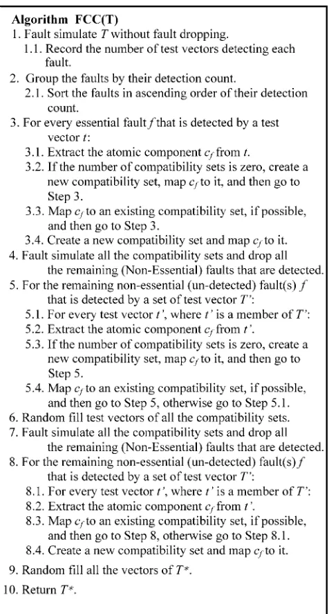
The FCC algorithm is shown inFig. 1and proceeds as follows. First, the given test set T is fault-simulated without fault dropping. This step is performed to find the
number and set of test vectors that detect every fault. Second, all the faults are sorted using their detection count in ascending order. Next, test vector components for essential faults (i.e. detection count¼1) are clustered. In this step, for every essential fault f detected by t, the atomic component cf corresponding to f is extracted from
t. Then, for every compatibility setCSi, if cfis compatible with the partial test vector in CSi, cf is mapped to CSi. On the other hand, if the number of compatibility sets is zero or cf is incompatible with all partial test vectors in the existing compatibility sets, a new compatibility set is created andcfis mapped to it.
Next, the algorithm fault simulates the existing compat-ibility sets and drops all detected faults. This step saves the computation time which is otherwise spent on extracting atomic components of yet unmapped, non-essential faults and then either mapping them to the existing compatibility sets or creating a new compatibility set for such faults. In addition, it could result in higher compaction.
The algorithm then focuses on the remaining unmapped, non-essential faults. This step exhaustively checks every component of a non-essential fault and attempts to minimise creating a new compatibility set. For every fault, an atomic component of a faultfis extracted. If it is incompatible with all partial test vectors in the existing compatibility sets, a new component is tried. In this step, a new compatibility set is created only if the number of compatibility sets is zero, which is possible only when there are no essential faults. At this point, only those non-essential faults remain which require a new compatibility set and none of their atomic component could be mapped to any of the partially filled existing compatibility sets.
The algorithm then randomly fills the partially filled test vectors of the existing compatibility sets and fault-simulates all the compatibility sets. This is done to maximise the chances of detecting yet unmapped, non-essential faults and therefore save an extra compatibility set. It should be noted that random filling in step 6 does not affect compac-tion, since it is guaranteed that none of the remaining test vector components could map to any of the existing par-tially filled test vectors.
Finally, the unmapped remaining non-essential faults are clustered. The algorithm creates an additional compatibility set for the remaining non-essential faults only if all com-ponents of a fault f are incompatible with all partial test vectors in the existing compatibility sets. It should be noted that at this stage compatibility is only checked with newly created clusters. At the end, the algorithm randomly fills the remaining partially filled test vectors and returns the compatibility sets as the compacted test set.
It is worth mentioning that for large circuits with large number of faults, fault-simulation without dropping can be restricted to aknumber of fault detects. The value ofk chosen provides a tradeoff in memory and CPU time requirement and the achieved level of compaction.
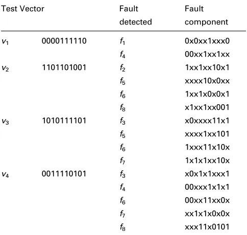
We next illustrate the steps of the proposed FCC algor-ithm through an example.Table 1shows a set of four test vectors along with their detected faults and the components generated for each fault. Faultsf1andf2are essential faults and will be clustered first resulting in two sets as shown in
Table 2. We assume in this example that fault-simulating the resulting compatibility sets will not detect additional faults. Then, faults with detection count¼2 will be clus-tered next, i.e., faultsf3,f4,f5,f7andf8. The first component off3¼x0xxxx11x1 will be attempted for clustering and it will be found incompatible with the existing sets. The second component off3¼x0x1x1xxx1 is then successfully clustered into the second set. The first component of
[image:2.595.50.288.311.754.2]f4¼00xx1xx1xx is successfully clustered into the first set. However, none of the components of the faultsf5,f7andf8 can be clustered in the existing sets and hence their cluster-ing is delayed. Next, clustercluster-ing is attempted for faults with detection count¼3, that is, f6. While neither the first nor the second components off6can be clustered into the exist-ing sets, the third component of f6¼00xx11xx0x is suc-cessfully clustered into the first set. Next, the algorithm will randomly fill the merged test vectors of the compatibil-ity sets and will fault-simulate the remaining undetected faults, that isf5,f7andf8. We assume in this example that fault f5 will be detected by the randomly filled test vectors. Finally, f7and f8will be clustered next. The first component of f7¼ 1x1x1xx10x is mapped to a new set. Then, the first component of f8¼ x1xx1xx001 is found incompatible with the third set and hence its second
com-ponent is attempted. The second component of
f8¼xxx11x0101 is then found compatible with the third set and is clustered with it creating the merged test vector 1x111x0101, which is randomly filled to create a fully specified test set. Thus, the test set is compacted into the fol-lowing three test vectors: f0001110100, 1011011001, 1111100101g.
3 Experimental results
In order to demonstrate the effectiveness of the proposed FCC test compaction technique, we have performed exper-iments on a number of the ISCAS85 and full-scanned
versions of ISCAS89 benchmark circuits. The experiments were run on a Pentium Mobile, with 2.0 GHz processor and 1GB DDR2 RAM. We have used test sets generated by HITEC[19], which achieve full coverage of all detectable faults in the circuits. HITEC test sets are used for compari-son with the work in[1, 10, 16]. In addition, we have used the fault simulator HOPE[20]for fault-simulation purposes and the test relaxation algorithm in [10] for test vector component generation.
In Table 3, we compare the test compaction results of IFC[1, 16]and FCC algorithms when applied on the orig-inal test set. The first column gives the circuit name. The second column specifies the number of test vectors in the original test set before applying any compaction. The third and fourth columns give test set sizes after applying reverse-order fault simulation (ROF) and random merging (RM) [10], respectively. ROF is based on apply-ing reverse-order and random order fault simulation for 20 iterations. RM is based on relaxing the test vectors gen-erated by ROF and merging compatible vectors. Columns five and six give the results of the IFC technique [1, 16]
while columns seven and eight report the results of the pro-posed FCC technique. Test set sizes are given under the column headed #TV. The CPU time, in seconds, required by each of the techniques is given under the column headed Time. The FCC technique has shown better com-paction quality on 12 out of 15 circuits, while two circuits resulted in a draw. In terms of overall savings, FCC has saved more than 120 test vectors than IFC [1, 16] (with an average compaction improvement of 7%). For example, for the circuits c3540 and c5315, FCC achieved 24% and 25% higher compaction than IFC, respectively. Furthermore, FCC consumes significantly lesser CPU time than IFC [1, 16]. It has shown 13.37 times overall improvement than IFC [1, 16].
In order to increase the level of compaction, FCC can be applied in an iterative manner until no compaction improve-ment is possible. We have experiimprove-mented with an iterative version of FCC, called FCC6þ, by applying FCC iteratively until the length of the test set cannot be reduced in the last six iterations. Unspecified bits in the test setTare assigned random values before every call to the FCC algorithm. Columns nine and ten in Table 3 report the results of an iterative version of IFC applied on the test set generated by ROF, called ROFþITER_IFC [1, 16]. Columns 11 and 12 report the results of FCC6þ. It can be seen that FCC6þ has achieved higher test compaction than ROFþITER_IFC on 12 out of 15 circuits, while two resulted in a draw. For example, for the circuit c5315,
FCC6þ has achieved 29% more compaction than
[image:3.595.47.289.44.274.2]ROFþITER_IFC. Furthermore, it has shown higher overall savings (with an average compaction improvement of 8%) in a much more efficient CPU time (ranging from 1 to 14 times less CPU time). It should be observed that
Table 1: Example test vectors and their components
Test Vector Fault
detected
Fault
component
v1 0000111110 f1 0x0xx1xxx0
f4 00xx1xx1xx
v2 1101101001 f2 1xx1xx10x1
f5 xxxx10x0xx
f6 1xx1x0x0x1
f8 x1xx1xx001
v3 1010111101 f3 x0xxxx11x1
f5 xxxx1xx101
f6 1xxx11x10x
f7 1x1x1xx10x
v4 0011110101 f3 x0x1x1xxx1
f4 00xxx1x1x1
f6 00xx11xx0x
f7 xx1x1x0x0x
f8 xxx11x0101
Table 2: Illustration of steps of FCC algorithm on the given example
After mapping faults with
detection count¼1
After mapping faults with
detection count¼2
After mapping faults with
detection count¼3
After merging
components
After random
filling
Cluster Fault Fault component Fault Fault component Fault Fault component Test vector Test vector
1 f1 0x0xx1xxx0 f1 0x0xx1xxx0 f1 0x0xx1xxx0 000x11x100 0001110100
f4 00xx1xx1xx f4 00xx1xx1xx
f6 00xx11xx0x
2 f2 1xx1xx10x1 f2 1xx1xx10x1 f2 1xx1xx10x1 10x1x110x1 1011011001
[image:3.595.48.553.658.774.2]FCC6þconsumes more time on s15850 at the expense of more compaction as the algorithm continued on iterating due to more compaction improvements achieved.
InTable 4, a comparison is made for the largest circuits between the number of compacted test sets obtained by FCC6þ and those obtained by Mintest [15] using both dynamic and static compaction techniques. It should be observed that Mintest static compaction has reported the smallest known test sizes for several circuits. For five out of the six compared circuits, the test size of FCC6þ is smaller than Mintest dynamic test compaction. Comparison in terms of CPU time is not made as the CPU time taken by Mintest dynamic compaction is not available. However, it is known that running ATPG with dynamic test compaction is slower than regular ATPG mode. While for all the circuits, the number of test vectors obtained by Mintest static compaction is smaller, the CPU time is significantly higher than FCC6þ, limiting the practicality of the technique for large industrial circuits.
It should be pointed out that any static compaction algor-ithm can be used after the proposed FCC algoralgor-ithm. In fact, given a test set T, the FCC algorithm will generate a new test set T whose characteristics are different from the characteristics of T. Thus, a static compaction algorithm that cannot compactTmay manage to compactT.
4 Conclusions
In this work, we have proposed a new test compaction tech-nique for combinational circuits based on test vector decomposition and clustering. Test vectors are decomposed and clustered for faults in an increasing order of fault detec-tion count. Experimental results have demonstrated the effectiveness of the proposed technique in achieving higher level of compaction in a much more efficient CPU time than previously proposed clustering-based test com-paction techniques. An iterative application of the proposed technique has also shown significant increase in the achieved level of test compaction.
5 Acknowledgment
This work is supported by King Fahd University of Petroleum and Minerals under project#FT-2004/07.
6 References
1 El-Maleh, A.H., and Osais, Y.E.: ‘Test vector decomposition based static compaction algorithms for combinational circuits’, ACM Trans. Design Automat. Electron. Syst., 2003,8, (4), pp. 430 – 459 2 Flores, P.F., Neto, H.C., and Marques-Silva, J.P.: ‘On applying set
[image:4.595.46.560.44.290.2]covering models to test set compaction’. Proc. 9th Great Lakes Symposium on VLSI, Ypsilanti, Michigan, March 1999, pp. 8 – 11
Table 3: Comparison of compaction results
Circuit Orig. #TV ROF RM[10] IFC[1, 16] FCC ROFþ
IFC-ITR[1, 16]
FCC6þ
#TV #TV #TV Time(s) #TV Time(s) #TV Time(s) #TV Time(s)
c2670 154 106 100 98 0.993 98 0.04 85 42.07 82 3.93
c3540 350 83 80 99 2.01 75 1.01 75 26.95 63 5.05
c5315 193 119 106 107 3.97 80 1.96 86 88.04 61 10.94
s13207.1f 633 476 252 244 34.06 238 10.02 238 473.12 234 69.02
s15850.1f 657 456 181 142 50.97 144 15.97 129 374.95 118 1365.98
s208.1f 78 33 33 34 0.001 32 0.001 32 0.01 32 0.01
s3271f 256 115 76 60 1.95 59 1.93 60 18.98 55 3.95
s3330f 704 277 248 238 3.05 230 0.99 196 30.02 192 4.2
s3384f 240 82 75 72 1.98 72 0.96 72 7.07 72 2.98
s38417f 1472 822 187 150 838 130 225.95 120 3775.06 108 2337
s38584f 1174 819 232 148 4718 138 154.02 124 8217.08 114 1735.17
s4863f 132 65 59 50 3.02 47 3.95 42 70.88 38 6.96
s5378f 359 252 145 120 3.05 119 1 117 109 107 13.99
s6669f 138 52 42 40 7.91 36 5.02 30 175.01 28 12.02
s9234.1f 620 375 202 182 11.06 170 3.04 155 200.93 139 27.04
Table 4: Comparison with Mintest [17] dynamic and static compaction test sets
Circuit FCC6þ Mintest
dynamic [15]
Mintest static [15]
#TV CPU time #TV #TV CPU time
s5378f 107 13.99 111 97 131.5
s9234.1f 139 27.04 159 105 3157.1
s13207.1f 234 69.02 236 233 1178.4
s15850.1f 118 1365.98 126 94 9252.1
s38417f 108 2337 99 68 28955.8
[image:4.595.84.517.335.463.2]3 Boateng, K.O., Konishi, H., and Nakata, T.: ‘A method of static compaction of test stimuli’. Proc. Asian Test Symp., Kyoto, Japan, November 2001, pp. 137 – 142
4 Hochbaum, D.S.: ‘An optimal test compression procedure for combinational circuits’,IEEE Trans. Comput. Aided Design Integr Circuits Syst., 1996,15, (10), pp. 1294– 1299
5 Schulz, M.H., Trischler, E., and Sarfert, T.M.: ‘SOCRATES: a highly efficient automatic test pattern generation system’, IEEE Trans. Comput. Aided Design Integr. Circuits Systems, 1998, 7, (1), pp. 126 – 137
6 Pomeranz, I., and Reddy, S.M.: ‘Forward-looking fault simulation for improved static compaction’, IEEE Trans. Comput. Aided Design Integr. Circuits Syst., 2001,20, (10), pp. 1262 – 1265
7 Hamzaoglu, I., and Patel, J.H.: ‘Test set compaction algorithms for combinational circuits’. Proc. Int. Conf. on Computer-Aided Design, San Jose, CA, November 1998, pp. 283 – 289
8 Kajihara, S., Pomeranz, I., Kinoshita, K., and Reddy, S.M.: ‘Cost effective generation of minimal test sets for stuck-at faults in combinational logic circuits’, IEEE Trans. Comput. Aided Design Integr. Circuits Syst., 1995,14, (12), pp. 1496 – 1504
9 Lin, X., Rajski, J., Pomeranz, I., and Reddy, S.M.: ‘On static test compaction and test pattern ordering for scan designs’. Proc. Int. Test Conf., Washington, DC, USA, 2001, pp. 1088– 1098
10 El-Maleh, A., and Al-Suwaiyan, A.: ‘An efficient test relaxation technique for combinational and full-scan sequential circuits’. Proc. of VLSI Test Symposium, Monterey, CA, 2002, pp. 53 – 59 11 Ayari, B., and Kaminska, B.: ‘A new dynamic test vector
compaction for automatic test pattern generation’, IEEE Trans. Comput. Aided Design Integr. Circuits Syst., 1994, 13, (3), pp. 353 – 358
12 Miyase, K., Kajihara, S., and Reddy, S.M.: ‘A method of static test compaction based on don’t care identification’. Proc. First IEEE Int. Workshop on Electronic Design, Test, and Application, Christchurch, New Zealand, January 2002, pp. 392 – 395
13 Chang, J.-S., and Lin, C.-S.: ‘Test set compaction for combinational circuits’,IEEE Trans Comput. Aided Design Integr. Circuits Syst., 1995,14, (11), pp. 1370 – 1378
14 Reddy, L.N., Pomeranz, I., and Reddy, S.M.: ‘ROTCO: a reverse order test compaction technique’. Proc. EURO-ASIC Conf., Paris, France, June 1992, pp. 189–194
15 Hamzaoglu, I., and Patel, J.H.: ‘Test set compaction algorithms for combinational circuits’,IEEE Trans Comput. Aided Design Integr. Circuits Syst., 2000,19, (8), pp. 957 – 963
16 Osais, Y.E., and El-Maleh, A.H.: ‘A static test compaction technique for combinational circuits based on independent fault clustering’. Proc. 10th IEEE Int. Conf. on Electronics, Circuits and Systems, Sharga, United Arab Emirates, December 2003, vol. 3, pp. 1316 – 1319 17 El-Maleh, A.H., and Osais, Y.E.: ‘A class-based clustering static compaction technique for combinational circuits’. Proc. 16th Int. Conf. on Microelectronics, Tunis, Tunisia, December 2004, pp. 522–525 18 Kajihara, S., Pomranz, I., Kinoshita, K., and Reddy, S.M.: ‘On
compacting test sets by addition and removal of test vectors’. VLSI Test Symp., Cherry Hill, USA, April 1994, pp. 25 – 28
19 Niermann, T.M., and Patel, J.H.: ‘HITEC: a test generation package for sequential circuits’. Proc. European Conf. Design Automation, Amsterdam, The Netherlands, 1991, pp. 214 – 218
![Table 4:Comparison with Mintest [17] dynamic and static compaction test sets](https://thumb-us.123doks.com/thumbv2/123dok_us/8491622.344809/4.595.46.560.44.290/table-comparison-mintest-dynamic-static-compaction-test-sets.webp)
