Rochester Institute of Technology
RIT Scholar Works
Theses
Thesis/Dissertation Collections
2002
A Demonstration in communication and task
completion between two autonomous robots
Adam Renzi
Follow this and additional works at:
http://scholarworks.rit.edu/theses
This Thesis is brought to you for free and open access by the Thesis/Dissertation Collections at RIT Scholar Works. It has been accepted for inclusion
in Theses by an authorized administrator of RIT Scholar Works. For more information, please contact
.
Recommended Citation
A Demonstration in Communication and
Task Completion Between Two
Autonomous Robots
By
Adam Domenic Renzi
A Thesis Submitted in
Partial Fulfillment of the
Requirement for the
MASTER OF SCIENCE
IN
MECHANICAL ENGINEERING
Approved by:
Dr. Wayne Walter
Department of Mechanical Engineering
Dr. Agamemnon Crassidis
Department of Mechanical Engineering
Dr. Ferat Sahin
Department of Electrical Engineering
Permission Granted
A Demonstration in Communication and Task Completion
Between Two Autonomous Robots
I, Adam Domenic Renzi, hereby grant permission to the Wallace Library of the Rochester
Institute of Technology to reproduce my thesis in whole or in part. Any reproduction will
not be for commercial use or profit.
Acknowledgements
I
would
like
to thank the
following
people
for
their
continuoushelp
on
this
project.Without
all of
you, I
would
have
never made
it
all
the
way
through.
Thanks
so
muchto:
Dr.
Wayne
Walter,
Matt
Williams,
Dr.
Raguveer
Rao,
Dave
Hathaway,
Jim
Grenier,
John
Wellin,
Dr. Mark
Kempski,
Jeff
Gagliardo,
Brian
Hirth,
andJeremiah Parry-Hill.
Finally,
thanks to
Kellie Scheurer. Without her love
and
full
supportthrough this
wholeprocess,
I
Abstract
The
world of robotics
is
rapidly
changing.
No
more are
the
days
of
robotics classesbeing
taught that
focus
merely
onhighly
industrial,
automation
robots.Today's
roboticsis
focusing
more and more on microcontrollers and
their
implementation into
everyday
life.
Miniature
robotics
and
how it is
implemented
to
make common
tasks
easieris
becoming
the
focus
of
many
robotics classes across
the
world.
Microcontrollers
allow users
to
control several
inputs
and outputs
to
complete
somewhat
difficult
tasks. In
today's society,
one
mightfind
a microcontroller
in
anything
from
a computer
to the
average
household
toaster.
As
time
has
passed,
microcontrollershave
become
more powerful with an
increased
ability
to
control moreand
moreinputs
and
outputs.
In
many
industries,
pipe
inspection is
critical
to
success.Leaks
and cracks
in
pipesand
tubes
canlead
to
multisystem
failure. Sometimes
the
pipes
canbe
impossible
to
inspect
with
the
human
eye
due
to their
length
and
location. Rather
than
use anumbilical corded
system
that
would requiremany
feet
or miles of
cable,
it is
highly
desirable
to
create awireless system
to
complete
the task
of pipe
inspection
and
repair.The
purpose of
this
project
is
to
utilizemicrocontrollers
to
control
two
robots
to
complete
the
following
tasks:
Locate
a
hole in
a random
length
of piping.
Communicate
the
hole
position
between
the two
robots.
Simulate
the
sealing
process ofthe
hole.
Through
the
completionof
the
above-mentioned
goals,
this
project
markedthe
beginning
of
the
Laboratory
of
Autonomous Cooperative Microsystems
(LACOMS)
atRochester
Institute
of
Technology.
The
final
version of
this
project will
allowfor
wireless
communication
between
two
robots,
making
the
task
doable
with no
human
interference,
and
hence,
the two
robots will
be
totally
autonomous.
Future
versions
ofthis
projectcan
then
Table
of
Contents
Section
Page
No.
I.
Table
of
Figures
8
III. Introduction
10
Problem Definition
10
1
.Umbilical Corded Robots
1 1
2. Autonomous Robots
16
3. Case Studies in
Autonomous
Robotic
Communication
20
3.01
Introduction
20
3.02
VPI Army-Ant Cooperative
Lifting
Project
20
3.03
Carnegie
Mellon Robotic Soccer
Project
25
3.04
Conclusions
30
IV.
LEGOS
Prototyping
31
1
.The
Beginning
of
LACOMS
3 1
2. Locomotion
Systems
3 1
3.
Sensory
Systems
32
4. Communication Systems
33
5.
Conclusions
34
V.
Alternative Designs
Considered
35
1
.Locomotion Systems
35
2.
Sensory
Systems
39
3. Communication
Systems
43
VI.
Final Design Details
46
1
.Locomotion
Systems
46
1.01
Chassis
46
1.02 Drive
System
51
2.
Microcontroller
Choice
54
4.03
RF
Communication Hardware
66
4.04
RF
Communication for Task Completion
67
5.
Sealant Systems
67
5.01
Top
Level
Concept
67
5.02
Pump
68
5.03
Relay
and
Darlington Transistor Connection
68
5.04
Sealant Reservoir
69
5.05
Sealant Hose
and
Nozzle
69
5.06
Light-Seeking
Array
w/
Sealant
Nozzle Hole
69
6. Component
Wiring
69
6.01
Top
Level Concept
69
6.02
BASIC
Stamp
H Microcontroller
Wiring
69
6.03
Hole-Finding
Robot (Robot
#1)
71
6.03.1 Inputs
71
6.03.2
Outputs
71
6.04
Light-Seeking
Robot
(Robot
#2)
72
6.04.1
Inputs
72
6.04.2
Outputs
72
7.
Programming
and
Logic Flow
73
7.01
Top
Level Concept
73
7.02
Hole-Finding
Robot (Robot
#1)
Logic Flow
74
7.03
Light-Seeking
Robot
(Robot
#2)
Logic Flow
75
VII.
Robot
Assembly
78
1
.Component Placement
78
1.01
Hole-Finding
Robot
(Robot
#1)
78
1.02
Light-Seeking
Robot
(Robot
#2)
79
VIII.
Testing
81
1
.Top
Level
Concept
8
1
1.01
Robot
#1
Locomotion
81
1.02
Robot
#1
Array
Rotation
81
1.03
Robot
#1
Hole-Finding
81
1.04
Switch Communication
when
Hole Found
82
1.05
Robot #2 Locomotion
82
1.06
Sonar
Sensor
Utilization
82
1.07
Robot #1 LED
Rotation
83
1.08
Robot
#2 Light
Sensor Utilization
83
1.09
Switch
Communication
when
Robot
#2
Arrives
84
1.10
Final
Hole
Position Locomotion
84
IX.
Recommendations for Future Work
87
1.
Overall Thoughts
87
1.01
Locomotion
87
1.02
Drive
System
87
1.03
Hole-Finding
Sensors
87
1.04
Communication
Method
88
1.05
Energy
Efficiency
88
1.06
Sealant System
88
X.
Conclusions
90
1.
Overall
Thoughts
90
1.01
A Robust Demonstration
90
1.02
Cost
Analysis
91
2.
Differences/Improvements
Over
Past Projects
92
3.
Final Thoughts
93
XI.
Bibliography
94
XII. Appendicies
A. Servo Motor
Modificiation
A-l
1
.Top
Level
Concept
A-
1
2.
Servo
Modification,
Step
1
A-l
3.
Servo
Modification,
Step
2
A-l
4.
Servo
Modification,
Step
3
A-2
5.
Servo
Modification,
Step
4
A-2
6. Servo
Modification,
Step
5
A-2
7.
Servo
Modification,
Step
6
A-2
B. Handbook
Information
on
Alternative
Design
Products
B-l
1
.Summary
of
Components
B-
1
C. Component Drawings
C-l
1
.Summary
of
Components
C-
1
D. Project
Components
D-l
1
.Summary
of
Components
D-
1
II.
Introduction
There
are
several mainissues
that this
project
deals
with.
At
first
glance, the
mainproblem
seems
to
be
locating
and
sealing
of a
hole
in
a pipe or
tube.
This
problem needsto
be
solved via multiple robots
that
can communicate
autonomously
with
each otherto
solveit.
In
the
area of
communication,
since
this
project
is
the
first
underthe
LACOMS
group,
wireless communication
is
highly
desirable.
A
main
goalof
the
project
is
to
be
able
to
showcommunication
between
two
or
morerobots
at
the
conclusionof
the testing.
By
using
wireless
communication,
this
project
canbe
built
upon withfuture
projectsthat
will
communicate
witheven more robots.
In
the
area oftask completion, the
goal ofhole sealing
is
one
that
required muchdesign
anddevelopment
to
complete.Throughout
this
write-up
one
will seehow
the
design
of
eachrobot and
its
componentstook
place.The
ultimategoal
is
to
utilize several
different
sensors
to
find
a
hole,
and
then
send
this
information
to
another robot.This
secondrobot
would
in
turn
use various
sensorsto
fill
the
hole
with a
specifiedsealant.
The
problems
in
this
projectare quite
uniquein
that
they
have
neverbeen
solved
before.
As
one will
be
ableto
seein
the
literature
searchportion
ofthis
report,
using
wireless
communication
to
complete
the task
of
hole sealing
is
something
not yet
done
as of
the
time
of
this
report.In
today's
society
there
are
many
roboticsprojects
that
are
on-going
or
already
developed
that
feature
multiplerobots
that
complete
atask together.
However,
there
are
hardly
any
that
use wireless communication.Those
projectsthat
do
usewireless
communication
do
not
feature
any
task
completion.
On
many
of
the
wireless projects
that
are
in
productiontoday,
the
only
goalof
the
wirelesscommunication
is
to transfer
information,
and not
to
complete a
task.
The
following
is
a
reviewof projects
currently
being
usedin
industry
today,
and some
that
are
currently
in
production.
1.
Umbilical
Corded Robots
1.01 R.
Brooks
Associates, Inc.
-Pipe Crawler.
This
robot
is
manufactured
locally
here in
Rochester,
NY
by
R. Brooks. It
features
visualinspections in
varying
lengths,
sizes,
and
types
of
piping
systems[1].
It
also
has
video probes
that
enable
it
to
send viewable
images
back
to the
operator via umbilical cording.
In
many
of
the
products
that
will
be
areas
that this
project
is
looking
to
move
away
from,
due
to the
fact
that
with
a
cord,
comeserious
limitations.
To
continue with
the
Pipe
Crawler,
it has
the
capabilities
to
workin
either wet or
dry
environments
[1]
while
overcoming
rough
terrain.
Should
a
tool
be lost
in
a
piping
system,
a
usercan utilize
the
on-board camera
to
look
for
it,
and
then
allowthe
robot
to
recover
it.
The
pipe sizes
that this
crawler can
inspect
are
from
V"to
24
inches
[1]
witha
length
of
up
to
500
feet.
The
pipe
Crawler
is
visible
in
Figure 1
.1.02 R. Brooks
Associates,
Inc.
-Radigan Runner.
This
robot
is
more
for
heavy-duty
projects and can
be
seen
in Figure 2. The Radigan Runner
is
completely
submersible,
whilestill
being
able
to
maintain a complete vision system
[1]. "The
Runner"
can
transverse
across
both
horizontal
and
verticalpiping
and can move
from
one pipediameter
to the
next
withoutany
system modifications.
Also,
the
Runner
cancarry up
to
400
pounds.The Runner
also
carries a separate
robotics-articulating
arm,
which can accessareas
away from
the
centralrobotics carrier.
This
tool
cancarry
camerainspection
systems,
repairtooling
(i.e.
grinding,
welding,
etc.)
or
othertypes
ofNDE
devices.
Examination
of
welds,
blocks, jacking
screws
and other critical elements can
be
obtained
through
the
useof
this tool
[1]. The
maindrawback
to this
systemis
that
it
is
again controlled via umbilical cording.
The
systemcan
travel
up
to
500
feet before
the
cording
runsout.
1.03
R. Brooks
Associates,
Inc.
-Walker/LIP.
This
robot
is specifically
designed
for
to
perform
remotevisual
inspections in
large
pipe
diameters
[1]
and can
be
seen
in Appendix
A,
Figure
3. This is
the
robot
that
revolutionized
internal piping inspections
and
repairprocesses
withits 5-degree
offreedom
miniaturerobotics
arm, the
ability
to
deliver
heavy
payloads
with excellentmaneuverability in
wet and
dry
environments
both
horizontally
and
vertically.
This
robotis
quite
similar
to
the
Radigan
Runner,
The
robot can
transverse
down
a pipe
by
its
wheeled
legs
that
extend out
to
grip
the
pipe
wallon
three
different
sides.
Furthermore,
any
vision system can
be
attachedto
this
robotto
viewthe
pipe
systems as
the
robot moves
down
the tube.
The Walker
is both
an
inspection
tool
and a
delivery
vehicle
[1]. It
can
carry
a payload of
up
to
100
pounds
whilea
telescoping
lift
platform can
deliver
tools
10
feet
away
and can
be interchanged
with
othertooling,
such as
a
robotics
arm,
repair
tooling,
or a single arm manipulator
[1]. The Walker
can
accommodatepipe sizes
from
26
inches
to
30
inches.
The Walker
also
has
onboard encoders so
the
user
will
always
have
positive position
location.
Finally,
the
Walker's
main
drawback
is
that
it is
again
umbilicalcorded,
and
thus
can
only
reach a
distance
of
500
feet.
1.04 R. Brooks
Associates,
Inc.
-Mini Walker.
This
robot
is
anoffspring
ofthe
Walker/LIP. It
can
be
seen
in Figure 4. The
main goal of
this
robot was
to
createa smaller
scale version of
the
Walker/LIP
so
it
could
be
utilizedin
muchsmaller pipe
diameters. The
Mini Walker
is
a
delivery
vehicle,
a visual
inspection
system,
a
repairtool,
a
retrievaldevice,
a
testing
mechanism,
and a
cleaning implement. It is
capable of
performing
comprehensive
preventative maintenance and repair activities
[1].
Grinding,
torching,
welding,
UT,
and
PT
end-effectors can
be
adapted and
delivered
by
these
systems.
The Mini-Walker
canaccommodate pipes as
smallas
6 inches
and operate
in
wet
ordry
environments.
However,
since
it is
umbilicalcorded,
it
can
only
reach
distances
of
300
feet.
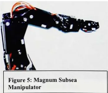
1.05
International
Submarine
Engineering
Ltd.
-Magnum
Subsea
Manipulators.
The Magnum
projectfeatured
the
creation of sevenfunction
master/slave
and
force
reflecting
manipulators.Some
of
the tasks that these
manipulators could
be
usedfor
are:clearing
sandand
mud,
jetting
and
brushing
operations,
wall
thickness
Figure
4: Mini Walker
Figure
5: Magnum Subsea
[image:13.529.88.256.511.671.2] [image:13.529.296.471.519.669.2]measurements,
cathodic protection
measurement,
anode
installation,
transponder
changeout,
stab
in
of
guidelines,
valve
turning
and
bolt
torquing,
cable
cutting, salvage, grinding,
drilling
holes,
and
intervention
[3]. This
magnum manipulator can
be
seen
in
Figure 5. It is
basically
a
large
robotic arm
that
can operate underwater.
The
arm
is
hydraulically
driven,
and
thus
has
the
limitation
of
having
umbilical
cording,
and
thus
preventing
it
from moving
acrosslong
distances.
However,
it
is
a good example of an
underwater workcell,
as such
may be
the
case
in
a pipe
that
is
being
searched.
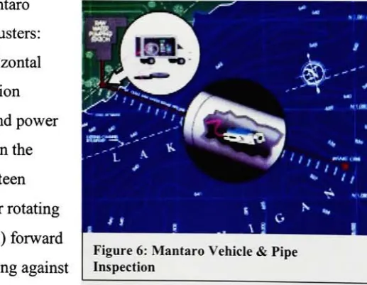
1.06 Aquatic Sciences Inc.
-Remotely
Operated Vehicles
(ROV)
for
Underwater
Pipeline
&
Tunnel Inspection.
This
project
wasdeveloped
by
Aquatic
Sciences Inc.
(ASI)
in St.
Catharines,
Ontario Canada. The
goal
ofthis
project
wasto
produce
adevice
(pictured
in
Figure)
that
could
inspect
flooded
pipelinesand
runnels,
and open
waterwaysvia
video and sonar
inspection.
These
vehicles are
designed
for
long-range
pipeline andtunnel
inspections.
The Mantaro
wasoriginally
designed
to
inspect
the
20 km
headrace
tunnel
atthe
Mantaro
hydroelectric
facility
in Peru [4]. With
the
long
distance
that the
Mantaro
couldtravel,
it
could utilize access points
ateach end
ofthe tunnel
[4]. The Mantaro
requires a
minimum
internal
diameter
of
3.0
meters.
However,
Aquatic
Sciences has
since made
smaller versions
to
fit
in
smaller
pipediameters.
The primary
useof
the
Mantaro
is
to
inspect
the
structural
integrity
of
variouspipelines.
The Mantaro
can also
be
retrofitted
to
add various
capabilities
suchas pipe
repairso
that
lines
canbe
inspected,
repaired,
and
re-commissioned
in
a
single multi-task[4]. The Mantaro is
unmanned,
but
once again needs
to
utilize
an umbilicalcord
to
communicate
information.
In
this case, the
cord
is extremely
long,
and
thus
quitebulky. The Mantaro
travels
via
twelve
variable
speedthrusters:
[image:14.529.217.476.483.683.2]intake flows
of
up
to
0.76
m/sec
(2.5
ft/sec)
[4]. The
smaller
ASI Pipecrawler
is
uniquebecause
it
moves on
two
clutched
tracks,
which can
be
cambered
to
provide
optimumtraction
[4].
1.07
Roper
Resources
-Scallop
Vehicle.
Perhaps
the
most
popular(and
most
copied)
remotely
operated submersible
is
the
Scallop
Vehicle
(Pictured
in Figure 7). The scallop
vehicle was one of
the
original
ROV's. In
this case, the
Scallop
utilizes24
VDC,
a color
ormonochrome
CCD
video
camera,
two
quartz
halogen lights
andthree thruster
motors
[5].
The
vehicle
is
completely
controlled
from
the
surface
via abuoyant
250-foot
tether
cable
[5].
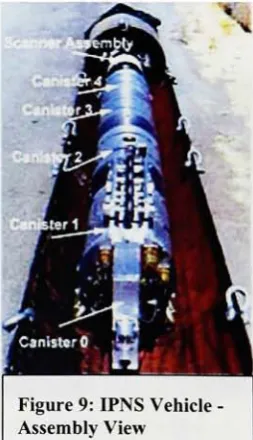
1.08 Inuktun Services Ltd
-IPNS Internal Pipe Non-Destructive Examination
System.
This
robot system was
developed
by
severaldifferent
corporations
for
Pacific
Gas
& Electric. The
vehicle was
designed
to
operate
in
twenty-two
inch
naturalgas pipe and
perform non-destructive examinations of
the
welds[6]. The IPN
examination system utilizes
three
pairs of
MiniTracs
for
the transport
platform
[6].
Furthermore,
the
system
is
capable
ofremote operation
to
a
distance
of
over2500
feet
withthe
supplied
tether
(umbilical
cable).
The IPNS
system can
be
seen
in Figures 8a
and
9. The
following
description follows
along
with
the
labels
in Figure 9. The IPNS
vehicle consists of
severalcanisters
that
are connected
together.
In
canister
0,
there
is
an
Ethernet
and
Video Mux
fiber
optic
transceiver
connection
[6].
Also,
the tether
cable attaches
directly
to this
canister.
In
canister
1,
the
power
source,
vehicle
control,
and video
switching
are all
housed. Canister 2
stores
the
couplant mixture
for
the
Ultrasonic
transducers.
Canister 3
stores
the
EMAT
(ElectroMagnetic
Acoustic
Transducer)
controland
sampling
system.
Finally,
canister
4
stores a remote
PC
system
running Windows 95. The
final
piece of
the
assembly is
the
scanner
assembly,
which
holds
and
Z2*it*M&-fSj
4
;
~
^*
**
/
V
?
-^
\a
Figure 8: IPNS Vehicle
rotates a color
camera, the
UT
and
EMAT
transducers,
and a
cleaning
brush.
1.09
The
Remote Underwater Characterization
System.
This
remote systemwas
developed
by
Idaho National
Engineering
and
Environmental Laboratory. Based
on
the
Scallop
vehicle
(see Figure
7),
this
system was
designed for
characterization andinspection
of water-cooled and moderated nuclear reactors and
fuel
storage pools
[7]. This
requiresthe
vehicle
to
operate underwater.
In
the
case of
the
Remote
System,
the
vehicle must
operateto
depths
of
up
to
twenty
feet.
As
was
previously
stated, the
Scallop
vehiclewas
the
main
focus
of
this
project.
The
Scallop
was modified
by
the
United
States Department
ofEnergy
so as
to
have
auto-depth control and vehicle orientation and
depth monitoring
atthe
operator
control panel
[7]. The Remote Underwater Characterization System
(RUCS)
wasdesigned
to
provide visual and gamma radiation
characterization,
even
in
confined or
limited
access
areas
[7]. The
basic
premise of
the
RUCS
systemis
that
it is
lowered
into
the
nuclearpiping
viaa
Plexiglas
window
that
has
already
been
cut.
Once
the
RUCS
is inside
the piping,
it
can
easily be
controlled
by
the user,
which
is
much safer
than
previous pipe
inspection
methods.
This
project was
anexcellent
demonstration
of an umbilical corded robot
that took
the
place
of several
humans
in
a
dangerous
job
setting.
1.10
Maverick Robot
-Robotic Inspection System for Storage Tanks.
This
system
uses a
remotely
operated robotic
inspection
vehicle
[8]. Utilized
for
inspection
of petroleum
tanks,
the
Maverick
robot
has
replaced
the
original
inspection
method of
having
a
human
workerclimb
into
the
tank themselves.
The Maverick
robot
has
revolutionized
the
petroleumindustry.
The
vehicle
travels
[image:16.529.351.478.446.666.2]data,
an onboard video system
to
record
inspections,
and a sonar
positioning
systemto
track
movement within
the tank
[8]. The
Maverick
robot
demonstrated
a cost
savingsof
$
1 85,000
in
lieu
of a conventional
inspection
method.
In
addition
to
reducing
costs, the
newinspection
system generated
less
waste,
eliminated
the
need
to
empty
and clean
the
tank,
and
limits
personnel exposure
to
petroleum-based gases
in
the
confined space of
the tank
interior [8].
2. AUTONOMOUS ROBOTS
2.01
University
of
Exeter
(U.K.)
-MINERVA
Project.
The MINERVA
project
stands
for
Machine Intelligence
for
Natural Environment
Recognition
and
Visual Analysis.
In
the
U.K.,
there
are several projects
being
developed
onthe
autonomousrobot
front.
Dr.
Sameer Singh
of
the
University
of
Exeter
is
developing
the
MINERVA
project.
This
projectis primarily
concerned
withdeveloping
intelligent
methods
for
scene analysis.
Robotics
allows
this
researchto
be implemented
on mobile platforms
to test theories
and software
for
real
applications such as robot navigation
based
on vision.
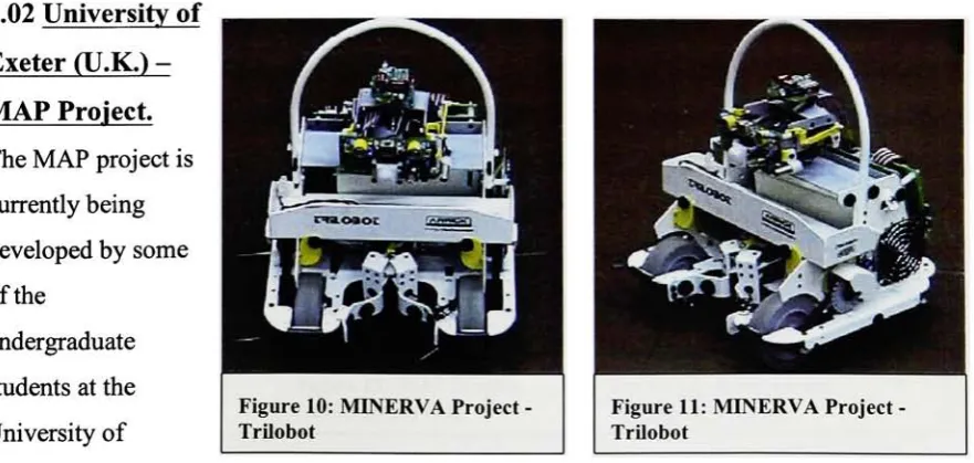
The
robot utilized
for
this
projectis
a
Trilobot
from
Arrick Robotics. This
robot can
be
seenin Figure 10
and
Figure 11. The
Trilobot
has
dimensions
of
12"x 12"x 12"and
weighs1 1
pounds.
It
utilizes
D-cell
batteries
to
poweritself,
and
has
several
sensory items
such as whiskers and sonar.
The Trilobot
is
utilized
with a camera mountedfor image
acquisition
[2]. The
output
ofscene analysis
is
used
in
conjunction
with othersensory information for
robot navigation and generates
instruction
for
robot
control.2.02
University
of
Exeter
(U.K.)
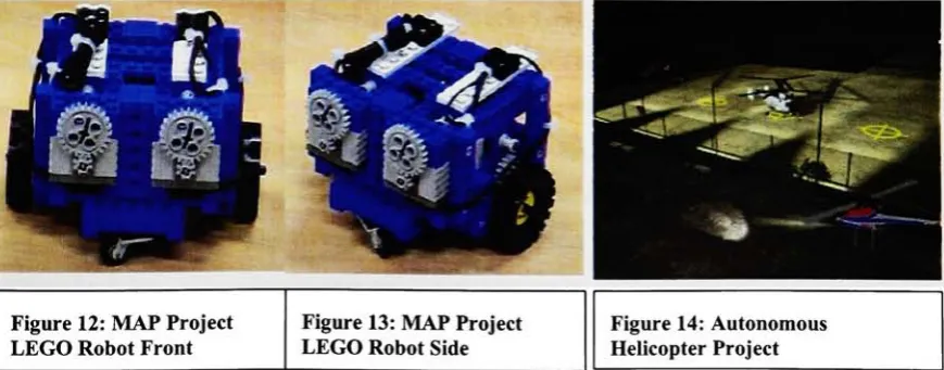
-MAP Project.
The MAP
project
is
currently
being
developed
by
someof
the
[image:17.529.51.492.475.684.2]undergraduate
students at
the
University
of
Figure 10: MINERVA Project
Trilobot
Figure 11: MINERVA
Project
Exeter. This
project
involves
developing
a compact robot
that
can
navigatethrough
pipelinesor mazes and generate a visual
map
that
shows
the
layout
[2].
Keeping
track
of
robot motiongenerates
the
visual map.
The
robot
is currently
being
programmed
to
measuredistances
andkeep
track
of
its location.
It
stores a sequence of actions and
measurementsthat
arefinally
translated
by
the
computer
into
a
map
or plan of
the
overall
structurethrough
whichthe
robot
navigated
[2].
Currently,
the
work
is in
its
initial
phases
to
design
this
system
using Lego
based
robots
[2]. These Lego
robots can
be
seen
in Figures 12
and
13. Each
ofthem
has
a
size of
12"x
12"x 12"and weighs
3
pounds.
2.03 Carnegie
Mellon
University
-Autonomous Helicopter Project.
Perhaps
one
of
the
most advanced autonomous robotics projects
to
date (Figure
14)
is
the
Autonomous
Helicopter Project
taking
place at
Carnegie Mellon. This
project
has developed into
a
systemthat
many
other universities and colleges
willtry
to
copy.
The
main
focus
ofthe
helicopter
project was
to
develop
a vision-guided robot
helicopter
which canautonomously carry
outa
goal mission
in any
weather conditions
whileusing
only
on-board
intelligence
and
[image:18.529.44.479.501.671.2]flight.
A
truly
autonomous craft cannot
completely
rely
on external
positioning devices
such
as
GPS
satellites or ground
beacons for
stability
and guidance.
It
must sense and
interact
with
its
environment.
On-board
vision was
the
primary
sensor
for
this
interaction
[9].
2.04 Worldwide Initiative
-RoboCup
Project.
The Robot World
Cup, RoboCup,
is
aninternational initiative
to
foster
AI
and
intelligent
robotics research
by
providing
a
standard
problem,
a soccer
game,
where a
wide range of
technologies
can
be
integrated
and examined
[10].
Such
ideas
as autonomous
robots
being
able
to
communicate
witheach other
to
complete
difficult
tasks
are what
have
been
fostered
through this
event.
Robots
must
be
able
to
communicatepositions
witheach
other,
decide
what
is
the
best
option
(pass,
or
shoot),
and
then
complete
the
task.
An
example of
these
robots can
be
seen
in Figure 15.
2.05
University
of
Salford
-Ball
Robot.
Dr. Ruth Aylett
from
the
University
of
Salford
brought forth
the
concept of
the
ball
robot,
Submar. This
project
involved
the
useof
whatis
called a
"society"of underwaterball-shaped devices.
The
workfor
this
project
is
being
completed
atthe
University
ofHelsinki
in Finland. Submar is
anintelligent
autonomous
miniature robot
for
the
monitoring
ofliquid
processes
[11]. These
robots
canmeasure
the
internal
stateof a
processand can perform small
tasks
such as
injecting
reagents and
taking
samples.
They
move
semi-actively
along
a process
flow,
changing
their
verticalpositions
using
diving
tanks
[11]. The
robots
incorporate
sensors and are able
to
communicate
withother robots and
withthe
process operator.
The
aim of
the
project
is
to
createa multi-robot
system,
a
"society"
giving
benefits
of
fault
tolerance,
flexibility
and
simplicity [11]. The
robot
is
a
third
generationprototype with a
10.8
cm outside
diameter,
and a
0.5W DC
motor
to
control
functions
like
the
diving
tank
and
the
chemical
tank.
Typical
sensors would
measure
internal
andexternal
temperatures,
conductivity,
pressure and
tilt.
Communication
between
robots
andwith
the
operator utilized
transceiver
boards
provided
by Radiometrix,
2.06
University
of
Portsmouth
-Pipe
Rover Project.
The
pipe
rover projectis
designed for
the task
of
inspecting
the
interior
of
large
holding
waterand
sewage outflowpipes and
ducts
[11]. The
vehicle
is
to
be
completely
autonomous,
with no
umbilical.It
will uselegs
and propellers
for
propulsion,
being
able
to
walkin
the
top
or
the
bottom
of
a
pipe,
and also
to
swim
[11].
Two-way
communication
is
to
be
by
ultrasonics,
and
it
will usebatteries
and/or compressed air as main
energy
sources
[11]. The
specificationsinclude
the
ability
to
swim at
2
m/s relative
to the water, to
crawl at
0.3
m/s and
to
have
a
total
missiondistance
of
1
km.
Some
problems
withthe type
of
ultrasonic communication usedin
this
project were
the
multipath characteristics of
pipesand
ducts,
including
the
behavior
of
the
signal at
bends;
the
attenuation of
the signal;
and
the
effect of
waterflow [11]. This
projectis
currently only in
the
design
phase.2.07
I.S.
Robotics
-Interactive
Robots.
I.S.
Robotics,
located
in
Boston,
Massachusetts,
is
one
company
atthe
forefront
of
developing
autonomousrobots.
The
company's robot expertise
has
captured
a majorinterest from
the
U.S.
military,
for
whoma
specialized
tank to
detect land
mines was
designed
[12]. The
tank
is
remote
controlled,
but it
can also make
many
decisions
where
to
go
onits
own[12].
2.08 AIS
-KURT
Robot.
The KURT
project was
developed
by
AIS
in Germany. The
moving
through
one of
these
sewer pipes.
KURT
has
an on-board
powersource,
andhas
the
ability
to
steer
autonomously
to
a given
target
point
in
the
sewer system
(26). The
autonomous
steering is done
by
using
the
topology
information downloaded from
a
digital
map
of
the
system
(26).
Utilizing
its
sensors,
KURT
can recognizelandmarks in
the
sewersystem
that
are represented on
the
map
as
it drives itself
towards the
goal
point.The
KURT
robothas
six wheels
(three
oneach side).
Each
side's wheels are
coupled,
however,
each
side
is driven
independently
from
the
other
(26). The
sensory
items
on
KURT include
inclinometers
(to
measure
the
incline
as
KURT
drives
it),
and
five fixed
and onerotating
ultrasound
transducers
(26).
All sensory
items
are
linked
to
an onboard microcontroller
for
low
level
programming,
while
higher
processing
is done
with a
PC. KURT
also
has
an on
board CCD
camera
that
sends
data
via radio
frequency
to the
outside world
(26). The
most
recent version of
the
KURT
robot
canbe
seenin
Appendix
A,
Figure 18. The KURT
robot
is
agood
demonstration
of an
autonomousrobot
in
usetoday
for
the
purpose of
pipeinspection.
It
utilizes several
sensory
items,
and an onboardmicrocontroller
to
transmit
data
(from
the
video
camera)
back
to the
user.
However,
KURT
does
not complete
any
set
task,
other
than
navigating
the
sewerpipe system.
3. Case Studies
in
Autonomous
Robotic
Communication Projects
3.01
Introduction;
There
areseveral projects
that
are
currently
at
the
forefront
of
the
autonomous robotics
scene.
The
following
summarizes
two
of
these
projects.
The
first is
the
"Army-Ant"project
that
is
taking
place
at
Virginia
Polytechnic Institute
and
State
University. The
second
projectis
the
worldwide
initiative
discussed
earlier
in
this
paper
called
the
RoboCup. Both
of
these
projects will allow one
to
see
how
several autonomous
robots can
be
usedin
conjunctionwith each other
to
complete
a specific
task.
3.02
Case Study #1:
Virginia
Polytechnic Institute
and
State University:
Armv-Ant
Cooperative
Lifting
Robot.
3.02.1
Top
Level Concept:
The
army
ant robot concept
is
onethat
wasintended
to
be
inexpensive
and simple.
The
main goal was
to
have
all
the
robotsbe physically
identical,
thus
constituting
a
homogenous
team
of robots
[13].
They
derive
their
usefulness
from
their
material-handling
system
[13]. Under
this
scenario, many
small robots would
be
deployed
in
large
numbers
to
cooperatively lift
and
transport
objects.
The
small
tank-like
robots wouldposition
themselves
around
the
periphery
of a
large
object,
"squeeze"
themselves
underneathit,
and
then
proceed
to
move
in
a coordinated
way
to
transport their
load [13].
In
the
typical
commercial
robotic,
material
handling
system, the
vehiclesare
eitherhighly
constrained,
or
automated guided vehicles
(AGV's).
The
army-ant
system wasdesigned
to
be
muchmore
flexible
than
the
typical
robotic movement system.
There
wereseveral goals of
the
army
antsystem.
The
following
summarizes some of
the
following
goals.
3.02.1.1 Robustness: All
the
robots should
be
identical. This
feature
will make
them
modularand
interchangeable.
If
one of
the
robots
fails,
it
caneasily
be
compensated
for
by
any
of
the
other robots
in
the
system.
This
will also
greatly simplify
the
programming
of
the
robots
[13].
3
.02.1
.2Flexibility: All
the
robots
in
the
systemcan
carry
either palletized or unpalletized
loads [13].
3.02.1.3 Small Size:
All
the
robotsare
designed
to
be very
smalland
lightweight. These
robots are
easily
stored and
highly
maneuverable.If
there
is
anoperation
that
requires more
power,
more robots
canbe
added,
as opposed
to
adding
bigger
robots
[13].
3.02.1.4
Low Expense:
Since
all
the
robots
in
the
system are
identical,
mass production of
them
would
be
quite easy.
Because
of
this,
the
robotsare also expendable
in
military,
space,
or
hazardous
environmentapplications
[13].
3.02.1.5 Simplicity: To
achieve
the
desired
mass production of
identical
robots,
a simplistic
approach
has
to
be
taken.
The
robots
cannot,
and are
not,
highly
sophisticated.
Low
cost
is
directly
correlated withthe
technological
simplicity
of
the
devices [13].
off-the-shelf components as much as possible
[13]. Specific design
requirements madeit
so
that
the
vehicle needed a
low
profile
in
order
to
minimize vertical
lifting
of
the
payload[13].
Furthermore,
there
needed
to
be
a zero
turning
radius
and, eventually,
a
swiveling,
lazy
susanstyle
top
surface
for
the
robot
[13].
In
this way,
several robots
maintaining
a
friction-enforced contact with
the
underside
of a
rigid
payload would not
have
to
implement
differential steering
trajectories
during
turning
maneuvers.Because
of
this
zero-turning-radius
need,
treaded,
tank-like
vehicles were chosen
because
they
have
simplekinematic
models and are
relatively easy
to
construct.
Because
the
locomotion
was not
to
be
a researchconcern,
off-the-shelf
radio-controlled
tank-like
vehicles werepurchased
[13]. This
provided
the
chassis
tray,
together
with
drive
axles and
wheels,
bearings
and
asuitable gear
train.
Other
areas
that
were worked
onduring
the
initial
prototyping
ofthe
army
ant were as
follows.
3.02.2.1
Power
Source: To
power one of
the
tanks,
two
6-volt,
4.2
amp-hour
lead
acid
batteries
were
used.
For stability
during
the
lifting
of
heavy
objects, these
were also
considered
ascounterweights and were
located
in
the
bottom
of
the
chassis
tray,
under all
ofthe
other
circuitboards [13].
The resulting
inaccessibility
promptedthe
placement of
the
recharging
circuitadjacent
to the
battery
terminals,
with a
1
12-volt
AC
power cord routed
through the
body
[13].
Two
connections
to the
battery
were
made,
one
to
a
five-
volt
regulator
and
filter
board,
and
the
other
to the
12-
voltsupply.
Such
connections across
the
two
batteries
resultedin
a
loss
of
charging
efficiency.
This
problemis
addressed
in
the
second-generationprototype
[13].
3.02.2.2 Drive Train: Since
the
motors
that
wereincluded in
the
RC
kit
were
high
speed,
low
torque,
another gearboxhad
to
be
used.
The
newgearbox reduced
the
RPM
no-load speed
to
26:
1
[13].
The resulting
tread
speed was
7.3
feet
per minute.
Both
of
the
gearboxes were
controlled
using H-bridge
motor
driver
circuits.
3.02.2.3 Lift Mechanism: The
lift
mechanism
is
one of
the
things
that
separates
the
Army
Ant
projectfrom
others
that
have been
reviewed
in
this
paper so
far. The lift
mechanism
in
the
army
ant
projectrequired
that
it
support much more weight
than
the
actualweight of
the
robot,
but
not
consumemore current
than the
motor
drivers
could supply.
Many
choices
were
considered,
but
the
decision
finally
came
down
to using
a pneumatic
bladder. The
contact area
is
available),
inflates
the
bladder,
and
then
generates
the
250
lift
pounds offereethat
it
can
to
pick
up
the
piece.
Because
the
robot weighs
less
than
twenty
pounds,
applying
these types
of vertical
loads
at
the
front
of
the
robot could
easily
tilt
the treads
off
the
ground.Therefore,
the
front basket
of
the
robot was supported
directly by
the
floor
by
attaching
ball
casters
to
its
underside
[13].
3.02.2.4 Sensors: For
the
first
generation
prototype,
the
goal was
only
to
pickup
objects.
Because
of
this,
the
robot was
incapable
of
navigation,
having
no
goal-seeking
or obstacle
avoidance
sensory
apparatus
[13].
Therefore,
lever
microswitches
sufficedto
trigger
the
lifting
response,
and
to turn
it
off
whenlifting
wascomplete
[13].
3.02.3 Second Generation Prototype:
By
the time
a
second-generationprototype rolls
around,
much of
the
groundwork
is
complete.
The initial
prototype
wentthrough
many
of
the
problems
that the typical
prototype always
does.
The
second-generation prototypeallows
for
the
designer
to
begin creating
some of
the
more
desirable
andhigher level
thinking
design
elements.
For
the
army
ant
project, the
mostobvious shortcomings were mechanical.
The
off-the-shelf chassis was molded
plastic,
and
wheelswithin
the tank treads
were attached
withtorsional
springs as
shock absorbers.
Thus
a
verticalload
resulted
in
excessivestatus
signals,
and
closed-loop
motion
feedback.
In addition,
it
was
necessary to install
a
swivel-top
and
force
sensors needed
to
be
attached and
interfaced
[13]. The
second-generation
prototype
can
be
seen
lifting
a
box in Figure 18.
3.02.3.1
Power
Source:
Because
of space
considerations,
it
was
decided
to
use
2-volt
D-size
lead-acid
"gel-cell"batteries.
These
were required
in larger
numbers,
but had
the
advantage
of
being
distributed
throughout the
available space
in
the
chassis
[13].
3.02.3.2 Drive Train:
The
drive
mechanism
is
essentially
the
same as
the
first
generation
robot.
However,
in
this
second-generation
case, the
chassis
had
its
materials selected
and
assembled,
ratherthan
relying
onmanufactured
products[13].
The
tread
material was made
from
nylon reinforced
rubberconveyor
belting,
stitchedand glued
together to
form
a closed
loop. These
treads
ride between
edge
flanges
onreinforced
PVC
wheels.
High
torque
DC
motors were again used
for
the
drive
train,
with1
:
1
external gearing.
Once
again,
an
H-bridge
motor
driver
circuit was
usedto
drive
the
motors.
3.02.3.3 Lift
Mechanism: The
second-generationprototype uses a
lift
mechanism
consisting
of a single moveable
flat
top
platform.
Instead
ofthe
air compressor and
bladder,
it
requires
two
lift
motors,
each with a
large
gear reduction.
Twin
jackscrews
give
the
top
platform
two
degrees
of
freedom:
vertical(both
jack-screws moving in
the
same
direction)
and
tilt
(one
raising,
one
lowering)
[13]. Even
the twin
jacks did
not compare
to
the
mechanical
advantage
of
the
pneumatic
lift,
so
high
reduction gearhead motors were chosen
to
drive
the
screws
[13]. The
turning
threaded
rodsproduce
linear
actuation
through
recirculating
ball
bearings
in
a closed guidea
"ball"
screw
[13].
Recirculating
balls
are much more efficient
than
a
simplelubricated
threaded
guide.
The
advantage of
the two-degree-of-freedom
system
is
three-fold.
First,
it
makes
the
entire
top
platform a
lifting
wedge.
This
reduces
the
angle
between the
platformand
the
ground when
the
platform
is
raised and
lowered.
Second,
the
platformis free
to
move
in
a
purely
vertical
direction.
Finally,
the
single platform
greatly
facilitates
"backing-out,"since
the
down-tilt
maneuver can
be
performedwhile
the
robot
is in
3.02.3.4 Sensors: The
second
generation
army
ant was equipped with
many
of
the
same
sensors
that
are employed on
many
other
projects
today:
infrared for beacon
and
direction-finding,
as well as obstacle
detections,
ultrasonic
for
range
finding,
and
whisker-type contactswitches
for
collision
detection
[13]. The details
of
their
implementation
willnot
be
discussed
at
this time.
3.02.3.5
Force
Sensors:
The
goal of
implementing
force
sensors was
to
show
that
it
would
be
possible
to
utilize several robots
to
carry
an
object,
and
have
eachof
them
carry
the
sameamount of
the
load. Equal force distribution implies
both
force-sensing
and
signaltransmission
[13]. Simple
strain gages could
be
usedto transmit
the
signals
with relativeease.
The
strain gages are applied
atloading
pointsthat
supportthe
top
platform and
they
are
cushioned
by
rubber shock-mounts.
Also,
since
it
is desirable
to
have
the
horizontal forces
measured, the
leader has
the
sensory
attachment
to
calculateit.
Then,
the
rest of
the
robots
follow
in
a master/slave setup.
3.02.3.6
Software:
All
of
the
software
for
the
army
ant project was programmed
in C for
convenience.
3.02.4
Conclusions:
The
army
antproject
demonstrates
how
one
group
went about
the
design
of anautonomous
systemofrobots
and
that
design's
creation
into
an
initial
and
secondary
prototype.By
setting
goals
for
each of
the prototypes,
it
was more
easily
evident
how
to
break
up
the
workthat
needed
to
be
done for
each
yearof work.
The
next case
study
features
the
RoboCup
initiative. The
RoboCup
is
anotherinteresting
case,
because
it
requires
a
tremendous
amountof
communicationbetween
robots
to
get
the
system
to
work.
The
development
of a systemfor
this
project
is
quite
abit
more extensive
than that
of
the
army
ant
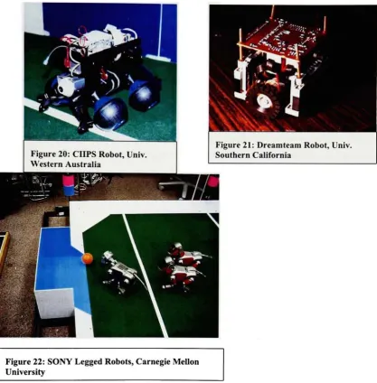
project.3.03 Case
Study #2; Carnegie Mellon University; Towards Collaborative
and
that
will show a
learned,
low-level
behavior
that
is
necessitated
by
the
multiagent nature of
the
domain,
namely shooting
the
ball
[14].
Some
of
these
robots can
be
seen
in Figure 19.
3. 03.2 Multiagent Learning:
Multiagent
learning
is
"learning
that
is
done
by
severalagents and
that
becomes
possibleonly
because
several agents are
present"[15]. It
is
possiblefor
a single agent
to
be
learning
in
a multiagent scheme
if
the
single agent
is
learning
to
interact
withthe
other agentsin
the
scheme
[14]. This is especially
true
if
the
learned
behavior
enables
additional multiagentbehaviors,
perhaps
in
which more
than
one agent
does
learn,
the
behavior is
a
multiagentbehavior.
This
is
the
case since
the
learning
wouldnot
be
possible
if
the
agent were
isolated
[14]. In
the traditional sense,
machine
learning
involves
a single agent
that
is
trying
to
maximize some sort of
utility
function
withoutany knowledge
of whether or not
there
are
otheragents
in
the
environment
[16]. When using
the
idea
of
teaching
asingle
behavior
to
a
single
agent, the
justification
can
be
that the
knowledge
of
the
behavior
canbe
used as a
basis
for
morecomplex
interactive behaviors. Some
examples
ofsingle agents
learning
in
a
multiagent environment
are
things
such as reinforcement
learning,
whichincorporates
information
that
is
gatheredby
anotheragent.
This
is
considered
to
be
multiagent
because
the
learning
agentis
learning
to
interact
withanother agent:
the
situation
only
makes sense
due
to the
presenceof
multipleagents
[14]. Another
such example
is
anegotiation scenario
in
which one agentlearns
the
negotiating
techniques
ofanother
using Bayesian
Learning
methods
[17]. One final
example of multiagent
learning
is
one
in
whichonly
one of
the
agentslearns
a
training
scenario
in
which a novice agent
learns from
a
knowledgeable
agent
[14]. The
novicelearns
to
drive
on a somewhat simulated
track
from
anexpert agent whose
behavior
is fixed [14]. The
one
thing
that
all of
the
above examples show
is
that
the
learning
agent
is
"interacting"
3.03.3 Robotic Soccer:
There
was a
groundbreaking
system
in
robotic
soccerdeveloped
at
the
University
of
British
Columbia
called
the
"Dynamo
System."In
this system,
severalrobots were
supported,
but
most of
the
work was
done
in
a
1
vs.
1
scenario.
This
systemutilized a
decision-making
strategy
called
"reactive
deliberation"[14]. This
decision-making
strategy
was used
to
choose
from
seven
hard-
wired
behaviors [14]. Those
that
worked on
the
robotic soccer game at
Carnegie Mellon developed
a similar system.
In
this system, the
robots are smaller
than the
Dynamo
system, play
five
on a
team
and use
Infrared
communications
rather
than
radio
frequency
[14].
The Dynamo
systemfound
that the
best
simulation
scoring
rate
was70%. Note
that
in
the
Dynamo
system, the
approach was
to
develop
asophisticated robot system
withmany
advances
capabilities.In
the
Carnegie
Mellon
system,
the
approach
wasto
focus
ona
simple,
robustdesign
that
willenable
the
designer
to
concentrate
their
efforts on
learning
low-level
behaviors
andhigh-level
strategies
[14].
Either
approach seems
to
be
validin
obtaining
the
desired
results of a
soccersystem
ofrobots.
3.03.4
Learning
a
Low-Level
Multiagent
Behavior:
The
focus
of
this
section
willbe
the
ability
to
shoot a
moving
soccerball [14]. One
could
considershooting
a
soccerball
to
be
a
single agent
behavior.
However,
it
canbe
considered a multi-agent
behavior because
another
agent must move
(pass)
the
ball
to the
shooter.
For
the
Carnegie
Mellon experiment,
there
were always
two
(2)
agents: a
passerand a shooter.
The
passer accelerates as
fast
as possible
towards
a
stationary
ball in
orderto
propelit between
a shooter and
the
goal
[14]. The
resulting
speed of
the
ball
is determined
by
the
distance
that
the
passer started
from
the
ball
[14].
The
shooterstask
is
to time
its
acceleration so
that
it interprets
the
ball's
path and
redirects
it into
the
goal
[14]. The shooting
robot must accelerate at a constant rate once
it
decides
to
begin its
approach.Therefore,
the
behavior
to
be learned
consists ofthedecision
until
it
is moving in
the
right direction
along
this
line. The
line along
which
the
shootersteers
is
the
steering line. The
method
in
which
the
shooter
choosesthe
steering
line
is
called
its aiming
policy
[14]. There
are several
different
types
of
behavior
that the
creatorsof
the
Carnegie Mellon
project used
to
generate
their
full
prototype
soccerrobots.
There
werestudies
in both fixed ball
motion and varied
ball
speed.
This
case
study
will
deal
with
the
fixed
ball
motion
only
since
the
varied
ball
speed exceeds
the
scopeof
this
paper.3.03.5 Fixed Ball Motion:
The
initial
experimentation
withthe
Carnegie
Mellon
soccerproject
dealt
with
the
soccer
ball
being
passed withthe
same
trajectory
and
the
same
speedfor
all
training
and
testing
samples
[14]. Since
the
ball
motion was alwaysfixed,
the
shootercould always aim at
the
same point wide
ofthe goal,
guaranteeing
that
if
contact
wasmade,
the
ball
would
be
propelled
in
the
right direction
[14]. The shooting policy
that
was
used wasas
follows:
the
shooter could score
consistently
if it began
accelerating
when
the
ball's
distance
to
its
projected point of
intersection
whenthe
agent's path reached
1 10
units
[14].
When using
this type
of
policy, the
shooter scored
60.8%
ofthe
time.
3.03.6 Inputs:
The Carnegie
Mellon
soccerrobot
projectimplemented
the
use
of a
neuralnetwork.
The
goal of
this
network was
to
have
the
networkoutput
whetherstarting
to
accelerate
in
a world
statedescribed
by
the
input
values was
likely
to
lead
to
a goal
(outputs
close