Distributed Power Quality Improvement in Residential Microgrids
Yahya Naderi
1,2*, Seyed Hossein Hosseini
2,3, Saeed Ghassem Zadeh
2, Behnam Mohammadi-Ivatlo
2Juan C. Vasquez
1, Josep M. Guerrero
11Department of Energy Technology, Aalborg University, Aalborg 9220, Denmark {Yna, Juq, Joz}@et.aau.dk
2 Faculty of Electrical and Computer Engineering, University of Tabriz, Tabriz, Iran {Y.naderi, Hosseini, G_zadeh, bmohammadi}@tabrizu.ac.ir
3 Engineering Faculty, Near East University, 99138 Nicosia, North Cyprus, Mersin 10, Turkey * Corresponding Author
Abstract
The importance of power quality issue on micro grids and also the changing nature of power system distortions will lead the future power systems to use distributed power quality improvement (DPQI) devices. One possible choice of these DPQIs are multifunctional DGs that could compensate some harmonics in the location of generation and prevent the harmonics to enter main power grid. In this paper a control method based on virtual harmonic impedance is presented for these multifunctional DGs and the effect of the location of these DGs on compensation procedure is studied with simulating the different situations. Finally a comparison is presented between different states of using DGs as PQI devices. To verify the feasibility of the control method a comparison is done between the presented method results and IEEE power quality standard limits.
1. Introduction
Nowadays the power quality issue in power electrical systems has gained a lot of attention not only because of power system faults or distortions made by huge power consumers of electricity, but also the distributed nature of disturbances caused by non-linear loads and DGs has been supposed as a new threat to power quality of electrical power system. In the previous ordinary power systems, the power quality problems was just limited to unbalances caused by faults, switching transients related to huge loads and harmonics created by non-linear load currents. The power system has been experiencing changes in configuration, generation sources size and nature, non-linear load quantity incensement and increase on awareness of costumers. The increasing number of non-linear loads in residential applications is a new concern of power grid, since it will cause distributed distortions that couldn’t be solved using traditional compensation methods. Since in power systems of today, small residential non-linear loads have a significant portion of power quality disturbances in electrical grid, then they should also have a role in solving these problems. Taking into account that most of the DGs use power electronic based inverters, and considering the cost of inverters, sometimes will make a doubt about development of more small DG units.
Although some utility managers consider small DGs, non-cost efficient, by adding some other features and capabilities to these systems the doubt on cost effectiveness of DGs will be vanished. Some of these capabilities would be harmonic compensation, unbalances compensation, over and under voltage compensation. Although the concept of Distributed Generation was just referring to power plants with the capacity of Several KWs or bigger generation plants earlier, nowadays even the power generation sources of 1 KW are also called as a distributed generation [1, 2]. Most of the DG inverters have the insufficient output voltage to be used as a part of electrical power system, so there should be a voltage converting stage inside the converters. The two usual converter systems used for DG applications are direct (DC/AC) converters [3, 4], that outputs the AC to be used in power system and double stage converters like (DC/DC + DC/AC), that fixes the DC voltage level to an appropriate level in the first stage and then converts this DC voltage to applicable AC voltage. Many researches have been done in controlling inverters in recent years to have pure sinusoidal AC voltage or current in the output but this is not all the capability that a DG inverter is supposed to have [5]. Although other researches have focused on optimization methods to solve power quality problems, such as PSO, ICA, bee and genetic algorithms [6-8], the better way to improve the operation of system is to get other functionality of these inverters.
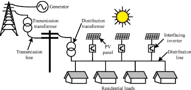
Fig. 1. An overall view of residential home with PV installation
These sections will be followed by some simulation results of different compensation states with DGs placed in different locations, and comparison tables that will compare results with the results without any compensation and also with some IEEE and IEC power quality standards to verify the feasibility of the method.
2. The System modeling
In Fig. 1 a section of distribution power system is shown, this system contains residential houses, the photovoltaic system connected by interfacing inverters and control system configuration. To explore the mentioned power grid, it is better to start with residential loads, it is obvious that various kinds of non-linear loads are being inserted in power grids and most of these loads are related to home appliance, computers and power electronic based devices. The residential grid model that is shown in Fig. 1 is a combination model of several devices to show the effects of non-linear loads and harmonic compensators on an electrical power system. To have a detailed vision of these devices, a CFL and a PC are selected as a sample of non-linear loads and the harmonic components of these devices are analyzed in Table 3. It is worth noting that the provided data are taken from [9, 10] in which the harmonic current of different home appliances are measured practically.
The interfacing inverters are connected to distribution system model to absorb harmonics and improve the power quality of the grid, in this case DG inverters work as an active power filter that will absorb certain harmonics by the means of virtual harmonic impedance. To become familiar with the concept of virtual harmonic impedance, a section is dedicated to explain the concept of Virtual harmonic impedance and the harmonic compensation method based on this concept. The overall micro grid to simulate the idea will be a 7 node system with linear and nonlinear loads that represent the residential distribution system with power generation and power consumption that is connected to grid. A simple model of the residential grid is shown in Fig. 3 and it can be seen that there are two predefined locations for DGs and also there are linear and non-linear loads. In this system current controlled DGs are used to compensate the non-linear loads current in order to have a pure sinusoidal voltage at PCC and also sinusoidal current to be injected or absorbed from grid.
The non-linear loads are assumed to be residential loads like CFL and PC as shown in Table 3, the other parameters of system are presented in Table 1.
2.1. Virtual harmonic Impedance
In this paper DG inverters are controlled as virtual harmonic impedance to absorb harmonic currents from nonlinear loads. The operation of virtual harmonic impedance is such that, it emulates the behavior of physical impedance without connecting any physical elements to circuit. Virtual impedance appears as a pre-defined relation between voltage and current of controlled inverter, such that it can show different behaviors in different situations. It can be present at fundamental frequencies as well as harmonic frequencies. Virtual impedance will act like an infinite resistance against some frequencies and it will present a low resistance when encountering some other frequencies that would introduce different applications.
The fundamental frequency virtual impedance is used to help power flow control while the harmonic frequencies virtual impedance is mainly used to control the harmonic current flow and also it is used in active harmonic compensation applications [11-13]. A harmonic compensation method using Virtual harmonic Impedance is performed in a voltage – controlled DG unit in which DG acts as a controlled voltage source that is in series with output impedance of ZDG h− [14] . The output voltage of DG is controlled in accordance to the harmonic voltage of point of common Coupling (VPCC ), with a positive
feedback gain (G) that is shown in the equation (1).
DG h PCC h
V − = − ×G V − (1)
From the above equations it can be concluded that, the equivalent harmonic impedance of DG, ZDG h total− − can be
calculated by the equation (2). / (1 )
DG h total DG h
Z − − =Z − +G (2)
In which G can take values from −1 to∞, since in the harmonic frequencies the grid impedance is mainly inductive, this method can be used for microgrid applications. In current-controlled inverters, DG acts like a shunt active power filter that absorbs the harmonic current from non-linear loads or it injects harmonic current to grid to feed the non-linear loads and prevent the main grid to inject harmonics to micro-grid. Then the PCC voltage is finally harmonic free and total harmonic distortion of
PCC
V is decreased. One of the methods of operating as an APF is to use the concept of virtual resistive to implement resistive active power filter (R-APF) [12]. In this method the harmonic components of grid voltage is extracted and then the current reference for DG will be;
* /
h DG Grid h h
Table 1. System parameters
Parameter Value Distribution Voltage
Line Impedance
Load 1
Load 2
Load 3
DG1 Capacity
DG2 Capacity
230 V (RMS) (40 Ω + 150 mH) /KM
1 kW
0.8 kW
0.5 kW+ 0.5 kVAR
8 Kw
8 Kw
In which, Rh is the value of virtual harmonic resistance and DG acts like a virtual harmonic resistor only in harmonic frequencies. It is worth noting that most of the grid connected small DGs are current controlled, so this method is more popular.
2.2. Inverter Control based on Virtual Harmonic Concept
[image:3.595.69.279.433.527.2]In this paper the PV controller is selected as a two-stage controller, a DC/DC converter to create the desired output DC voltage and do the maximum power point tracking, followed by a DC/AC converter to connect the system to power grid. Since the focus of this paper is on second stage and similar works has been done before for DC-DC stage, there is no need to go in details about the first stage of conversion [15, 16]. The second converter is a current controlled voltage source converter that will be controlled as an R-APF.
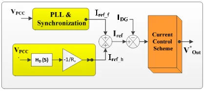
Fig. 2. An overall scheme of current control method
The controller used in second stage gets a current reference and then tracks it. The overall scheme of a current controlled controller is shown in Fig. 2. The current reference introduced in this application is formed as a combination of fundamental and harmonic current references as followed;
*
DG ref f ref h
I
=
I
−+
I
− (4)/
ref h PCC h h
I − =V − R
(5)
For tracking the reference Current, P+Resonant controller is used, as it is obvious from Equation (6) for each harmonic frequency a parallel resonant term is added to the controller.
2 2
1,5,7... 2
2
ih ch
C P
h ch h
K s
G K
s s
ω
ω ω
=
= +
+ +
(6)
3.Simulation Results
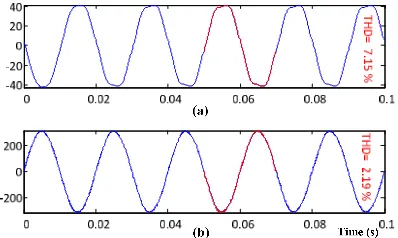
The simulations are performed in four sessions in Matlab/Simulink, the first results will show the grid voltage and current without any compensation, in the second one the DG located in Node 1 will act as an APF, the third simulation presents the results when only DG2 (located at Node 4) acts as an APF and in the last session both of the DGs will take part in the process of compensating. A comparison between results is presented in Table 4. From the figures 6-9 and Table 4 the comparison results shows that the minimum THD for
PCC
V occurs in the situation that DG1 and DG2 are compensating non-linear load harmonics, but also it is obvious that in this situation that grid Compensates harmonics, the micro grid gets a distorted current from grid with THD of 7.15 %. The minimum amount of grid current THD occurs when both DG1 and DG2 are compensating non-linear load currents with amount of 1.83 %. The switching frequency is set to be 10 kHz and the inverter used in the DC/AC stage of converter is a single phase H-Bridge converter.
Table 2 and Table 5 presents the voltage and current distortion limits based on IEEE 519 standard [17], it can be seen that the voltage and current distortion of the PCC is below the limits.
Table 2. Voltage distortion limits standard
Bus Voltage VPCC
Individual harmonic (%)
Total harmonic distortion THD
(%)
1
V≤ kV 5.0 8.0
1kV ≤ ≤V 69kV 3.0 5.0
69kV≤ ≤V 161kV 1.5 2.5
161kV V≤ 1.0 1.5 a
4.
Conclusion [image:3.595.315.528.451.535.2]Table 3. Harmonic details of home appliances
Device Name
Data Harmonic Load Current Data
Type 1st 3rd 5th 7th 9th 11th 13th
CFL Mag 0.15 0.13 0.09 0.07 0.07 0.06 0.039
Ang 21.2 53.9 105.5 169.4 -134.8 -84.2 -21.8
PC Mag 0.83 0.65 0.41 0.160 0.101 0.121 0.12
Ang 0.50 1.60 3.60 8.60 58.11 168.6 178.0
[image:4.595.97.499.88.292.2]Fig. 3. A simplified view of simulated residential power grid
Table 4. Comparison results
THD % VPCC IGrid ILoad1 ILoad2 ILoad3 VLoad1 VLoad2 VLoad3 Inll-1 Inll-2
No DG 2.19 7.15 1.79 1.75 0.46 1.79 1.75 1.60 22.17 8.09
DG 1 2.487 6.96 2.53 2.43 0.16 2.53 2.43 2.30 23.26 7.65
DG 2 2.04 2.49 2.01 2.04 0.07 2.01 2.04 2.06 23.13 8.22
[image:4.595.76.514.416.482.2]DGs1&2 0.38 1.83 2.26 2.10 0.04 2.26 2.10 1.97 23.09 8.61
Table 5. Current distortion limits for systems rated 120 V through 69 kV
Maximum harmonic current distortion in per cent of IL
Individual harmonic order (odd harmonics) a
ISC/IL 3 ≤h <11 11≤h < 17 17 ≤h < 23 23 ≤h < 35 35 ≤h ≤ 50 TDD
< 20 4.0 2.0 1.5 0.6 0.3 5.0
20 < 50 7.0 3.5 2.5 1.0 0.5 8.0
50 < 100 10.0 4.5 4.0 1.5 0.7 12.0
a Even harmonics are limited to 25% of the odd harmonic limits above. Where Isc = maximum short-circuit current at PCC &
IL = maximum demand load current (fundamental frequency component) at the PCC under normal load conditions
Fig. 4. (a). Grid Current (b) VPCC of Residential grid without
[image:4.595.342.502.546.678.2] [image:4.595.75.274.549.668.2]Fig. 6. (a). grid current (b) DG 2 current (c) VPCC of residential grid with DG 2 compensating non-linear loads
Fig. 7. (a). grid current (b) DG 1 current (c) DG 2 current (d) ) VPCC of residential grid with both DGs 1 & 2 compensating
non-linear loads
5. References
1. Arrillaga, J. and N.R. Watson, Power system harmonics. 2004: John Wiley & Sons.
2. Ackermann, T., G. Andersson, and L. Söder, Distributed generation: a definition1. Electric Power Systems Research, 2001. 57(3): p. 195-204.
3. Oskuee, M.R.J., et al., A new multilevel voltage source inverter configuration with minimum number of circuit elements. Journal of Central South University, 2017. 24(4): p. 912-920.
4. Sadeghian, H., M.H. Athari, and Z. Wang. Optimized Solar Photovoltaic Generation in a Real Local Distribution Network. in Innovative Smart Grid Technologies Conference (ISGT), 2017 IEEE Power & Energy Society. 2017. IEEE.
5. Naderi, Y., et al. A new strategy for harmonic minimization based on triple switching of multilevel converters. in Electrical Engineering (ICEE), 2013 21st Iranian Conference on. 2013. IEEE.
6. Etesami, M., N. Farokhnia, and S. Fathi. A method based on imperialist competitive algorithm (ICA),
aiming to mitigate harmonics in multilevel inverters. in Power Electronics, Drive Systems and Technologies Conference (PEDSTC), 2011 2nd. 2011. IEEE.
7. Yahya Naderi , S.Jafarzadeh, Seyed Hossein Hosseini, Saeed Ghasemzadeh. Selective Harmonic Elimination of Multilevel inverter by the mean of PSO Algorithm. in ICEEE 2016, Istanbul , Turey. 2016.
8. Kavousi, A., et al., Application of the bee algorithm for selective harmonic elimination strategy in multilevel inverters. IEEE Transactions on power electronics, 2012. 27(4): p. 1689-1696.
9. Dwyer R, Khan AK, Mcgranaghan M, Tang L, Mccluskey RK, Sung R, Houy T. Evaluation of harmonic impacts from compact fluorescent lights on distribution systems. IEEE Transactions on Power Systems. 1995 Nov;10(4)
10. Nassif AB, Yong J, Xu W. Measurement-based approach for constructing harmonic models of electronic home appliances. IET generation, transmission & distribution. 2010 Mar 1;4(3):363-75. 11. Li, Y.W. and C.-N. Kao, An accurate power control
strategy for power-electronics-interfaced distributed generation units operating in a low-voltage multibus microgrid. Power Electronics, IEEE Transactions on, 2009. 24(12): p. 2977-2988.
12. Pogaku, N. and T. Green, Harmonic mitigation throughout a distribution system: a distributed-generator-based solution. IEE Proceedings-Generation, Transmission and Distribution, 2006.
153(3): p. 350-358.
13. Vasquez, J.C., et al., Hierarchical control of intelligent microgrids. IEEE Industrial Electronics Magazine, 2010. 4(4): p. 23-29.
14. Wang, X., et al., Virtual-impedance-based control for voltage-source and current-source converters. IEEE Transactions on Power Electronics, 2015. 30(12): p. 7019-7037.
15. Varesi, K., M. Sabahi, and E. Babaei, Performance and Design Analysis of an Improved Non-isolated Multiple Input Buck DC/DC Converter. IET Power Electronics, 2017.
16. Nouri, T., et al., A Novel Interleaved Nonisolated Ultrahigh-Step-Up DC–DC Converter With ZVS Performance. IEEE Transactions on Industrial Electronics, 2017. 64(5): p. 3650-3661.