City, University of London Institutional Repository
Citation:
Zomorodian, M., Belarbi, A. and Ayoub, A. (2017). Finite element model for predicting the shear behavior of FRP-strengthened RC members. Engineering Structures, 153, pp. 239-253. doi: 10.1016/j.engstruct.2017.10.033This is the accepted version of the paper.
This version of the publication may differ from the final published
version.
Permanent repository link:
http://openaccess.city.ac.uk/18563/Link to published version:
http://dx.doi.org/10.1016/j.engstruct.2017.10.033Copyright and reuse: City Research Online aims to make research
outputs of City, University of London available to a wider audience.
Copyright and Moral Rights remain with the author(s) and/or copyright
holders. URLs from City Research Online may be freely distributed and
linked to.
City Research Online: http://openaccess.city.ac.uk/ publications@city.ac.uk
1
FINITE ELEMENT
MODEL FOR PREDICTING THE SHEAR
BEHAVIOR OF FRP-STRENGTHENED RC MEMBERS
Mehdi Zomorodian, Ph.D. 1, Abdeldjelil Belarbi2*, Ph.D., P.E., Ashraf Ayoub, Ph.D., P.E.3
1
Structural Engineer, Matrix Structural Engineers, Houston, USA. E-mail:
mzomorodian@matrixstructural.com 2*
Hugh Roy and Lillie Cranz Cullen Distinguished Professor, Department of Civil and Environmental Engineering, University of Houston, Houston, USA. E-mail: belarbi@uh.edu
3
Professor, City, University of London. E-mail: Ashraf.Ayoub.1@city.ac.uk
ABSTRACT
The shear behavior of FRP strengthened reinforced concrete (FRP strengthened RC) membrane
elements can be predicted by developing logical models that satisfy the principles of mechanics
of materials namely stress equilibrium, strain compatibility, and constitutive relationships of
concrete, steel bars and, FRP reinforcements. The Softened Membrane Model (SMM), which
was developed for predicting the shear behavior of reinforced concrete (RC) membrane
elements, is extended to FRP strengthened RC members subjected to shear. This new analytical
model, referred to as the Softened Membrane Model for FRP strengthened RC members
(SMM-FRP), considers new constitutive laws for each material component of the member. Similar to
the case of the SMM model for RC, this new SMM-FRP model can predict the entire
stress-strain curve, including pre- and post-cracking, and the ascending and descending branches. The
SMM-FRP is implemented into an OpenSees-based finite element program for a membrane 2-D
element that will allow structural engineers to predict the monotonic responses of FRP
strengthened RC members subjected to shear. The developed program is validated in this paper
by the prediction of the monotonic responses of 10 FRP strengthened RC panels subjected to
2
confirms the validity of the analytical model in predicting the shear behavior of RC members
strengthened with FRP sheets.
1.INTRODUCTION
To predict the increase in shear capacity due to FRP strengthening, several
analytical models have been proposed. However, when these models are used to
predict other researcher’s experimental results, they show inconsistencies and large
scatters in predictions. A high level of complexity exists in the shear behavior, but
lack of accurate material models for FRP strengthened RC members results in these
discrepancies. These models are based on test results of simply supported beam
specimens with various shear spans to depth ratios. In such tests no region of the
specimen is subjected to uniform stres s conditions, Therefore, the r esults of such
tests cannot predict the true pure shear behavior due to non-uniformity of stresses,
the presence of flexural, and other non-shear related effects that cannot be filtered
out. Therefore, precise shear design the ories cannot be developed. The constitutive
behavior of RC and FRP were defined independently in these models. The rational
behavior, however, should account for the high level of interactions between the
concrete, steel and FRP. Also, different parameters that might influence this
phenomenon such as the softening of concrete under biaxial stress field, and the
representative constitutive laws of concrete, steel and FRP in tension should be
considered. Furthermore, the constitutive laws of materials used in conjunction with
these models are based on previously developed relations for conventional
reinforced concrete elements, which may not be valid for strengthened elements.
3
loading conditions involving shear, the behavior in pure shear conditions must be
first understood.
In current design guidelines, the shear capacity of the FRP -strengthened RC
members is calculated as a superposition of the shear contribution of concrete,
steel, and FRP which were derived independently. However, a high level of
interaction exists between these components and different parameters that might
influence this interaction need to be taken into account (Bousselham and Chaallal,
2008; Chen et al., 2010).
The presence of the FRP sheets typically alters the crack pattern which will affect
the main characteristics of the concrete material (Zomorodian et al., 2016).
Specifically, the governing parameters of the softened membrane model (Hsu and
Zhu, 2002) needs close investigation. These includes the softening behavior of
concrete under biaxial loading, the smeared stress -strain behavior of the
constituents of strengthened member including concrete and reinforcing steel , and
the post-cracking Poisson ratio, which will be fundamentally different than their
corresponding values for un -strengthened specimens. Consequently, different
failure modes are observed, which affects the shear strength of the member. The
issue is further complex due to the presence of several additional parameters that
might influence the behavior; such as the properties of the FRP material, the angle
of fiber axis, the interfacial characteristics of fiber -resin and FRP-concrete, the
presence of mechanical anchors, and the use of FRP strips a s opposed to continuous
4
modifies the observed failure mode, crack pattern, and also influences the
constitutive behavior of reinforced concrete.
An efficient method to evalu ate the overall shear response of a member , known as
the element-based approach, is to identify the characteristic behavior and the
contribution of each element and material constituting the structure (Belarbi, 1991;
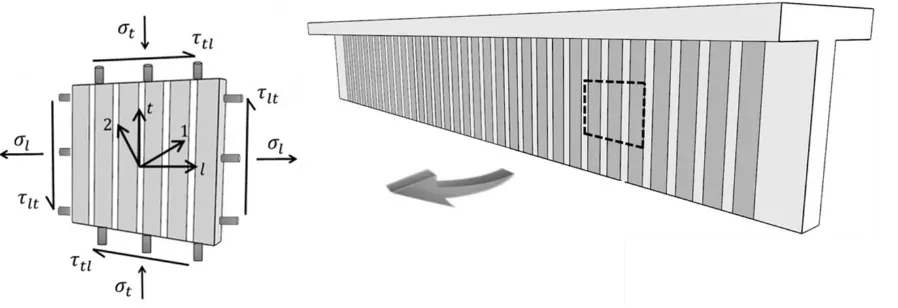
Hsu et al., 1995). As shown in Fig. 1, an element subjected to shear stresses is
separated from a girder strengthened externally by FRP sheets; by taking into
account the inherent characteristics and material laws of the constituents the
behavior of that specific element can be predicted . This will ultimately lead to
understanding the global shear response of the girder . To define the shear behavior
of the element a set of equilibrium equations, compatibility conditions, and
materials laws for steel and FRP reinforcements in the longitudinal l and transverse
t directions as well as the concrete in tension and compression in the principal 1
and 2 directions, respectively are required.
Fig. Error! No text of specified style in document.. Beam Shear Element with In-Plane Stresses (adopted from Yang et al, 2014)
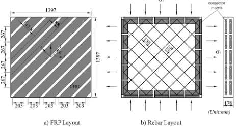
[image:5.612.77.526.479.633.2]5
testing full-size elements (1.398 m × 1.398 m × 0.178 m) as shown in Fig. 2. From the
experimental behavior of representative elements tested in the Panel Tester, new analytical
models can be established. The response of a structure can be predicted by integrating these
analytical models into finite element programs. Following the element-based approach, during
the past decade over 90 panel elements were subjected to monotonic loading to study the shear
behavior of reinforced concrete elements. As a result, three analytical models were developed,
namely: the rotating-angle softened truss model (Belarbi and Hsu, 1994, 1995; Pang and Hsu,
1995), the fixed-angle softened truss model (Pang and Hsu, 1996; Hsu and Zhang 1997), and the
softened membrane model (SMM) (Hsu and Zhu, 2002).
To study the shear behavior of FRP-strengthened RC elements, a total of 10 panel elements
were subjected to pure shear loading. The experimental behavior of such elements will be
presented in a companion paper. A new softened membrane model for FRP-strengthened RC
members (SMM-FRP) was developed from the observed behavior. The SMM-FRP is an
extension of the SMM for RC members.
To expand the use of the SMM to predict the behavior of the FRP -strengthened RC
members subjected to pure shear, new constitutive laws for each material
component of the member , namely, concrete, embedded steel, and externally bonded
FRP, should be established. The material laws of concrete in SMM -FRP includes:
concrete in tension, concrete in compression, and concrete in shear. The material
laws of reinforcements in SMM -FRP includes: steel in tension and FRP in tension.
This paper summarizes the new analytical model by presenting the equilibrium and compatibility
6
the solution algorithm. To further validate the model the comparison of the SMM-FRP
predictions with the test results of 10 panels are presented. . Furthermore, a nonlinear reinforced
concrete finite element program is developed by implementing the SMM-FRP into the finite
element framework OpenSees (McKenna and Fenves 2001). The finite element program is
validated through comparison with experimental results of panel specimens.
[image:7.612.75.540.215.465.2]
Fig. 2. Dimensions of Test Panels
2. Softened Membrane Model for FRP -Strengthened RC Elements
The SMM-FRP satisfies Navier’s three principles of mechanics of materials, namely
(1) the equilibrium equations, (2) the compatibility equations, and (3) the
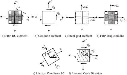
constitutive laws for concrete, steel, and FRP. Fig. 3a shows an FRP -strengthened
RC element subjected to in -plane membrane stresses. This element is based on
superposition of several components, namely concrete element (Fig. 3b), steel grid
7
coordinate systems are used in the SMM -FRP, as shown in Fig. 3e. The l-t
coordinate system represent s the directions of longitudinal and transversal
reinforcements. The s 1-2 coordinate system represents the directions of the
principal compressive stress (2 -axis) and tensile stress (1-axis). In SMM-FRP, the
cracks are assumed to occur along the principal 2-axis. After cracking, the concrete
element is divided into several struts that carry compression stress,
2, in 2-axis, [image:8.612.92.517.288.539.2]also the tension stress,
1, in 1-axis (see Fig. 3e-f).Fig. 3. Stress Diagram for FRP Strengthened RC Element Subjected to In-Plane Stresses (adopted from Hsu and Mo, 2010)
To predict the behavior of the FRP-RC element shown in Fig. 3a, the stress-strain relationships
of concrete, steel, and FRP are required in terms of the principal tensile direction (1-axis) and the
principal compressive direction (2-axis). In the steel element, since no dowel actions are
considered, only constitutive laws of steel in tension (in l and t directions) are required. Similar
8
needed. An FRP-RC element subjected to shear is in the state of biaxial stresses and strains;
therefore, in order to use the uniaxial material laws in the SMM-FRP model, the biaxial strains
have to be transferred into uniaxial strain by involving the Poisson ratio. Once the biaxial
principal strains 1 and 2 along the direction of applied tensile and compressive loads are
evaluated, the Poisson ratios of cracked concrete are required to derive the equivalent uniaxial
strains in 1 and 2 directions.
2.1. Equilibrium and Compatibility Equations
The three equilibrium equ ations (stress transformation equations), which relate the
applied stresses (𝜎𝑙, 𝜎𝑡, and 𝜏𝑡𝑙) to the internal stresses of concrete (𝜎2𝑐, 𝜎1𝑐, and 𝜏12𝑐 ),
steel rebar (𝑓𝑙 and 𝑓𝑡), and FRP sheets (𝑓𝑓𝑡 and 𝑓𝑓𝑙) in a membrane element, are
expressed as
fl fl l l c
c c
l σ α σ α τ α α ρ f ρ f
σ 2 1 12 1 1
2 1 2
1 cos sin 2sin cos (1)
ft ft t t c
c c
t σ α σ α τ α α ρ f ρ f
σ 2 1 12 1 1
2 1 2
1 sin cos 2sin cos (2)
1
2 1 2 12 1 1 2
1 σ sinα cosα cos α sin α
σc c c
lt
. (3)
In Eqns. (1) and (2), in addition to the contributions of concrete and steel, two
additional terms fl ffl and ftfft are incorporated into the original equilibrium
equations of SMM to include the tensile contributions of FRP in the l and t
directions.
The three compatibility equations for FRP -strengthened RC elements are the same
as the equations of RC elements. The compatibility equations which represent the
transformation between the biaxial strains (𝜀𝑙, 𝜀𝑡, and 𝛾𝑙𝑡) in the l-t coordinate
9
in the 1-2 coordinate system along the direction of applied principle stress are gi ven
as follow: 1 1 12 1 2 2 1 2
1 2sin cos
2 sin
cos α α α α
l
(4)
1 1 12 1 2 2 1 2
1 2sin cos
2 cos
sin α α α α
t
(5)
1
2 1 2 12 1 1 2
1 cos sin
2 cos sin
2 α α α α
lt
(6)
The compatibility conditions, defined by Eqns. ( 4-6) contain six variables, namely,
𝜀𝑙, 𝜀𝑡, 𝛾𝑙𝑡, 𝜀1, 𝜀2, and 𝛾12. To solve the three equilibrium and the three compatibi lity
equations,the stress-strain relationships of concrete, steel rebars , and FRP sheets
are required.
2.2. Biaxial Strains vs. Uniaxial Strains
To correlate stresses in the equilibrium formulations to strains in the compatibility
formulations, the stress-strain relationships of concrete , stee and FRP
reinforcements are required. The shear element is in the state of biaxial stress,
therefore, the set of strains used in the compatibility equations given in Eq. (4)
through Eq. (6) are expressed as biax ial strains. The constitutive laws between
stresses and biaxial strains are related to uniaxial strains through the Poisson ratios
of cracked concrete. The Poisson effect has to be considered in the softened
membrane model since all the material laws were developed based on uniaxial tests
(Hsu and Zhu, 2002). In order to use uniaxial material laws in the SMM -FRP model,
10
the Poisson ratio. The relationships between the uni axial strains (𝜀̅1, 𝜀̅2, 𝜀̅𝑙 and 𝜀̅𝑡)
and the biaxial strains (𝜀1, 𝜀2, 𝜀𝑙, and 𝜀𝑡) are given by Zhu (2000) as :
2 21 12 12 1 21 12 1 1 1 1
(7)
2 21 12 1 21 12 21 2 1 1 1
(8)
1 1 12 1 2 2 1 2
1 2sin cos
2 sin
cos
l
(9) 1 1 12 1 2 2 1 2
1 2sin cos
2 cos
sin
t . (10)
Due to the additional bond action created by the externally bonded FRP sheets, the
post cracking Poisson ratios (Hsu/Zhu ratios) are different in case of FRP -
strengthened RC members. In previous research conducted by Yang et al. (2015),
the Hsu/Zhu ratio was found to be affected mainly by the post -yielding stiffness in
the tensile direction. The ratio 𝜌𝑓𝐸𝑓 was chosen as the parameter to describe the
FRP contribution to the post -yielding stiffness. The following equations were
proposed for calculating the Hsu/Zhu ratios 𝜈12 and 𝜈21 in FRP-strengthened RC
members:
sf
k
120.2 when sf y (11a)
f fE
12 1.90.00058 when sf y (11b)
where y f fE k 00058 . 0 7 . 1
(12)
cracking After 0 cracking Before 2 . 0 21
11
where
sf is the average tensile strain along the reinforcements in l and tdirections, whichever yields first.
2.3. Constitutive Relationships of Concrete
In order to use the SMM to predict the behavior of the FRP -strengthened RC
members subjected to pure shear, new constitutive laws for each material
component of the member have to be established. The material laws of concrete in
SMM-FRP includes: concrete in tension, concrete in compression, and concrete in
shear. These materials laws were modified based on the tests results presented in
this research and tests conducted by Yang et el. (2015, 2017).
The ascending and descending branch es of concrete in compression are given by
Eqns. (14a) and (14b).The stress -strain relationship of concrete in compression,
shown in Fig. 4, is given as:
(Stage C1): 2 0 2 0 2 2 2 ε ζ ε ε ζ ε f ζ σ FRP FRP c FRP c
, when 1
0 2 FRP
and (14a)
(Stage C2): 2 0 2 2 1 4 1 1 FRP FRP c FRP c ζ ε f ζ
σ , when 1
0 2 FRP
, (14b)
where,
FRP is the softening coefficient expressed as
f f f
f FRP
f c FRP
FRP
1 (15)
where,
5.8 0.9' ' c c f f
12
, 400 1 1 1 1 f (17)
,16
1
FRP
f (18)
FRP
fEff 10.0076 (in MPa). (19)
A regression analysis of the FRP strengthened RC panels was performed to develop
the new function of the deviation angle, β, in the softening coefficient of FRP
strengthened RC members (Zomorodian, 2015). The ascending and descending
branch of concrete in tension is given by Eqns. (20a) and (20b). The stress-strain
relationship of concrete in tension, shown in Fig. 4, is given as (Yang et al., 2015):
(Stage T1): 1c Ec1 when 1 cr and (20a)
(Stage T2): c cr cr c f 1 1
when 1 cr, where (20b)
s f w
k
k
c
/ , and (21)1
w
K (Fully wrap or U-wrap with anchors), (22)
1.6
w
K (Side bond or U-wrap), (23)
0.25 f f 0.15
f s s E K E
13
Fig. 4. Constitutive Relationships of Concrete
By using the smeared crack theory, the cracked reinforced concrete strengthened
FRP member can be considered as a homogeneous and isotropic material and
therefore assuming that the directions of principle stresses and strains coin cide, the
relationship between the shear stress and strain of cracked concrete in the pricnciple
1-2 coordinate system is derived from equilibrium and compatibility equation s. The
equation relating concrete shear stress, 𝜏12𝑐 , and the concrete shear strain, 𝛾12𝑐 , in the
1-2 coordinate system is given as (Zhu et al., 2001) :
12 2 12 1 12
2
c c
c
(25)
where, 𝜎1𝑐 and 𝜎2𝑐 are calculated from Eq. (20) and Eq. (14), respectively; 𝜀1 and 𝜀2
are biaxial strains in the 1 and 2 directions, respectively.
2.4. Constitutive Relationships of Reinforcements
Two reinforcements are used in FRP -strengthened RC members, namely, steel
rebars and externally bonded FRP sheets. In SMM FRP, the smeared tensile stress
-strain relationships of steel reinforcement embedded in concrete are similar to
SMM. A bilinear expression was proposed by Belarbi and Hsu (1994) to predict the
tensile behavior of steel in RC element . The apparent yielding stress 𝑓𝑦′ was
proposed to describe the reduction of yielding stress. The equations are :
(Stage 1): fs Ess
s
y', (26a)14
(Stage 3):
f
s
f
p
E
s
p
s
s
p (26c)where,
s y
y
f
/
E
'
fy
0.932B
fy (27)5 . 1 1 y cr se f f B
(28)
) ( 75 .
3 f psi
fcr c , and se 0.15% (29)
f s f s
se n
/ , where
s f s f E E
n / (30)
In the above equations, “s” in the subscript of symbols are replaced by l and t for
longitudinal and transversal steel, respectively.
The smeared stress-strain relationship of FRP sheets in the l-t coordinate system is
expressed as:
fs fs
fs E
f fs fu and (31a)
0
fs
f fs fu, (31b)
where Ef s is the Young’s Modulus of Elasticity of the composite, 𝜀̅𝑓 is the average
uniaxial strain of FRP along the fiber direction, and 𝜀𝑓𝑢 is the ultimate strain of FRP
before it ruptures. In the above equations, l replaces s in the subscript of symbols
for the longitudinal FRP, and t replaces s for the transversal FRP.
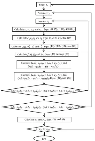
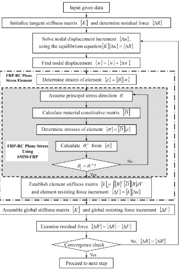
3. SOLUTION ALGORITHM
The solution procedure for the SMM -FRP is provided in Fig. 5. There are a total of
22 variables (𝜀1, 𝜀2, 𝛾12, 𝜀𝑙, 𝜀𝑡, 𝛾𝑙𝑡, 𝜀̅1, 𝜀̅2, 𝜀̅𝑙, 𝜀̅𝑡, 𝜈21, 𝜈12, 𝜎1𝑐, 𝜎2𝑐, 𝜏12𝑐 , 𝜎𝑙, 𝜎𝑡, 𝜏𝑙𝑡, 𝑓𝑙, 𝑓𝑡,
𝑓𝑓𝑙, and 𝑓𝑓𝑡). In pure shear cases, 𝜎𝑙 and 𝜎𝑡 are equal to zero. When a value of 𝜀2 is
15
equations (6 equations for equilibrium and compatibility, 3 for constitutive laws o f
concrete, 2 for constitutive laws of steel in l and t directions, 2 for constitutive laws
of FRP in l and t directions, 4 for relationships relating the strains under uniaxial
loading and strains under biaxial loading, and 2 for Hsu/Zhu ratios). The following
equations are derived from the equilibrium equations, Eq. ( 32) and Eq. (33), to
make the solution procedure more efficient :
c c
t l ft ft t t fl fl l
l f f f f 1 2
(32)
1 2
cos21 212sin21
c c c
t l ft ft t t fl fl l
16
Fig. 5. Flow Chart of Solution Procedure for SMM-FRP
4. Case study of SMM-FRP Calculation Procedure
To illustrate the calculation procedure of SMM-FRP, panel P4-040-FW is taken as an example.
Before calculations, the input data of the specimen are presented in Table 1, which includes the
concrete compressive strength, 𝒇𝒄′, the compressive crushing strain, 𝜺𝟎, the concrete cracking
17
𝒇𝒍𝒚, respectively, the steel ratios 𝝆𝒕 and 𝝆𝒍 in transversal and longitudinal direction, respectively,
[image:18.612.67.540.154.224.2]the steel elastic modulus 𝑬𝒔, the FRP reinforcement ratio 𝝆𝒇, and FRP elastic modulus 𝑬𝒇.
Table 1 Material Properties for Panel P4-040-FW
𝒇𝒄′
(MPa)
𝜺𝟎
(mm/mm)
𝜺𝒄𝒓
(mm/mm) 𝒇𝒍𝒚
(MPa) 𝒇𝒕𝒚
(MPa) 𝝆𝒍 𝝆𝒕 𝝆𝒇
𝑬𝒔
(MPa) 𝑬𝒇
(MPa)
52 0.002 0.00008 462 462 0.00772 0.00772 0.00876 190000 72000
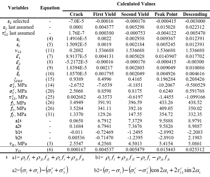
A computer program is written in MATLAB software according to the solution
procedure in Fig. 5. Table 2 gives the calculated results
Table 2 Calculation Results of Panel
Variables Equation Calculated Values
Crack First Yield Second Yield Peak Point Descending
𝜀2 selected - -7.0E-5 -0.00016 -0.000176 -0.000415 -0.003000
𝜀1 last assumed - 0.0001 0.004377 0.005298 0.015028 0.022312
𝜏12𝑐 last assumed - 1.76E-7 0.000380 -0.000753 -0.004122 -0.005470
𝜀𝑙 (4) 1.4916E-5 0.0022 0.002938 0.009367 0.012391
𝜀𝑡 (5) 1.5092E-5 0.0019 0.002184 0.005245 0.012391
𝜈12 (11) 0.2082 1.536688 1.536688 1.536688 1.536688
𝜀̅1 (7) 8.9137E-5 0.004131 0.005028 0.0143907 0.017702
𝜀̅2 (8) -5.2172E-5 -0.00016 -0.000176 -0.000415 -0.00300
𝜀̅𝑙 (9) 1.8394E-5 0.00217 0.002803 0.009049 0.010086
𝜀̅𝑡 (10) 1.8570E-5 0.001795 0.002049 0.004926 0.004616
𝜁𝐹𝑅𝑃 (15) 0.9389 0.4996 0.4165 0.196284 0.208426
𝜎2𝑐, MPa (14) -2.6752 -7.6539 -8.1851 -10.2067 -9.580529
𝜎1𝑐, MPa (20) 2.5068 0.8598 0.8175 0.6240 0.591768
𝜏12𝑐 , MPa (25) 0.002682 -0.3573 -0.6197 -1.4455 -1.099166
𝑓𝑙, MPa (26) 3.4949 391.91 396.59 433.26 438.52
𝑓𝑡, MPa (26) 3.5284 341.11 392.16 409.05 350.02
𝑓𝑓, MPa (31) 1.3370 129.26 147.55 354.72 332.35
a1ǂ - 0.0658 6.7912 7.3729 9.5888 8.9791
a2ǂ - 0.1684 6.7941 7.3676 9.5826 8.9887
b1ǂ - -0.011 -0.72469 -1.2495 -2.8992 -2.2083
b2ǂ - 0.00536 -0.71470 -1.2395 -2.8910 2.1983
𝜏𝑙𝑡, MPa (3) 2.5547 4.2568 4.5013 5.4154 5.0861
𝛾𝑙𝑡 (6) 0.000167 0.004537 0.005479 0.015443 0.025312
ǂ a1=lfl flffl tft ftfft b1= lfl fl ffl t ft ftfft
[image:18.612.96.518.332.689.2]18
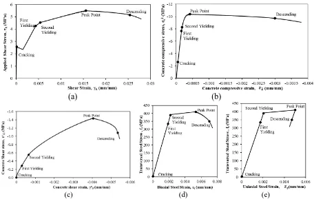
The four points on the curves represent the first yielding point of steel, second
yielding point of steel, peak point, and a typical point in the descending branch,
respectively. In panel P4-040-FW the effective reinforcement ratio in longitudinal
direction was less than the transversal direction, therefore, the first yield point in
the shear stress versus shear strain curve is due to the yielding of the transverse
steel as shown in Fig. 6a. Fig. 6b shows that the concrete compressive stress v ersus
concrete compressive strain curve goes into the descending branch after the
concrete compressive strength reaches the peak point. The concrete shear stress
versus the concrete shear strain curve is shown in Fig. 6c. After the second steel
yields, the slope of the curve decreases up to the peak point. The peak point of the
applied shear stress (Fig. 6a) is accompanied by the peaks of concrete properties in
Fig. 6b and Fig. 6c, indicating that the compressive strength (Fig. 6b) and the shear
strength (Fig. 6c) of the concrete are exhausted. The transversal steel tensile stress
versus biaxial and uniaxial tensile strain curves are shown in Fig. 6d and Fig. 6e,
respectively. In Fig. 6e, it can be observed that the uniaxial steel strain decreases
after the peak point due to stress release from the steel rebars. The strains in the
transversal steel behave in an interesting way after reaching the peak point; while
the uniaxial strain decreases elastically after peak point (Fig. 6e), the Poisson effect
results in the significant increase of the biaxial strain along the descending branch
(Fig.6d). The descending branches are predicted by incorporating the Poisson effect
in the SMM-FRP shown in Fig. 6a, Fig. 6b, and Fig. 6c. While the loading history
of shear stress versus shear strain curve in Fig. 6a moves from the peak point to a
19
longitudinal steel increase rapidly into the strain -hardening region. Beyond the
typical point, the longitudinal and transverse steel stresses decrease.
(a) (b)
(c) (d) (e)
Fig. 6-(a) Applied shear stress ltversus strain ltcurve; (b) concrete
compressive stress c
2
versus shear strain 2curve; (c) concrete shear stress c
12
versus shear strain ltc; (d) transversal steel stress ftversus biaxial steel strain t
curve; and (e) transversal steel stress ft versus uniaxial steel strain tcurve.
5. APPLICATION OF SMM-FRP TO TEST PANELS
A computer program is written according to th e solution procedure in Fig. 5 to
predict the shear behavior of FRP strengthened RC panels . The applied shear
stresses versus shear strain relationships predicted by SMM -FRP are compared with
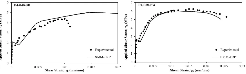
the experimental results of 8 FRP strengthened RC panels . In Fig.7 the experimental
and analytical shear stress-shear strain curves of 8 tested panels in this research are
[image:20.612.72.528.139.428.2]20
The predictions for panel series P3 -FW which were reinforced with longitudinal and
transversal reinforcement ratios of 0.76% and 0.43%, respectively, and strengthened
with FRP fully wrapped along the transversal direction with different FRP
reinforcement ratios as of
f0.54% and
f0.87% for panels 025-FW andP3-040-FW, respectively, are shown in Fig. 7. The analytical results gave conservative
yield strength predictions due to the small steel reinforcement ratios in transvers al
direction. Also, the post crack shear strain was bigger than the experimental results
which lead to a higher prediction in the post crack stiffness. This was due to
neglecting the bond effect between the FRP sheets and concrete substrate which
prevented the cracks from opening and was not considered in the model. The peak
point in these panels where predicted to be higher than the experimental results.
The conservative predictions in the yield strength of panel series P3 -FW are caused
by neglecting the effect of steel ratio on the softening coefficient. This effect was
not taken into consideration as a variable in the softening coefficient for simplicity.
When the steel reinforcement ratio decreases, the concrete struts sustain less stress
and less deterioration, and the concrete contribution increases (Hsu and Zhu, 2002).
Predictions of other panels which had higher steel reinforcement ratios were
satisfactory.
The SMM-FRP model is a smeared model; therefore, the local failure of FRP was
not captured by the model. The model predicted the shear behavior up to the failure
of the strengthening system. For members which failed by concrete crushing rather
than FRP rupture (P4 -080-FW), the behavior especially the descending branch were
21
debonding (P4-040-SB) or anchorage failure (P4 -025-FA) were not modeled
22
Fig. 7. Comparison of SMM-FRP with test results in terms of shear stress-shear strain curves.
6. FINITE ELEMENT FORMULATION OF SMM-FRP
Generally, there are two types of finite element modeling for cracked RC members,
(1) the microscopic models and (2) the macroscopic models (Hsu and Zhang, 1997).
Microscopic models are based on the stress-strain relations of plain concrete and
steel. The interactions of reinforcement and steel through bond slip along the
reinforcing bars and also through shear -sliding along cracked surfaces is the main
focus. Due to the complicated interaction between the components which cannot be
modeled either by the simple superposition of the material laws of plain concrete
and steel, or by the introduction of bond and shear interface elements, the
microscopic modeling is found to be inappropriate for large structures. Therefore,
the macroscopic models were developed to overcome this issue. The macroscopic
approach, also referred to as smeared crack concept is based on the average stress
-strain relationships of concrete and steel where bond slipping an d shear sliding are
implicitly included (Hsu and Zhang, 1997). In this research, a nonlinear reinforced
concrete finite element program is developed by implementing the SMM -FRP into
23
element program is validated through comparison with experimental results of
panels specimens tested in this research. A uniaxial concrete model “ConcreteF01”
and a steel model “SteelF01” are created based on the uniaxial constitutive
relationships of concrete and steel in the SMM -FRP.
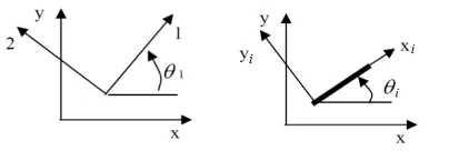
6.1. Coordinate System
In Fig. 8, three Cartesian coordinate systems defined in the reinforced concrete element, x-y, 1-2,
and xi-yi, are shown. The local coordinate of the elements is represented in the x-y coordinate
system. The directions of the principal stresses are defined in the 1-2 coordinate systems and
have an angle
1 with respect to the x-y coordinate system. Furthermore, reinforcing steel barsand FRP sheets can be considered in various directions in the concrete element. Coordinate xi-yi
shows the ‘ith’ direction of the internal and external reinforcements with an angle i with
[image:24.612.206.408.422.490.2]respect to the x-y coordinate system in the direction of axis xi.
Fig. 8. Coordinate systems for FRP strengthened RC elements: (a) applied principal stresses in local coordinate (b) reinforcement component in local coordinate
The stresses and strains are transformed between coordinate systems using
the transformation matrix
T
which is given as
2 2 2 2 2 2 sin cos cos sin cos sin cos sin 2 cos sin cos sin 2 sin cosT (34)
24 6.2. Equilibrium and Compatibility Formulations
The equilibrium equations which relate the applied stresses in the x -y
coordinate ( x, y , and xy ) to the internal concrete stresses in the principle
directions (1c,2c, and 12c ), and also the stresses in the reinforcing bars ( fsi) and
FRP sheets ( ffi) in the directions of the reinforcements a re:
0 0 12 2 1 1 fi fi si si i i c c c xy yx f f
T T
, i=1, 2, 3,…. (35)
where, siand fiare the rebar and FRP reinforcement ratio in the it h direction,
respectively;
T
1
and
T
i
are the transformation matrices from the 1 -2coordinate and the xi-yi coordinate system to the x-y coordinate system,
respectively.
The compatibility equations relate the steel and FRP strains in the xi-yi coordinate
and the concrete strain in the principle 1 -2 coordinate system, expressed as :
12 2 1 1 2 1 2 1 i i i iT (36)
It should be noted that in Eq. ( 36) the reinforcement strains (i) and the principle
concrete strains (
1) are biaxial strains.Biaxial strains are related to uniaxial strains using the Hsu/Zhu ratios (
12,
21)25
transformed to uniaxial strains of concrete (
1 ,
2 ) using the Hsu/Zhu ratios.Afterwards, they are transferred to the uniaxial strains of reinforcements (i) as:
12 2 1 12 2 1 2 1 2 1 V , where (37)
1 0 0 0 1 1 1 0 1 1 1 21 12 21 12 21 21 12 12 21 12 V and (38)
12 2 1 1 2 1 2 1 i i i iT . (39)
The stresses of concrete and reinforcements in Eq. (35) are determined based on the
uniaxial constitutive relationship of the materials.
The stresses and strains of an element are related with a material stiffness
(constitutive) matrix. In the SMM-FRP model, the material stiffness matrix for the
FRP-strengthened reinforced concrete membrane elements are defined in terms of
tangent formulations . The tangent stiffness matrix
D for an FRP-strengthened RC26
xy y x xy y x d d D 2 1and (40)
D
T( 1)
D
V T(1)
T( )
Dri
T(i 1)
V T(1)
i i
c
, (41)
where
Dc is the uniaxial tangential stiffness matrix of concrete;
Dri is theuniaxial tangential stiffness matrix of reinforcements;
V which is defined in Eq.(38) transforms the biaxial strains to uniaxial strains by using the Hsu/Zhu ratios;
T(
1)
is the transformation matrix from the local x -y coordinate to the 1-2coordinate system;
T(
1)
is the transformation matrix from the 1 -2 coordinate tothe x-y coordinate system;
T(i)
is the transformation matrix from the xi-yicoordinate to the x -y coordinate system;
T(i1)
is the transformation matrixfrom the 1-2 coordinate to the xi-yi coordinate system (Hsu and Mo, 2010).
The uniaxial stiffness matrix of concrete
Dc is given as
c c c c c c G E E D 12 2 1 2 2 1 1 0 0 0 0 , (42)
where E1cand c
E2 are the tangential uniaxial modulus of concrete in the 1 and 2
27
diagonal terms
1 2 c and 2 1 c
are obtained by using the uniaxial constitutive
relationships and taking into account the states of the concrete stresses and uniaxial
strains in the 1 and 2 directions.
The uniaxial stiffness matrix of reinforcements
Dri is evaluated as:
0 0 0 0 0 0 0 0 fi fi si si ri E E D , (43)
where Esi and Efi are the uniaxial tangential modulus of rebars and FRP,
respectively, determined for a particular stress/strain state. Dowel action of
reinforcements is neglected since i t is assumed that the FRP and Steel
reinforcement only take axial stresses .
Analysis Procedure of FRP-RC Plane Stress Structures
By using the basic finite element procedure , the tangent element stiffness matrix
K e is evaluated from the tangent material stiffness matrix
D as:
K
B
D
BdVV T
e
, (44)where
B which depends on the assumed displacement function is a matrix thatrepresents the shape function of the element .
To perform nonlinear analysis of RC structures, a n iterative tangent stiffness
method was developed by Zhong (2005). To perform nonlinear anal yses of
28
iterative solution under load control using the Newton-Raphson method. The
procedure for establishment of the material stiffness matrix using SMM -FRP is
shown in the shaded area in Fig. 9. To obtain the material stiffness matrix, since the
principal stress direction is an unknown value, a supplementary iterative loop is
defined for FRP-RC plane stress elements. The method for calculating the stiffness
matrix of FRP-RC plane stress elements are outlined by the outer block shown in
Fig. 9.
The flow chart shown in Fig. 9, presents an analysis method for FRP-RC plane
stress elements using load control. It should be noted that other integrators such as
displacement control can be incorporated in the model . The incremental equilibrium
29
Fig. 9. Nonlinear Finite Element Analysis Algorithm (adopted from Zhong, 2005)
Convergence criterion is required to conclude if convergence has been achieved at
30
6.3. Implementation of the nonlinear finite element program
New material classes related to FRP -strengthened RC membrane elements are
implemented into the OpenSees framework to perform analysis on FRP
-strengthened RC plane stress structures Two uniaxial material models for concrete
and steel in FRP-strengthened RC, namely ConcreteF01 and SteelF01 are created
and implemented into OpenSees based on the ConcreteZ01 and SteelZ01 material
models developed by Zhong (2005). The material model of ConcreteF01 needs five
input parameters: the ultimate compressive strength fc, the compressive strain0
corresponding to fc, FRP reinforcement ratio
f , FRP Young’s modulusEf , and theparameter “c” of concrete in tension,. An object of SteelF01 needs the following
parameters: yield stress fy, Young’s modulus Es, concrete compressive strength fc,
and effective steel reinforcement ratio se.
A 2D material class named “FRPRCPlaneStress”, which is a class for FRP
-strengthened RC plane stress material using SMM -FRP, is created and implemented
into OpenSees. In FRPRCPlaneStress, the stress vector is calculated. Furthermore,
an object of FRPRCPlaneStress material needs the tags of the newly created
uniaxial steel and concrete objects of SteelF01 and ConcreteF01, , the steel ratio for
the steel in each direction, the directions of the steel reinforcement, concrete
compressive strength, steel Young’s modulus, steel yield stress, FRP reinforcement
ratio, and FRP Young’s modulus. Two uniaxial concrete objects are needed in
defining one FRPRCPlaneStress object, which represents the concrete in the two
31
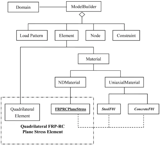
In Fig. 10, the implementation of the FRPRCPlaneSt ress into OpenSees is shown.
The FRPRCPlaneStress is executed with a Quadrilateral element which represents
the FRP-RC plane stress elements. The FRPRCPlaneStress is related with
ConcreteF0l and SteelF0l to determine the tangent stiffness matrix and to calculate
element stresses.
The FRPRCPlaneStress will collect the strains of the elements in each trial,
calculate the uniaxial strains of the reinforcements and concrete, then the concrete
uniaxial strains and the perpendicular tensile strains are refered to the two
previously defined concrete material objects. Furthermore, the concrete object will
then calculate the stiffness matrix and corresponding stresses and transmit the
values to the FRPRCPlaneStress object. Likewise, FRPRCPlaneStress will send the
uniaxial strains of the steel to the uniaxial steel object and receive the stress and the
tangent stiffness from the uniaxial steel objects.
The tangent stiffness matrix will be calculated and the stress vectors will be
evaluated After receiving the uniax ial stress and stiffness of concrete, steel, and
FRP materials. As shown in Fig. 9, an iterative procedure is defined to obtain the
converged material stiffness matrix and stress vector for a given strain vector.
The user can define the degree of freedom o f the node which controls the the
solution. The displacement increment for each path of the displacement scheme can
vary. To resolve numerical issues in the nonlinear analysis, the size of
32
Fig. 10. Finite Element Implementation of SMM-FRP (adopted from Zhong, 2005)
The FRPRCPlaneStress material is implemented with the quadrilateral element in
OpenSees, which constructs a four-node quadrilateral element object to represent
the FRP-RC plane stress four node elements. The four node quadrilateral element
object uses a bilinear isoparametric formulation. It should be noted that a standard
isoparametric element faces many limitations such as shear locking were the
displacement values could be smaller than expected. When the element is subjected
to pure bending the term shear locking used to define the development of shear
stresses.
6.4. Simulation of FRP-strengthened RC panels
In this section, the developed nonlinear finite element program is verified by the
experimental results of FRP strengthened RC panels under monotonic shear. The
33
shown in Fig. 11a. The panels were reinforced with different steel and FRP
reinforcement ratios.
Since the material properties and stress conditions were uniform throughout all the
panels, they were modeled using one 2 -D FRP-RC element as shown in Fig. 11b. The
boundary conditions and loading scenario are defined to mimic the pure shear
loading on the panel elements. In Fig. 12, the predicted panel responses are
[image:34.612.160.449.278.581.2]compared to the experimental .
34
Fig. 11b Finite Element Mesh of Panel Specimens
As shown in Fig. 12, the predicted results of most of the panels for the whole
loading history agree very well with the experimental results. The post cracking
shear strain and the descending branches of panels REF -P3 and P3-FW series did
not match well with the experimental results. This can be due to the low steel
reinforcement ratios in the transversal direction in these panels. The post crack
shear strain was bigger than the experimental results which lead to a higher
prediction in the post crack stiffness. This was due t o neglecting the bond effect
between the FRP sheets and concrete substrate which prevented the cracks from
opening and was not considered in the model. The predictions of panels which had
higher steel reinforcement ratios were satisfactory. Panel P4 -040-SB failed by
debonding of FRP sheets from concrete substrate, therefore the finite element
prediction was satisfactory for this panel only up to failure. The behavior of panel
P4-080-FW which had the highest FRP reinforcement ratio was predicted very well
35
mode has a great impact on the predictions. For panel P4-080-FW, since it failed by
concrete crushing rather than FRP rupture, the behavior especially the descending
branch, was modeled accurately. Other panels which failed by FRP rupture,
debonding or anchorage failure were not modeled accurately in the ir descending
branch.
The SMM-FRP is a smeared model; therefore, the local failure such as debonding of
FRP and spalling of concrete was not captured by the model. Furthermore,
bond-sliping and shear sliding was not considered in the model ; however, they are
implicitly included. The model predicted the shear behavior up to the failure of the
strengthening system. Moreover, the proposed SMM-FRP model is a
two-dimensional model under plane stress conditions. These could be considered as the
36
Fig. 12 Comparison of Experimental and Finite Element Analysis of Panels
The comparison of shear stress and shear strain curves between the experimental
panel tests and two different SMM finite element analyses of panels P4 -040-FW and
P4-040-FW are shown in Fig. 13. One is the SMM with the original constitutive
laws of concrete and steel in tension for RC members with just the addition of the
FRP reinforcements in the equilibrium equations. The other one is the SMM -FRP
which includes all the new interacting material models for concrete, steel, and FRP.
It can be seen that the origin al model underestimated the tension stiffening effect of
37
better prediction. The new softening equations and also the new Poisson’s ratio
resulted in a better prediction of the b ehavior, especially in the descending portion
of the curves.
a) Panel P4-040-FW b) Panel P4-080-FW
Fig. 13 Comparison of SMM and SMM-FRP Finite Element models of Panels
CONCLUSIONS
In this study, an analytical model (SMM-FRP) is proposed to predict the full shear behavior of
FRP strengthened RC members. The SMM-FRP is an extension of the SMM. By using an
iterative solution algorithm, the equilibrium equations, compatibility equations and the new
constitutive relationships of materials deduced in this study are combined to calculate the
unknown variables. The main conclusions are as follows:
1. The comparison between the theoretical values calculated by SMM-FRP and the
experimental results of 10 panels indicates a good prediction for the overall shear
behavior of the FRP strengthened RC members, including pre-cracking and post-cracking
behavior.
2. More reasonable compressive and tensile constitutive relationships of FRP strengthened
RC members subjected to shear loading that take into account the effect of externally
38
3. It was observed that the original SMM model underestimated the tension stiffening effect
of concrete for FRP strengthened RC members, while the SMM-FRP model with
modified constitutive laws and the new softening equations and Poisson’s ratios resulted
in a better prediction of the behavior, especially in the descending portion of the shear
stress-strain relationship.
ACKNOWLEDGMENTS
The authors would like to acknowledge the financial support provided by the National Science
Foundation (NSF), award number 1100930. Steel reinforcements and FRP materials were a
donation from Gerdau Ameristeel Co. and FYFE. Co, respectively. Their support is greatly
acknowledged.
Nomenclature
The following symbols are used in this paper:
B factor for calculating apparent yielding stress
c coefficient for tension stiffening
c
E modulus of elasticity of concrete
c
E1
tangent uniaxial modulus of concrete in 1-direction
c
E2 tangent uniaxial modulus of concrete in 2-direction
f
E
tensile modulus of elasticity of FRPfi
E tangent uniaxial modulus of elasticity of FRP in ithdirection
s
E modulus of elasticity of steel
' c
f
specified compressive strength of concretecr
39
fe
f
effective stress in FRPfi
f stress FRP sheets in the ith direction
fl
f smeared (average) stress in FRP in l-direction
ft
f smeared (average) stress in FRP in t-direction
l
f smeared (average) stress in embedded mild steel rebars in l-direction
ly
f yield stress of mild steel rebars in l-direction
s
f smeared (average) stress in embedded mild steel rebars
si
f stress of steel rebars in the ith direction
t
f smeared (average) stress in embedded mild steel rebars in t-direction
ty
f specified yield strength of steel rebars reinforcement in t-direction
u
f specified ultimate tensile strength of steel reinforcement
,
u FRP
f
ultimate tensile strength of FRP sheety
f
specified yield strength for reinforcement'
y
f
apparent yield stress of steel rebarc
G12 shear modulus of concrete in 1-2 coordinate
k factor considering the wrapping scheme effect in crack spacing
1
k bond coefficient
2
k loading coefficient
/ f s
K
factor for FRP/steel stiffness ratiow
K factor for wrapping scheme
l direction of longitudinal steel bars
40 /
f s
n
ratio of Young’s Modulus between FRP and steelt direction of transverse steel bars
i
t local coordinate of steel layer in ith direction where tiis the direction
perpendicular to the steel layer
s
t direction of transverse steel bars
x local coordinate of RC/FRPRC element
y local coordinate of RC/FRPRC element
angle of transverse reinforcement relative to the longitudinal axis
F
orientation angle of the fibers with respect to longitudinal axisβ deviation angle
1
ε
change of strain in principal 1-direction
2
ε
change of strain in principal 2-direction
0
concrete cylinder strain corresponding to peak cylinder strength '
c
f
1
ε smeared (average) tensile strain in principal 1-direction
ε₂ smeared (average) tensile strain in principal 1-direction
cr
cracking tensile strain of concrete
ε
f strain in FRPε
fe effective strain in FRPε
fu design rupture of FRP reinforcementl
smeared (average) strain of steel bars in l-direction
ε
sf smeared (average) strain of steel rebars that yield firstt
41 '
εy strain corresponding to apparent yield strength of steel reinforcement in SMM
1
smeared (average) strain in 1-direction when panel is subjected to
uniaxial loading
2
smeared (average) strain in 2-direction when panel is subjected to
uniaxial loading
l
smeared (average) strain of steel rebar in l-direction when Hsu/Zhu ratios are assumed to be zero
s
strain in mild steel, s becomes l and t , when applied to the
longitudinal and transverse steel, respectively.
t
smeared (average) strain of steel rebar in t-direction when Hsu/Zhu ratios are assumed to be zero
12
smeared (average) shear strain in 1-2 coordinatec
12
smeared (average) concrete shear strain in 1-2 coordinate
120
smeared (average) shear strain in 1-2 coordinate at maximum shear stress
lt
smeared (average) shear strain in l-t coordinate
12
Hsu/Zhu ratio (ratio of resulting tensile strain to source compressive strain)
21
Hsu/Zhu ratio (ratio of resulting compressive strain to source tensile strain)
angle of diagonal compressionf
FRP reinforcement ratio
fl
FRP reinforcement ratio in l-directionft
FRP reinforcement ratio in t-directionse
equivalent reinforcement ratio
l
42 s
ratio of steel reinforcement
t
steel reinforcement ratio in t-direction
1
smeared (average) tensile stress in principal 1-direction
c
1
smeared (average) tensile stress of concrete in principal 1-direction
2
smeared (average) compressive stress in principal 2-directionc
2
smeared (average) compressive stress of concrete in principal 2-direction
σf smeared (average) tensile stress in FRP sheet
l
smeared (average) tensile stress in l-direction
c l
stress resisted by concrete in l-direction
t
smeared (average) tensile stress in t-direction
c t
stress resisted by concrete in t-direction
lt
smeared (average) applied shear stress in l-t coordinate
c
12
smeared (average) concrete contribution to shear stress in 1-2coordinate
c lt
smeared (average) concrete contribution to shear stress in l-t coordinate
FRP
softening coefficient considering FRP sheet
B matrix representing the shape function of the element
D tangent material stiffness matrix
Dc uniaxial tangential stiffness matrix of concrete
Dri uniaxial tangential stiffness matrix of reinforcements
K e element stiffness matrix
K global stiffness matrix
43
V Hsu/Zhu matrix
f element resisting force increment vector
F global resisting force increment vector
R , R residual force vector
u nodal displacement vector
u nodal displacement increment vector
applied strain vector of the plane stress element
applied stress vector of the plane stress elementREFERENCES
Belarbi, A. (1991). Stress-strain relationships of reinforced concrete in biaxial tension-compression (Doctoral dissertation). Department of Civil and Environmental Engineering, University of Houston, Houston, TX.
Belarbi, A., & Hsu, T. T. C. (1994). Constitutive laws of concrete in tension and reinforcing bars stiffened by concrete. ACI Structural Journal, 91(4), 465-474.
Belarbi, A., & Hsu, T. T. C. (1995). Constitutive laws of softened concrete in biaxial tension compression. ACI Structural Journal, 92(5), 562-573.
Bousselham A., and Chaallal O. (2008). Mechanisms of shear resistance of concrete beams strengthened in shear with externally bonded FRP. Journal of Composite for Constructions, 12(5), 499-512.
Chen G. M., Teng J. G., & Chen J. F. (2010). Interaction between steel stirrups and shear-strengthening FRP strips in RC Beams. Journal of Composite for Constructions, 14(5), 498-509.
Hsu, T. T. C. & Mo. Y. L. (2010). Unified theory of concrete structures. West Sussex, UK: John Wiley and Sons Ltd.
Hsu, T. T. C., & Zhang, L. X. (1997). Nonlinear analysis of membrane elements by Fixed-Angle Softened-Truss Model. Structural Journal of the American Concrete Institute, 94(5), 483-492.
Hsu, T.T.C., & Zhu, R. R. H. (2002). Softened membrane model for reinforced concrete elements in shear. Structural Journal of the American Concrete Institute, 99(4), 460-469.
Hsu, T.T.C., & Zhu, R. R. H. (2002). Softened membrane model for reinforced concrete elements in shear. Structural Journal of the American Concrete Institute, 99(4), 460-469. Hsu, T.T.C., Zhang, L.X. & Gomez, T. (1995). A servo-control system for universal panel tester.
Journal of Testing and Evaluations (ASTM), 23 (6). 424-430.
McKenna, F. & Fenves, G. L. (2002). The OpenSees command language primer. University of California, Berkeley, CA.