1
Titanium Microalloyed steels
T.N. Baker
Metallurgy and Engineering Materials Research Group,
Department of Mechanical and Aerospace Engineering, University of Strathclyde, Glasgow, G1 1XJ.
[ T. N. Baker (2018) Titanium microalloyed steels, Ironmaking & Steelmaking, DOI: 10.1080/03019233.2018.1446496]
Abstract
For many years titanium has been regarded as a relative minor element in microalloyed steels compared with niobium and vanadium. However, over the past decade or so, titanium compounds in microalloyed steels have been recognized as having a wider role than just involved in austenite grain refinement.This is considered in the present review.
The background and brief history are followed by sections dealing with the physical state of titanium and compounds of titanium, including borides, carbides, nitrides, oxides and sulphides characterized in MA steels. Many of the investigations on the solubility of these compounds in iron, and the precipitates they form, are considered, which leads to their functions in controlling the mechanical and toughness properties of MA steels.This now often involves the multiple alloying additions of titanium, niobium and vanadium with both carbon and nitrogen, and the morphologies of the various precipitates characterized in MA steels is presented. Titanium has become an important element in the development of line pipe steels, which for the higher grades have moved to bainite/acicular ferrite microstructures. The influence of Ti in the nucleation of acicular ferrite is an active research area, particularly with regard to the use made of titanium compounds in welding of MA steels. Finally, consideration is given to the influence of titanium on hot ductility and how titanium additions behave during continuious casting and thin slab direct charging processes.
2
Introduction
Microalloyed (MA) steels, also known as High Strength Low Alloy (HSLA) steels, have become an indispensable class for a range of applications such as in the construction of large ships, oil and gas transmission lines, offshore oil drilling platforms, pressure vessels, building construction, bridges, storage tanks and automomotives. In 1997, F.B. Pickering 1 published what was probably the first review of titanium MA steels. In the intervening years, much has been written on the effect of titanium in low carbon steels, as additions of titanium, often with niobium and or vanadium have become more common practice, particularly in steels for linepipe
applications.The present review attempts to fill the gap mentioned by Cochrane2in a wide
ranging review of ‘phase transformations in microalloyed high strength low alloy (HSLA) steels’ through the consolidation of many of the pertinent publications considering titanium in MA steels. It follows the format used by the author in previous reviews which dealt with the role of vanadium 3and with zirconium 4 in MA steels. Parts of the present review were also discussed in
an invited review on Microalloyed Steels. 5
Titanium and its alloys have many applications in the aerospace, petrochemical energy producing industries and in prosthetic devices. Titanium, which weighs forty percent less than carbon steels, can be strengthened by alloying with elements such as aluminum and vanadium. 6, 7The most
widely used titanium alloy, Ti-6Al-4V, is present in forty-five percent of titanium alloy industrial applications. The unique combination of this alloy's physical and mechanical properties with workability, fabricability, production experience and commercial availability allows it to be economically useful.8, 9However, only five percent of the titanium mined today is used in its
metallic form. Some of the remainder is used to manufacture titanium dioxide (TiO2), an
3 0.02% were known to reduce segregation of carbon, sulphur and phosphorus in rail steels as long ago as 1914, 10, 11 and by 1921 it was being used as an alloying element in steel.12Table 1, taken
from Baker4 andMorrison, 12 lists data on the main microalloying additions, and it is noticeable
that titanium was the earliest, and niobium the most recent. An examination of the literature shows that nearly all the elements now used as deliberate additions in MA steels were used in low alloy and stainless steels for what was described as precipitation strengthening, but was thought to be due to the precipitation of intermetallics such as Ni3Ti and TiSi.11To achieve this, larger
additions were made than in current MA steels.Initially, the role of titanium added to steel as ferro-titanium, was mainly to reduce grain size and as a deoxidizer. Small additions of titanium, <0.05wt.% can improve the strength of steel, and this was first exploited in Germany in l92l. Micro titanium and micro vanadium additions began to be used in China in the l950s and l960s. At this time, it is noticeable that whereas carbides and nitrides of some transition metals were known to form and considered to be responsible for grain refining, the idea that they could also precipitate in ferrite and induce significant dispersion strengthening does not appear to have been accepted until after the work of Morrison and Woodhead 13,14circa 1962. This study on niobium
steels showed that in the as-rolled state, if the strengthening due to the inherent lattice
strengthening (the friction stress) together with the grain boundary strengthening was subtracted from the measured lower yield stress, a significant degree of strengthening remained still to be accounted for, which was shown to coincide with the formation of niobium carbide. A further very important aspect of this work, was that it was the first to apply the ideas proposed by Hall 15
and Petch 16 to account for the relationships found in mild steel between grain size and yield
stress, and by Petch 17,18 for that between grain size and the ductile-brittle impact transition
4 The term microalloying as applied to steels, is generally accepted as emanating from the additions of transition metals to commercial heats of a carbon steel. However the major event that initiated the HSLA Steel revolution did not occur until 1958 when the Great Lakes Steel
Corporation of the USA began production of low C Mn steels microalloyed with niobium.19 This
event created widespread interest among the world's steelmakers leading to the rapid deve1opment of HSLA Steels containing the additions of microalloying elements vanadium, niobium and titanium either singly or in combinations. In particular, titanium additions are known to give effective grain size control in HSLA steels at high temperatures in the austenite temperature range
20,dispersion strengthening and sulphide shape control, all leading to improving the strength and
toughness. Also, the properties of strip and plate steel products, such as cold formability and toughness anisotropy, are significantly improved by titanium additions, the latter also being important in welding metallurgy. 21
Pickering1 noted ‘that among the elements normally considered as those which constitute
microalloying additions in HSLA steels, that is Nb, Ti, V, Zr and possibly Al, titanium is the most unique and versatile due to its strong affinity for C,N,S and O. This feature is not displayed by the other microalloying elements which often show strong affinities for one or more of the above elements, but not all of them’. However, because titanium is a strong deoxidizer, additions are only fully effective in fully killed, (aluminium deoxidized) steels, so that titanium is available for forming compounds other than titanium dioxide. 22 The importance of titanium in microlloyed
steels is summarized succinctly by Jönsson.23 ‘Titanium has a very strong affinity for carbon and
5 transformation characteristics of the steel and lead to the superior mechanical properties of
microalloyed steels.’
Background
Titanium, (Ti), atomic number 22, atomic weight 47, density 4.506g.cm−3 , is a lustrous transition
metal with a silver, greyshire colour, low density and high strength. It is as strong as steel but 45 percent lighter, and it is twice as strong as aluminium but only 60 percent heavier. It is highly resistant to corrosion in sea water, aqua regia and chlorine.24
Titanium was discovered in Cornwall, UK, by the British clergyman and amateur geologist William Gregor in 1791, who produced a white metallic oxide from black magnetic sands. Titanium dioxide (TiO2) has a very high refractive index, which means that it has high
light-scattering ability. As a result, TiO2 imparts whiteness, opacity, and brightness to many products. In
1795, the German chemist Martin Heinrich Klaproth named the oxide “titanium” after the Greek Titans, a mythical race of immortal giants with incredible strength and stamina.
Titanium has not been found in the free state in nature and always bonded to other elements. It is the ninth-most abundant element in the Earth's crust (0.63% by mass) and the seventh-most abundant metal. It is present in most igneous rocks and in sediments derived from them (as well as in living things and natural bodies of water). Of the 801 types of igneous rocks analyzed by the United States Geological Survey, 784 contained titanium. Its proportion in soils is approximately 0.5 to 1.5%. It is a metal resembling tin in its chemical properties, and like tin, is capable of forming oxides, TiO and TiO2.Only the latter occurs in nature; it supplies an example of
trimorphism, constituting the three minerals, rutile, anatase and brookite. Titanium oxide also enters into the composition of ilmenite, the oxide of titanium and iron, FeO.TiO2. Many samples of
6 time, ilmenite and rutile are the chief sources of the titanium required in industry. Titanium also occurs in a number of rock forming silicates, the chief of which is sphene or titanite, CaTiSiO5.
Most of the exploited minerals, however, are of detrital character, such as beach-sands. The annual world production of titanium minerals has increased from 50,000 tons in 1947 to 6.8 million tons in 2013. Currently, the chief producers of ilmenite and rutile are Australia (19.4%), South
Africa(17.3%) ,Canada (10.4%) India 8.6%), Mozambique (7.7%), China (7.5%) Vietnam(7.3%) and Ukraine (5.3%).25
Pure titanium metal was first isolated in 1910 by chemist Matthew Hunter. Hunter’s difficult isolation process made titanium metal mainly a laboratory curiosity until 1938 when William Kroll developed a method (known as the Kroll method) to produce titanium metal in commercial
quantities. 6, 26,27
A more recently developed method, the FFC Cambridge process, may eventually replace the Kroll process.28 If mixed oxide powders are used, the product is an alloy manufactured at a much lower
cost than the conventional multi-step melting Kroll process. The FFC Cambridge process may render titanium a less rare and expensive material for the aerospace industry and the luxury goods market, and could be seen in many products currently manufactured using aluminum and specialist grades of steel.
Narita 29 has assembled data on the recovery of the elements in Groups IVA and VA, which are
reproduced in Table 2.
Table 2 near here
Titanium bearing steelmaking additions range from titanium metal to Ti alloys containing 83-99% Ti to ferrotitanium containing 70% Ti with some 4.5% Al and 3%V.1
Titanium: the physical state
7 is hexagonal close packed and stable up to 882ºC, while beta, which is body centred cubic, is stable between 882ºC and the melting point,1668 ± 2ºC. The specific heat of the alpha form increases dramatically as it is heated to this transition temperature, but then falls and remains fairly constant for the beta form, regardless of temperature.6, 30 The relationship between titanium and other
elements,which are in Groups IVA, VA and VIA, is given in Table 3.31
Table 3 near here
The properties of titanium, zirconium and iron have been compared by Schwope.32 These metals
all possess allotropic transformations and they form solid solutions with each other if the size factors of the metallic elements are favourable, and the formation of continuous solid solutions has been observed in most of these systems. 33
Table 4 near here
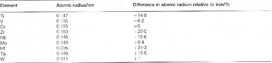
Table 4 shows the atomic radii of many of the transitions elements and their difference from iron.31Here it can be seen that while the vanadium atom radius has the smallest difference
compared to the iron atom, zirconium and hafnium have the largest difference, with titanium midway.
A summary of their allotropic transformation and the influence on the number of outer electrons on the stability of carbides and nitrides was given by Baker. 4 Andrews and Hughes 34 have
8
Compounds characterized and reported based on titanium additions to MA
steels.
Borides
Boron additions to titanium MA steels forming TiB2 have been shown to have beneficial effects
on the weld metal toughness. 35 Munroe 36has collected and critically reviewed the material
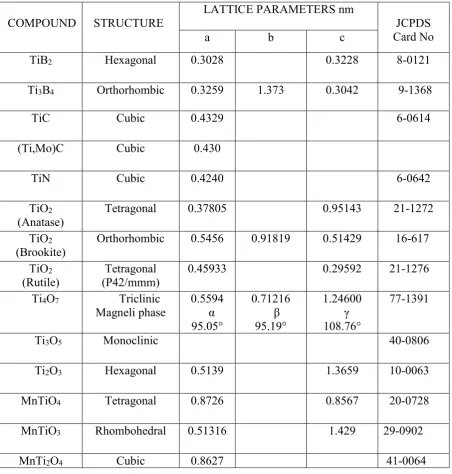
properties of titanium diboride. The crystallographic data are similar to that given in Table 5. TiB2
is not normally found in MA steels, but has been characterized in high speed steels. 37It has also
been used for cladding of low carbon steels using laser surface engineering. The high surface hardness was attributed to a composite of TiB2 10-20 µm long needles within an equiaxed
dendritic matrix of iron.38
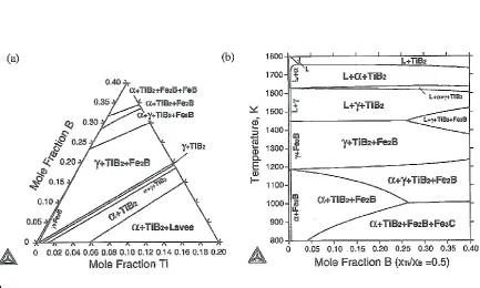
Ohtani et al. 39 have calculated the Fe-Ti-B ternary system which has also been investigated
in part by Tanaka and Saito.40 The Fe-rich portion of an isothermal section of the Fe-Ti-B ternary
phase diagram at 1273K is shown in Figs.1a and 1b
Figs.1ab. near here
Here TiB2 is in equilibrium with Fe containing between 0 and 5.5 at% Ti which is applicable to
MA steels The system has been up-dated by Raghavan 41 and recently by Antoni-Zdziobek et
al.42 Much of the current interest in the Fe-Ti-B system is due to the development of high
strength, high modulus MMC steels containing 10-20 vol.% of TiB2,These are of particular
interest to the automotive industry, 42,43 but out-with the scope of MA steels. Little is available on
more complex systems containing C and N, except to note that in the Fe-Ti-B-C system, increasing C leads to the formation of TiC in addition to FeB2.41
9 Titanium, zirconium and hafnium [M], which in the periodic table are elements near the
beginning of the long periods, form very stable MC carbides, but the affinity for carbon
diminishes further along the rows of the periodic table. With M carbides, the metal has to sacrifice four electrons to form the bonds with carbon. Titanium has exactly the right number, so that on forming TiC, its d-orbitals are left empty.
Table 5 near here
Titanium carbide, TiC, and titanium nitride TiN, both fcc compounds, Table 5, are the most commonly noted titanium precipitates in MA steels. Since the 1970’s, TiC, TiN and their complexes with Nb and V, have been the subject of more thermodynamic modelling than other transition metal carbonitrides.23 In the size rage 1-100nm, they are known to provide Orowan
dispersion strengthening.44,45The complex compounds based on TiC-TiN in the presence of Nb
and V are considered in the following section.
While titanium carbonitrides have been characterized on several occasions, the presence of an iron borocarbide, Fe23 (B, C)6 , was identifiedin a Ti-B weld by Oh et al.46
Oxides
The study of the oxides of titanium is a subject in its own right. Titanium exists in several oxidation states, Ti2+, Ti3+ and Ti4+,and the oxides,Ti
nO2n-1(n=4-10),known as the Magnéli
phases,appear in the following order, going from the surface to the bulk of TiO being oxidized: TiO2–Ti10O19–Ti9O17–Ti8O15–Ti7O13–Ti6O11–Ti5O9–Ti4O7–Ti3O5–Ti2O3–TiO. These are shown
in Fig. 2, an O-Ti equilibrium diagram based on Murray and Wreidt.47
Fig.2 Near here
Many titanium oxides have important applications arising from their magnetic and electronic properties, and also as catalysts and in pharmaceutics and paints. Furthermore, they are
10 than aluminum, magnesium or calcium,as seen in Fig.3,which shows a plot of the free energy ,ΔG vs temperature T,K, of oxides including titanium,present in steels.
Figure 3 Near here
Much of the research on titanium oxides in steel has been concerned with their behavior in the region of 1600°C as slags, before quenching to ambient for identification.48,49 Mutale et al. 50
using TEM/ SAED, have identified six forms of titanium oxide from individual inclusions in liquid steel at 1600 °C. Because of structural similarities, it is established that a series of solid solutions based on TiC, TiN and TiO, with a general formula of TiCx Ny Oz .(0 ≤ x, y, z ≤
1,+x+z=1), can form. 49 However, these complex compounds, as far as is known, have not been
identified in steel. Titanium-iron oxides have been identified in steel by Cha et al 49, and as seen
in Fig.4, forms several complex compounds.
Figure 4 Near here
Sulphides
The Ti-S phase diagram has been studied extensively through empirical techniques 51,52 and
modelling. 53 In Fig. 5, the equilibrium diagrams published prior to 1986, collated by Murray, 52
show a number of phases between Ti6S and TiS2.
Figure 5 Near here
Raghaven 54 andBochvar and Rokhlin 55 have collected information on the ternary systems
based on Fe-S, including Fe-S-Ti. The titanium sulphide phases identified in steels are shown in
Table 5.The most common titanium sulphide constituent of microalloyed, maraging and
interstitial free (IF) titanium bearing steels is Ti4C2S2 .It has been suggested that this compound
11 Oikawa et al. 57 have established a thermodynamic database forthe Fe-Cr-Mn-Ni-Ti-S-C-N
system, with the specific aim of predicting the precipitation behaviour of sulphides and
carbosulphides in titanium containing IF steels. In particular, they have examined critically, data onTi4C2S2 and TiS phases which they consider have significant influence on both texture and
mechanical properties of IF steels. Kudielka and Rohde 58 were the first to identifyTi
4C2S2 and it
has been characterized by many since 1960, mainly in IF steels.
Hua et al. 59,60 made a distinction between IF steels, C ≈ 0.003, and dilute MA steels, C
0.04%-0.08%, but considered that titanium sulphides did not normally precipitate in MA steels.
However, this distinction did not follow in the steels containing 0.05%-0.075% C with 0.05% to 0.25%Ti and 0.01%S,investigated by Liu et al.61Their extensive research collected data and
micrographs using analytical TEM and SEM, and showed in Fig.6, that while the %C influenced the % Ti4C2S2, this compound should form in Ti-MA steels.
In several instances, Ti4C2S2 particleswere observed by Hua et al.59,60 to be surrounded by MnS.
MnS stringer inclusions rich in Mn, S and Ti were found in the 005%-0.18%Ti steels, while in the 0.25%Ti steel, globular sulphides, with no detectable Mn, were observed. 59Iron was not
identified in any of the inclusions. Liu et al.. 61 concluded that the optimum level of titanium
required to form a globular sulphide inclusion in a 1.5%Mn steel,was around five to six times that necessary to tie up the N as TiN.
Figure 6 Near
Earlier work by Bandi and Krapf, 62 studying 0.13C steels containing 0.053-0.13 Ti,
found Ti4C2S2 in all their steels.. However, they were unable to distinguish between Ti4C2S2
and τ Ti2S by x-ray diffraction, but using differential thermal analysis-evolved gas analysis
procedures, they considered there was some evidence for the presence of τ Ti2S in one of their
12 Ti4C2S2 was also identified in IF ultra- low carbon Ti-stabilized and semi-stabilized cold –rolled
sheet steels, widely used for automotive bodies.61 , 63Mizui et al. 63 found that the solubilities of
both Ti4C2S2 and TiS in IF steels increased with Mn content, equations (13) and ( 13a), and that
Ti4C2S2 was more stable than TiS between 950 and 1250°C. The crystal structure of titanium
sulphides was re- examined by Ball.64 He critically compared the data of τ Ti
2S, JCPDS data file
(11-664), and suggested that this compound may have been confused with Ti4C2S2. Ball64
concluded that τTi2S did not exist in steels and had it been confused due to additional lines
appearing in some X-ray diffraction patterns.
It has been pointed out by Wilson and Chen, 65 that ten intermediate phases the Ti-S system have
been identified, 63, 64 making it particularly complicated. One method considered as a means of
lowering the volume fraction of MnS in steels, and hence improving toughness, was by reducing the Mn content to <0.3%.This approach was investigated by Wilson and Chen 65 who made a
comparison of the effect of a Ti-free steel with one containing an 0.01% Ti addition, (lower than any addition studied by Liu et al., 61 on the sulphides identified in 0.06C-
0.3Mn-0.017Nb-0.011S-0.003N steels. Their specimens were heated to 1350°C, held for 1min, cooled at 200°C min-1to the testing temperature of 800 or 900°C, where they were strained to fracture at 1x10⁻³s-1,
then water quenched to room temperature, all using a Gleeble simulator.Analytical TEM /SAED showed that the most numerous sulphide identified in both steels was manganese
–iron-sulphide, either as 50-400nm globules or as rods, ≤7 µm long by 0.2 µm wide. In the Ti containing steel, smaller iron titanium sulphides were found, Figs. 7(a) and 7(b). The large rod precipitates were considered to remain undissolved at 1350°C,65while iron titanium sulphides
were likely to be a mixture of TiS,Fe1-xS and NbS,which could be written as (Fe,Ti,Nb)S.
Figures 7(a) and 7(b) near here
The SAED patterns collected by Wilson and Chen 65 indexed as an hexagonal structure with
13
Table 5. Hexagonal structures of TiS were not found in this study. 65
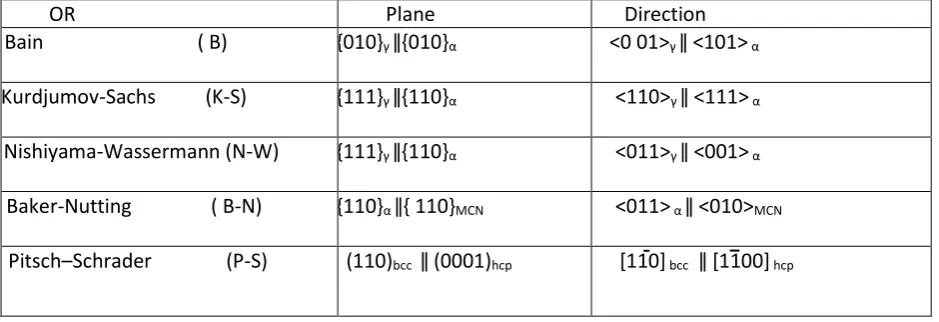
Some of the main orientation relationships (OR) found between phases in MA steel are collected in Table 6.
Table 6. near here
Solubility of titanium compounds in iron
Prior to the roughing rolling sequence, the soaking temperature of the steel must be sufficient to take into solution the microalloying compounds. In MA steels, the most important particles are carbides and nitrides, often present as carbonitrides of the transition metals, niobium, titanium, vanadium, and to a considerably lesser extent, zirconium. In certain cases, oxides of titanium and sulphides are of importance, as are aluminium nitride precipitates. During processing, the lowest temperature for taking into solution the particles precipitated on casting, which are later to control grain size and dispersion strengthening, is determined by their solubility in iron as a function of temperature and time. Matlock and Speer 66 considered that the main precipitates were likely to
be based on NbC, V(C,N) or TiN. In particular, solute niobium, remaining in solution in austenite, may also contribute to subsequent formation of nano- precipitates or clusters 67- 74and finer
dispersion strengthening precipitates in ferrite. Recently, Kapoor et al. 75 using atom probe
tomography (APT), have characterised GP –zone like clusters corresponding to (Ti, Nb)C, along with (Ti,Nb)(C,N) nano-precipitate in Nb-Ti steels.
TiN is very stable and usually precipitates at high temperatures in the austenite phase and may resist subsequent austenite grain coarsening, when added as a small addition. The basis for most of the conclusions made by Matlock and Speer 66 lay with the solubility equations associated with
iron phases appropriate for carbides and nitrides of niobium, titanium and vanadium in austenite. These equations developed for binary compounds, are also the source for the more complex alloys, such as (Nb, Ti, V)(C, N, Va),where Va is the vacancy concentration in non-equilibrium
14 Solubility equations allowing the temperature of compounds in a solvent to be estimated,
for example, titanium carbide in austenite,76 are normally described in the form of an
Arrhenius equation. This gives the dependence of the rate constant K of chemical reactions on the temperature T (in absolute temperature, kelvins) and activation energy Ea, as shown below
K=A- Ea /RT (1)
where A is the pre-exponential factor and R is the Universal gas constant.
In microalloyed steels, the microalloying element, M is often combined with an interstitial X, to give a compound, MX, some or all of which, dissolves in austenite as the temperature is raised.
[M]+[X] =MX] (2)
The rate constant K in equation (1) is now described as an equilibrium constant for the reaction given by equation (2). In practice, the concentrations of M and X are normally low, being less than 1% and therefore may be considered as having an ideal solution behaviour. M and X are expressed in terms of the weight percentage of the alloying element present in the steel chemical composition. This allows equation (1) to be expressed as
log10 [M][X] =Kx= -Q1/RT +C J mole=1 (3)
and putting Q1/R =Q, gives:
log10 kx =C- Q/T (4)
15 Empirical Arrhenius equations have been determined for many of the important refractory
carbides and nitrides known to form in steels, but similar equations for sulphides are less common. Table (7), summarizes selected Q and C values, collated from the literature, for the relevant grain boundary pinning and dispersion hardening compounds found in steels containing titanium additions.
The solubility equations of the binary compounds in iron of the transition metals combined with carbon and nitrogen, form the basis for investigating the phase relations in higher order systems such as Fe-Nb-V-Ti-C-N. Improvements in this data have been continually sought and been attained since the 1970’s.
The solubility of titanium carbide and titanium nitride in iron has been the subject of many
investigations, based on both experimental data and thermodynamic modelling. Much of what was published prior to the year 2000 has been considered by Jonsson 23 and by Dumitrescu and
Hillert.77 The latter based parts of their own thermodynamic analysis on that undertaken by
Jonsson.23 They collated data for C and Q of equation (4), which is reproduced in Table (7). Lines
of best fit are shown in Figure 8. Figure 8 and Table 7 near here
The solubility constants for TiC in γ considered by Dumitrescu and Hillert 77 include those
determined by Balasubramanian et al. 78 at 1273K and 1473K, and by Ohtani et al. 79 at
1273,1373 and 1473K.They do not include data by used by Gladman,80 taken from Mori et al., 81 whose values of C, 5.12 and Q, 10300, are in also good agreement with those of Ohtani et al. 79
16 There have been many investigations into the solubility of TiN in iron, the main studies being associated primarily with the liquid phase, with the precipitation of TiN during melting, casting and rolling, and then in austenite, usually concerning grain refining.82,83 Kunze et al. 84 provided critical summaries of the iron phase, through considering the importance firstly of dissolution and secondly the experimental methods employed, including their short comings. This provides what they regarded as the best solubility equations for TiN in the four phases of iron, liquid-l, delta δ, austenite-γ, ferrite-α.These are included below, along with results from other work.
Liquid iron:
Turkdogan 85 considered the work of Frage et al 86, Morita and Kunisada 87and Evans and Pehlke, 88 in arriving at :
logl0 ([%Ti][%N]) = -17040/T +6.4 (6)
This equation gave an almost identical solubility product at 1873K to that obtained by a thermodynamic analysis conducted by Ohtani and Hillert.89 Kim et al.90 considered that errors were introduced by selecting interaction parameters obtained by different experimental techniques and taken from several sources. 88,91 They investigated this system using metal-nitride- gas equilibration under different nitrogen partial pressures. The results of Kim et al.90 were consolidated into the most recent theoretical work on the solubility of TiN in liquid iron, carried out by Jang et al.,92 over the temperature range 1823 to 1973 K, resulting in
equation (7),
logl0 ([%Ti][%N])= -12740/T +4.06 (7)
17 was determined by the Sieverts’ method, excellent agreement is obtained. However, at 1923K and 1973K, the curves predicted in the work of Morita and Kunisada 87 are higher than those of Kim et al. 90 and Jang et al.92 This was considered by the latter 92to result from the location of the thermocouple used to measure the melt temperature: at the bottom of the crucible,87 compared with immersion.92 Figure 9d shows the kl data at 1903K and 1953K measured by Ishii and Fuwa, 94which are in excellent agreement with the curve calculated by Jang et al.92Furthermore, equations (6) and (7) agree well at the lower two temperatures, but deviate at 1923K. At 1973K, considering a melt containing 0.3%Ti and 0.016%N, gives kJl of 4.8 x10⁻³, while equation (6) gives kTl of 5.8 x10⁻³.This latter value lies much closer to the
full line in Fig 9d, representing the solubility products given by the calculations of Jang et al.,92than any of the curves above it, suggesting that there is little to choose between the
equations (6) and (7) for the temperature range considered here. Fig 9 near here
Delta ferrite:
The solubility equation of titanium nitride in delta ferrite was revised by Kunze et al. 84from the earlier measured version by Kunze 95 of log k
δ = -15490/T +5.19 to equation(8):
[logδ ([%Ti][%N]) = -17205/T +5.56 (8)
derived from experimental measurements within the temperature range 1693-1783K. Kunze et al. 84 noted that the equation obtained by Ohtani and Hillert, 89based on a
thermodynamic analysis, gave solubilities which were lower by a factor of 2 than their own experimentally determined solubilities.
Austenite:
18 which may arise from the choice of experimental method, and Dumitrescu and Hillert,77 who
discussed the choice of data available in the literature necessary for a thermodynamic analytical approach. A reassessment undertaken by Dumitrescu and Hillert 77 on the solubility of TiN in iron was based on the C and Q data collated in Table 8 which compare quite well with their calculated estimates. Dumitrescu and Hillert 77 do not mention the detailed correlations made by Kunze et al., 84who included some different sources.
Table 8 near here Fig 10 near here
The solid line in Fig.10 is from calculations made by Dumitrescu and Hillert,77while the
dashed and dotted lines are from the survey made by Jönsson.23 The calculated line 77 in Fig.10 falls well below the experimentally determined data of Kunze for TiN in γ.96
The dashed line in Fig.11 is the same as the solid line in Fig.10 from Dumitrescu and Hillert.77 This lies reasonably close to that determined from the experimental approach taken by Kunze et al., 84 showing a particularly good correlation for the solubility of TiN in γ over a wide
temperature range. The assessment by Kunze et al. 84 which considered much of the earlier data, concluded that, ‘owing to the large scattering, only an order of magnitude of TiN solubility in austenite can be recognized. However, a temperature dependence described by the term -15000/T is highly probable.’ Further experiments reported by Kunze et al. 84 involved zone melting in a carburizing atmosphere, to obtain a distribution coefficient of a component, here titanium, which is the relation between its concentrations in solidus and in the liquidus.
Fig 11 near here
This enabled Kunze et al. 84 to derive equation (9,
19 logγ ([%Ti] [%N]) = -15490/T +5.19 (10)
Alpha ferrite
Equation (8) is considered by Kunze et al. 84 to hold for TiN solubility in both α and δ ferrite. More complex systems have been considered in an attempt to predict the effect of the interaction of multi- elements in MA steels on the solubility of compounds characterised experimentally, and to allow quantitative determination of their concentrations.
Gorbachev and Popov 97have considered the Fe-Ti-C, Fe-Ti-N, and Fe-Ti-C-N systems. Their main conclusion was that ‘the thermodynamic calculations show that under equilibrium conditions in the austenite region of steels alloyed with titanium, only cubic carbonitrides can form. If the amount of titanium in the steel is greater than that of nitrogen, the influence of carbon becomes more noticeable.’ They also mention the possible formation of an
intermetallic hexagonal Laves phase based on Fe2Ti,which, in the case of the Fe-Ti-C system,
can precipitate from bcc α solid solution. It would appear that this phase is very unlikely to be present in MA steels. This is due to the amount of titanium required to form the Laves phase, which depends linearly on the content of the carbon in the steel. The solubility of titanium carbide in ferrite is considerably less than the solubility of the Laves phase. Titanium therefore combines preferentially with carbon, and only the remainder not capable of being dissolved in ferrite, is left to form the Laves phase. This explanation applies equally to the Fe-Ti-N system.
20 critical point. Non-uniform compositions within precipitate particles of MA steels, considered to be due to phase separation within the particles, were found experimentally by Zhou and
Kirkaldy.99, 100. As noted by Rudy101 and by Inoue et al.,102 ‘phase separation occurs in precipitates depending on the difference of thermodynamics of terminal components in the (M1,M2)(X1,X2) double pseudo-binary system’. Here M1 and M2 are transition metals while
X1and X2 , carbon and nitrogen.
For detailed information on the thermodynamic modelling of complex carbonitride formation of the system Fe-Nb-Ti-C-N, the work of both Lee 103 and of Gorbachev et al.104 should be consulted, and for Fe-V-Ti-C-N, that of Gorbachev et al.105Their critical examination of the available data for both of these systems provides a good source for theearlier work in this field. Inoue et al.102 was perhaps the first to attempt a thermodynamic description of the system
Fe-V-Nb-Ti-C-N. This was a calculation of the phase equilibria between austenite and
(Nb,Ti,V)(C,N) in MA steels, based on the Gibbs free energy of each phase being described by two sub-lattices. These required evaluations of the solubility products, K, formation energies and interaction parameters, L, of each carbide and nitride. For fcc compounds, a linear relationship has been shown to hold between the lattice constant and the mole fraction.98,101 Inoue et al.102 equated Lfcc to the compositional average of the lattice constants of the two terminal
components, ā ,and the difference from the average, Δa, through the equation:
L fcc = 6.03x10⁶ (Δa / ā)2 (Jmole=1) (11)
and listed the Lfcc and K data used for each carbide and nitride. However, more recent data for K
is considered in detail below. Inoue et al.102 concluded that the carbonitride separates into TiN and NbC, whereasV tends to dissolve into the nitride.
21 An examination undertaken by Liu 106 involved a detail comparison of calculated compositions of the carbonitrides expected in the (Ti,Nb)(C,N) system with experimental data published by Craven et al. 107 In their work on multicomponent Ti Nb MA steels,107with the compositions given in Table 9, some (TixNb1-x)NyCz carbonitride particles consisted of multiple caps in the
form of epitaxial overgrowths on a core as seen in Fig.12. Fig.12 near here
Using parallel electron energy loss spectroscopy (PEELS), Craven et al. 107obtained the amount
of both metallic elements and carbon and nitrogen, showing that the N/(Ti + Nb) atomic ratio in the core was similar to the average value in the steel, whereas the Nb/Ti ratio was much smaller than that in steel. The composition in the cap changed from Nb(C, N) to (Nb,Ti)C as the N/Ti ratio in steels decreased.
Table 9 near here
Using the steel compositions given in Table 9,the thermodynamic calculations of Liu,106,based on a three miscibility gap formulation, indicated that the precipitates formed above 1400°C are Ti and N rich, whereas those nucleated around 1100°C, are Nb and C rich. The calculated particle compositions 106 are given in Tables 10 and 11, together with calculated values of Frisk,108which were also considered to be in reasonable agreement with the experimental data of Craven et al.107 An excellent summary of previous thermodynamic modelling for iron multicomponent Nb, Ti, and V carbides and carbonitrides, is given by Frisk,108 extending that of Jonsson.23 Frisk108 calculated data based on the application of a CALPHAD approach to consider the
22
Tables10 and11,show a reasonable comparison with the experimental data of Craven et al., 107 many somewhat closer than the calculations made by Liu.106
Tables 10 and 11 near here
Frisk and Borggren109 have recently extended the earlier model to consider the
Fe-Cr-Nb-Mo-C-N system. Experimental data was obtained to study the phase separation into V-rich and Nb- V-rich carbides/carbonitrides, and allow comparison with the calculated data. They concluded that ‘the types of precipitates were correctly predicted by the calculations in all cases, and the compositions well reproduced. Xu, Thomas and O'Malley 110 have presented
a computational model of equilibrium precipitation of 18 different oxides, sulphides, nitrides and carbides and 13 different elements in MA steels.The model is based on satisfying
solubility limits including Wagner interaction between elements, mutual solubility between precipitates, and mass conservation of alloying elements. It predicts the compositions and amounts of stable precipitates for multicomponent microalloyed steels in liquid, ferrite and austenite phases at any temperature. These calculations were validated by those of
commercial packages, and predicted the evolution of precipitates in two commercial steels containing Nb-Ti-V additions, which also agree with the experimental data of Craven et al.107
More recently, Xu, Tang and Song 111 proposed a simpler theoretical model to predict complex equilibrium precipitation in Nb–Ti–V bearing microalloyed steels. It is assumed that the complex precipitate with B1 type consists of six kinds of binary compound, namely, NbC, NbN, TiC, TiN, VC, and VN. The authors note that their predictions agree well with other recent research.
Roy et al. 112modelled the effect of segregation on the stability of microalloy precipitates and
on the size distributions at different regions (solute rich and solute depleted), an area which is not well understood. They compared of two as-cast slabs:
23 (B) 0.07C-1.20Mn-0.-034Al-0.041Ti. The nitrogen level was not given.
In slab (A), cuboidal TiN, cruciform and cuboidal (Nb, Ti) (C, N), and spherical NbC and VC precipitates which had the greatest volume fraction, were characterised, and varied with position in the slab. TiN precipitates, with various morphologies and sizes, were found in slab (B). The model112 proposed for micro-segregation, which was a feature of the slab
microstructure, gave a satisfactory agreement between experimental observations and
predictions for precipitate size distribution and the amount of precipitates in the interdendritic and dendrite centre regions of segregated slabs. It was concluded that this type of model may help,
(i) to avoid hot cracking,
(ii) in the selection of soaking time and temperature and predicting austenite grain size during soaking and
(iii) in designing the rolling schedule for achieving maximum benefit from the microalloying precipitates.113
It is of interest to note that by using data from many of the papers referred to above, Raghavan114 has up-dated the phase diagrams of the C-Fe-N-Nb-Ti system.
Sulphur in low carbon steels is normally present as MnS, and over the years, the effects of the various morphologies have been the subject of much research. 115,116 In steels with additions of titanium, titanium sulphide, sometimes containing iron, and / or titanium carbosulphide, are both frequently reported.58-65The solubility of TiS in γ-iron was probably first investigated by Swisher 117 who determined the solubility product as: log γ [Ti%][S%]=-17,640/T +8.20 (12) More recently, Mizui et al. 63assessed the solubility products of TiS and Ti
4C2S2 in
24 that the presence of MnS has an influence on the solubility of TiS, and included a manganese term in equation (13):
logγ[Ti%]2/3 [S%] = - 0.021-5847/T- (3.360-5 195/T . [Mn%] (13) where they describe TiS as Ti2S3, to account for the presence of iron in this compound, which
showed an atomic ratio, Ti /S of 2/3 in their steels.
Equation 13a was deduced for Ti4C2S2 in γ-iron.63
logγ[Ti][C]1/2[S]1/2 =0.392-7004/T-(4.783-7401/T). [Mn] (13a) Among the beneficial effects in strip and plate steel products resulting from additions of
titanium, are improvements in cold formability and toughness anisotropy. This has been attributed to the formation of titanium carbosulphide (Ti4C2S2, sometimes written as Ti2C2S), which
remains undeformed during hot rolling, due to its high hardness at elevated temperatures.116 The solubility product of Ti4C2S2 in γ was determined by Liu et al. 61 and described by
equation (14):
Kγ= logγ[Ti%][C%]0.5[S%]0.5= -15,600/T +6.5 (14) Ti4C2S2 has often been reported as the main sulphide in IF (0.005%C) steels compared with
MA (0.05%C) steels. Using equation (14) to calculate Kγ, it is evident in Fig.6, that the solubility of Ti4C2S2 in γ is significantly greater in IF steels, resulting in more solute Ti and S available to
form TiS.
The solubility product for manganese sulphide in γ-iron is given by Turkdogan et al.118 as; ks =[Mn%] [S%] fs Mn (15)
log ks = -9020/T +2.93 (16) log fs Mn [(-215/T +0.097 ][%Mn] in γ) (17)
Here fs Mn expresses the effect of manganese on the activity coefficient of sulphur in austenite(). Fig 13 near here
25 that for many titanium-free MA steels, containing ≥1%Mn, most of the sulphur is combined as MnS. Liu et al.61 compared in Fig.14, the temperature dependence of K
γ in γ of Ti4C2S2 with the
other most likely compounds to precipitate in titanium steels. It can be seen clearly that Kγ of
MnS, TiS and Ti4C2S2 lie between the values of TiC and TiN.
Fig 14 near here
Precipitation of titanium compounds in microalloyed steels
The precipitation of carbides, nitrides and carbonitrides, regarded as the main class of particles influencing mechanical properties and toughness in MA steels, is described by Lui and Jonas 119 as occurring at three different stages during the thermomechanical processing (TMP) routes. Type 1 precipitates are formed in the liquid phase and during or after solidification for the duration of casting, on the liquid/solid interface or in delta ferrite. These precipitates, or inclusions as they are often described, are very stable, and while they are normally too large to influence recrystallization of austenite, the smallest may effectively retard coarsening of austenite grains during reheating or during a welding cycle. Type 11 precipitates nucleate in austenite after solution treatment and during hot deformation, such as controlled rolling, as the temperature is decreasing. A pre-precipitation grouping of atoms, known as Guinier–Preston(GP) zones in non-ferrous alloys and also described as ‘clusters’, has received increased attention over the past decade due to the development of atom probe tomography (APT).These clusters grow to what is sometimes described as nano-precipitates. Following TMP, the precipitates are usually strain induced, (SIP); that is nucleated on dislocations and can retard the recovery and recrystallization of austenite. Grain refinement of MA steels associated with TMP is mainly due to this group of particles, which have been shown to coarsen during cooling through the austenite phase.
Finally, type 111 particles are formed during or after the austenite to ferrite phase transformation, nucleating on the austenite/ferrite interface and in ferrite. Through these changes, a fine
26 resulting in dispersion strengthening in ferrite, also known as precipitation hardening. Ardell120
makes a distinction between these two forms of strengthening.
Several of these precipitate nucleation processes have been recognised in MA steels. These include homogeneous precipitation, resulting in coherent precipitates with strain fields, leading to semi-coherent and incoherent precipitates, interphase precipitation, heterogeneous precipitation on grain boundaries and dislocations.
Titanium oxides 49and titanium nitride 92,121,122have been characterised as type 1 particles, in both MA welded and in as cast steels. Type 11 particles observed after solidification, can take the form of dendrites, Fig.15, or in the case of TiN, a cube shape, Fig.16. Particles in this category also nucleate on prior grain boundaries and fall into a smaller size group than those in Figs. 17 and 18.
Figs15 and 16 near here
Figs 17 and 18 near here
In controlled rolled MA steels, much attention has been paid to the combination of additions of titanium and vanadium, titanium and niobium or titanium and niobium with
vanadium, the expectation being that the potential of each element will be fully exploited. Most of the work discussed below emphasises that titanium additions are normally made as
hypostoichiometric relative to nitrogen, i.e. < 1:3.4. This ratio is discussed by Crowther and Morrison, 124 who explained the influence that titanium additions were observed to have in Al– V and Al–Nb MA steels, particularly with regard to loss of strength. This was purported to be due to changes in the dispersion strengthening associated with modifications to niobium precipitates. However, the individual levels of Ti and N are perhaps the main factors which result in TiN precipitating in the liquid phase as type 1 particles.
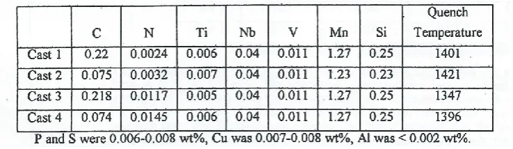
Chen et al. 125 studied Nb-Ti and Nb-V-Ti steels, with the aim of assessing the thermal stability of large precipitates formed during continuous casting. Their two experimental steels had the following compositions:
27 Nb-V-Ti steel 0.082C-1.32 Mn-0.030Al-0.0076N-0.039Nb-0.019Ti-0.057V Ti/N=2.53 Three particle morphologies were noted in the as cast samples. In the Nb-V-Ti steel, cuboidal TiN particles, with the same morphology as in Fig.16, but these >0.5µm, type 1 particles, were considered to nucleate in the liquid phase, due to the concentrations of titanium and nitrogen in the steel. The authors believed that type 1 precipitates should be avoided, as they have no advantageous effect on the steels properties, removing both Ti and Nb, which would otherwise form smaller precipitates capable of grain refining or dispersion strengthening, as later confirmed by He and Baker.126
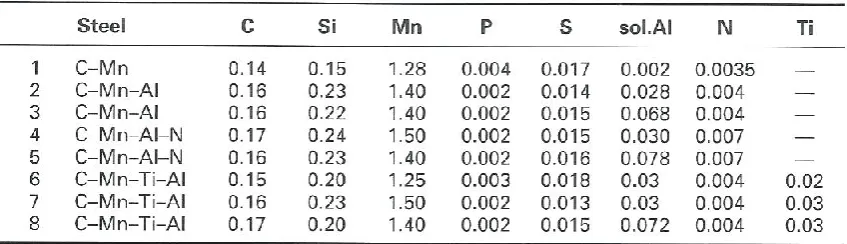
Secondly, type 11, TiN- rich (Ti,Nb)(C,N) dendritic precipitates up to 10µm long , were recorded in the Nb-V-Ti steel and NbC–rich in (Ti,Nb)(C,N) dendritic precipitates in the Nb-Ti steel. Thirdly, dendritic precipitates nucleating on (Ti, Nb) N during the final stage of solidification of the interdendritic liquid or on δ-phase boundaries and growing in the solid state. EELS spectra indicated that they were nitrides with a Ti core and a Nb-rich skin. This sequence of precipitate chemistry and morphology was, in the main, found to hold by Li et al 127 who compared
experimental observations made by TEM/EDX/PEELS techniques on MA steels having two carbon levels and two nitrogen levels, shown in Table 12, with a thermodynamic model for processing thin slab direct rolled (TSDR). The Ti/N ratios for each cast were 2.5, 2.18,0.43 and 5.10.
Table 12 near here
After solidification, the casts were quenched from 1400ºC to investigate eutectic
28 experiments, new precipitates, Nb rich at low and intermediate temperatures (1300ºC) and V rich at low temperatures(800ºC), were observed. The particles became more cuboidal at high reheating temperatures. After holding for 24hrs at 1200ºC, TiN particles in cast 4, Table 12, were found to be pure nitrides, but above this temperature, TiMnO tended to supplant TiN. In low N cast3 steel, co-precipitation of oxide and nitride, sometimes with MnS, was observed. However, the
flower/cruciform precipitates or the coatings of Nb(C, N) observed by Baker et al 128, were not reported by Li et al 127 or by Yuan and Laing 129.Unfortunately, the latter did not provide the composition of their forged Ti/Nb MA steels, which were isothermally held at 1300ºC for up to 48hrs,before water quenching. After forging, they observed two kinds of type11 (Ti,Nb)(C,N) precipitates,
cuboidal 50 -100nm Ti rich, with Ti/Nb ratios initially of 6:1,increasing to 15:1 after 48hrs,and
10- < 5nm spherical, Nb-rich carbonitrides.
The former were considered to precipitate on solidification, while the later were SIP in austenite during the forging process. From their analytical TEM/SAED/EDX data, they argued that the original large precipitates were nucleated with complex monophase TiNb compositions, rather than TiN particles, which then acted as nucleation sites for Nb(C,N),as found in previous work. The first stages of precipitation in ferrite of type 111 carbonitride particles in TMP MA steels involves SIP with some interphase precipitation, or in heat-treated steels, interphase precipitation followed by homogeneous precipitation.
29 The initial stages of nucleation of particles in steels has intrigued scientists for decades,
particularly when nitrogen was involved. K. H. Jack 131 proposed that homogenous precipitation of carbides, nitrides and carbonitrides in ferrite in heat treated steels followed a sequence analogous to that occurring during the ageing of Al-4%Cu alloy, commencing with GP zones. That is: homogeneous solid solution, GP zones- mixed substitutional - interstitial solute clusters, coherent, semi-coherent, and finally incoherent precipitates. He pointed out that GP zones are metastable and have a higher solubility than the equilibrium precipitate. The high supersaturation was regarded as the driving force for clustering. Early evidence, by Kirkwood et al 132, for this sequence was detected following nitriding of Fe-3%Ti alloys, which developed a microstructure with tetragonal distortion of the ferrite lattice by nitrogen, and coherency between the matrix and thin plates on {100}α planes. Initially this was identified as clustering or zone formation, through
streaking in 200α reflections of the matrix diffraction patterns, being replaced by streaking through 110 MCN precipitate reflections, which occurred after annealing at 850° C, when softening
was noted. The microstructure was described as having a ‘tweed’ appearance. TiN plates were identified lying on {100 α planes with a Bain orientation relationship with the matrix, Table 6.
The streaking disappeared when the precipitates lost coherency. This precipitation sequence for the Fe-Ti-N system was fully described by D.H.Jack.133 He also estimated the thickness of the zones from streaking in SAED patterns. The zones comprised two planes of iron atoms together with a Ti-N plane, giving a three layer stack, with two 0.194nm interplanar spacings. No
evidence of dislocation formation accompanying the development of the coherent plates was reported.
Cuddy et al, 134 studying the elevated temperature strengthening of iron alloys, found
30 suggested that ‘this effect was due to the presence in the lattice of stable clusters of titanium and carbon or nitrogen atoms, which reorient in the stress field of mobile dislocations, thereby
impeding their motion.’ At this time, the authors were unable to characterize the particles in their specimens, to provide support for their ideas.
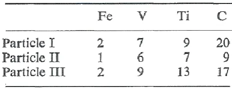
The atom probe, (AP), was used by Dunlop and Turner 135 to determine the chemical composition of carbides precipitated in a low alloy steel containing two strong carbide forming elements, V and Ti, which, as mentioned above 33, develop isostructural carbides with an NaCl- type crystal structure. A vacuum melted model steel, Fe-0.08C-0.18V-0.13Ti, was solution treated at 1300ºC, water quenched, followed by isothermal transformation at 725ºC or 800ºC. Characterisation of the precipitates, present predominantly as interphase precipitation, was undertaken by TEM and AP analysis in a field ion microscope ( FIM). Typically, 25-30 atoms were analysed for each particle, and Table 13 shows data for three particles, ~6nm in size. The data show a mixed transition metal composition, including iron as part of the precipitate. The iron disappeared on subsequent ageing. However, clustering of atoms prior to nucleation of precipitates, was not dealt with.
Table 13 near here
Dunlop and Honeycombe 136 extended this work,135 through the study of Fe-0.08C-0.40V and
Fe-0.09C-0.33Ti model steels. Using dark field TEM, they compared the high- temperature coarsening behaviour of interphase precipitates of VC, TiC and (V, Ti)C particles in ferrite, It was found that TiC interphase dispersions initially coarsened most rapidly, while (V,Ti)C coarsened the least rapidly. The identification of clusters through the presence of streaking in SAED patterns is fully discussed by Chechenin et al,137 who used a variety of techniques to examine precipitate formation in nitride FeNiTi films, which supported many of the ideas mentioned above,
31 Kostryzhev et al. 71 studied the strengthening sources following TMP, in a commercial steel containing 0.08C-0.064Nb- 0.021Ti and 0.0047N. Analytical SEM and AP was used to
characterize and size atom clusters and precipitates. Two size groups of particles were identified, <70nm and >70nm.All particles in the < 70nm range, for all the TMP schedules used, were Ti-free, and were mainly NbC. The APT study revealed Nb- containing solute atom clusters and very fine precipitates, with diameters in the range 3-13nm. No clusters containing Ti atoms were recorded. The particles >70nm had various morphologies and compositions, being cuboidal (Ti,Nb)(C,N),ellipsoidal Nb (C,N) or ellipsoidal NbC.
Problems associated with the quantitative analysis of Ti(C,N) using APT, based on a model Ti (C0.7 N0.3) material,were considered in detail by Angseryd et al.139 The method they proposed to
deal with the inaccuracies associated with carbon data was shown to provide a similar analysis to PEELS, but without the problems due to surface oxidation. Their method was applied by Kapoor et al.,75 who followed the precipitation sequence from the core to the surface of particles in two steels, whose base composition is given in Table 14. Alloy 1, a high-Ti 750MPa steel, containing Ti-rich (Ti,Nb)(C,N) and Ti-rich(Ti,Nb)C precipitates, was compared with Alloy 2,a high-Nb, 580MPa steel containing Ti-rich (Ti,Nb)(C,N)precipitates and (Ti,Nb)C clusters. These
embryonic precipitates were smaller than the (Ti, Nb)C precipitates in Alloy1, being only a few atomic layers thick, with a chemical analysis of 33.8± 8C-38.4±10Ti-27.8±6.8Nb(at.pct).The absence of clusters in Alloy 1 was considered to be due to the Ti addition being twice that of Alloy 2.
Table 14 near here
There are several reports of clusters of Nb atoms in Nb containing steels, 68-75 while clusters of TiO ,140TiOC141 and (Ti,Mo)C142 in steels have been noted. APT was used to generate
analyses of solute clusters and precipitates in an 0.04C-1.52Mn-0.21Si-0.08Ti-0.22Mo steel
32 Fig 19 near here
The AP data revealed the coexistence of nanoclusters and precipitate particles, even after
isothermal holding for 3600 s. The size of the nanoclusters and the precipitates was expressed as
a Guinier radius, associated with the small angle scattering technique, which lay between 0.5
and 8 nm, with the average size ∼1.8 nm, for two strain conditions, ε = 0 or 1. The composition
of the nanoclusters and precipitates varied over a wide range, comprising a mixture of Ti and
Mo, mostly rich in C. The average precipitate composition was close to that of MC carbide
stoichiometry, where M represents a mixture of Ti and Mo. In most cases, the Ti/Mo ratio in the
MC carbides was > 1. As the Guinier radius exceeded 2.5 nm, the composition range became
narrower towards the MC carbide stoichiometry, including a small amount of Fe (∼3–12 at.%).
These microstructural features occurred both within 3-D interphase precipitate sheets,
considered more fully in the next section, and in randomly selected fields of view. It was
observed that the interphase row spacing of precipitates was reduced with the application of a
pre-strain. A bimodal distribution of larger precipitates (∼8–10 nm) coexisted with smaller
nanoclusters (∼3 nm) within the interphase sheets/rows. Both the nanoclusters and the
precipitates had a disc morphology, although nanoclusters with less than ∼30 atoms were
found to be more irregular in shape. Recently Mukherjee et al.143 have extended their earlier
work to obtain a fundamental understanding of interphase precipitation during an isothermal
hold at 650°C, up to100 hrs. A steel of lower Ti, containing
33 carbonitride precipitates nucleated at a high temperature, were rich in Ti and N, but lean in C. As the temperature decreased, successive Ti(C, N) precipitate layers nucleated on the TiN rich cores, followed by layers richer in C and leaner in N. Nb then started to precipitate, to give (Ti,Nb)(C,N) in the outer particle layers. Eventually, when N was exhausted from the matrix, a second set of precipitates, (Ti,Nb)C rich in Nb, nucleated homogeneously, on lattice defects or on existing carbonitrides. These sequences are illustrated in Fig.20, taken from Kapoor et al., 75 and agree in part with similar experimental precipitate compositional data collected by Baker et al.128 using PEELS with EDX, and Shanmugam et al.144 Similar observations were recorded by Li et al.145 investigating the precipitate evolution in a TMP microalloyed steel containing 0.09C-0.025Nb-0.03V-0.011Ti-0.0037N. SEM, TEM and SAED was used to characterise precipitates. The first to form were cuboidal TiN, 200-500nm and (Ti, Nb)CN, both considered to remain undissolved in austenite, following heating to 1200 ºC. These were followed by carbides of Nb and /or V, which decreased to a size range of 2-15nm, as the FRT decreased from 660ºC to 540ºC.
Fig 20 near here
Kapoor et al. 75 analysed moiré fringes associated with some of their precipitates, which implied they were mixed (NbV)C, with a V to Nb ratio of 0.534 and a lattice parameter of 0.433nm, someway between VC, a=0.421nm and NbC, a=0.447nm. The carbides did not obey Baker-Nutting or Nishiyama-Wassermann orientation relationships with ferrite. Also, no Ti was found in the smaller precipitates which nucleated at lower FRT.
Interphase precipitation
Microstructural studies on MA steels have shown that banded precipitate dispersions arise during the α transformation when the alloy carbides, nitrides and
34 grains. This is known as interphase precipitation, and previous research135,136showed that two major types occur,
discrete, Fig 21a, and
fibrous precipitation, Fig.21b,
the latter first reported by McCann and Ridal.146
Discrete precipitation was summarized by Jang et al.147 who stated that ‘ the characterisitic feature is the fine dispersion of precipitate particles observed as regular rows in thin foils examined using TEM,Fig. 21a, all of which usually have the same crystallographic BNOR (Baker –Nutting orientation relationship) ,Table 6, in any given ferrite grain. The process is for the most part associated with a mechanism in which the α/γ interface is translated by the propagation of steps, with the particles precipitating on the stationary, immobile component of the interface, because the steps themselves move too rapidly to allow successful nuclei to develop.’
Figs 21a and 21b near here
The same precipitate row interphase formation as that reported for MA steels containing
niobium13,14,148,149 or vanadium, 146,150 was found in the titanium containing steels, first studied by Freeman and Honeycombe.151,152 Table 15 gives the compositions of the three laboratory steels studied. Nitrogen content was between10 and 45ppm.
Table 15 near here
35 the transformation temperature. The particles measured by field ion microscopy were found to be 2-5nm in size.
Yen et al. 153 investigated the crystallography and morphology of TiC particles in an experimental steel containing 0.10C-0.10Si-1.43Mn-0.185Ti-41ppmS, (N was not given), cast and rolled to 30mm thick plate. Using a deformation dilatometer the specimens were austenitsed at 1200°C, and isothermal heat treatments (IHT) were conducted at 755°C for various times followed by quenching. A detailed study was carried on specimens using SAED and HRTEM, based on moiré patterns,(i) after short IHT, ≤ 60 min, and (ii) long IHT,3 days. This showed that after short times, the fine plate-like TiC precipitate/α- matrix OR was close to the BNOR, but after long times, the coarser plate- like TiC possessed an OR near a NWOR with respect to the ferrite matrix.This was an identical result to that found by Chechenin et al.137 for TiN precipitated in ferrite.
Dunne 154 pointed out that the many studies by Honeycombe and co-workers, summarized by Edmonds and Honeycombe,130 usually involved highly alloyed ternary or quaternary laboratory steels, which were often studied in the isothermally treated condition, producing high volume fractions of precipitates. This research was undertaken to elucidate the fundamental mechanisms of interphase precipitation, but also sought processing conditions giving the highest strength. At the time, this work was derided by many in the steelmaking industry as having no practical use and just another example of how out of touch academics were with the real world. The recent advances in sheet steel for automotives, which is based on Ti-Mo MA steels in which interphase precipitation is an important microstructural feature, vindicates the approach taken by
Honeycombe.
36
At temperatures below those giving rise to interphase precipitation, random
precipitation,Fig.22, occurs from supersaturated ferrite.157This is particularly the case in as-cooled
or as-rolled steels, as distinct from isothermally-treated MA steels.
FIG.22 near here
Random precipitation may be nucleated within the matrix and is often associated with dislocations, describedas strain-induced precipitation (SIP), following controlled rolling at lower temperatures. It is well established that the onset of precipitation is greatly enhanced by
deformation. The effect of a titanium addition on SIP of NbC in simulated deformed 0.047% Nb and 0.043%Nb-0.016%Ti steels was explored by Hong et al. 155 using two-stage interrupted
compression tests. They found that the size of NbC formed in Nb-Ti steel was smaller than in the Nb steel, and that the precipitation start time in the Nb-Ti steel was delayed, compared to that of the Nb steel,Fig.23. After reheating the Nb-Ti steel at 1250ºC, undissolved Ti-rich (Ti, Nb) (C, N) particles were located at prior austenite grain boundaries, resulting in a finer austenite grain size of 130µm, compared to 180 µm of the Nb steel. This topic is expanded when thin slab direct charged Ti steels are discussed later in this review.
Fig 23 near here
An absence of SIP of NbC was observed by Ma et al.156 in a conventional hot rolled Nb-Ti
microalloyed X90 strip. Quantitative analysis using TEM and 3D APT indicated that epitaxial growth of NbC on pre-existing TiN particles, with a small inter-particle spacing of 300 ± 65 nm, suppressed SIP of NbC on dislocations. The model for predicting kinetics of SIP of NbC on dislocations was incorporated into a criterion for the end of nucleation of SIP, allowing an estimate of the effects of processing parameters on the suppression of strain-induced
37 The authors 156 concluded that TiN-NbC composite precipitates offered an alternative approach
to SIP of NbC for high temperature processing of Nb microalloyed steels requiring a high toughness.
Control of strength and toughness through microstructure
Several well-established microstructural characteristics, which are known to control both the strength and toughness properties in polycrystals, including steels, are grain size,
precipitates/inclusions and dislocations. 1,5,13,44,45The first in-depth understanding of these interrelated features, was based on a series of publications, which included those of Hall,15 Petch16-18 and Cottrell.158The Hall –Petch equation, (18), concerned initially only with ferrite-pearlite steels, conveniently allows σy, the lower yield stress, (or often in practice, the 0.2% proof stress) to be related to the grain size, d:
σy = σo + kyd-1/2 (18) where σo and ky are experimental constants.
σo is usually referred to as the friction stress,16andincludes features which arrested the motion of dislocations across the grains. Problems associated with the determination of σo have been
discussed in detail by Baker. 159These included strain fields from misfitting solute atoms in solid solution (σss) incoherent precipitates (σp) and other ‘forest’ dislocations (σd). Other features which may play a role are sub-grain sizes (σsg) and texture (σt) plus the basic lattice Peierls-Nabarro component, (σi). The (σp) contribution to yield strength in MA steels has usually been considered to be due to the by- passing of incoherent hard precipitates by dislocations, as proposed by Orowan, which here is described as dispersion strengthening. Particles which are coherent with the matrix can be cut by dislocations, and this strengthening mechanism will be described as precipitation hardening, after the distinction made amongst others, by Ardell.120
38 60 year old Hall-Petch (equation,which) is a valid empirical relation and as such, is useful for prediction –for interpolation and extrapolation-whether or not it is theorectically correct.’ This is how it will be considered in this paper.
With the recent developments in the characterisation of precipitates in the size range of 1-10nm, the importance in many applications including the recent surge of interest in automotive steels, discussed below, of not just mean size, 2r, also described as the average particle diameter, but also the volume fraction, f. Fig. 24, taken from Gladman, 80 shows the general effect on dispersion strengthening through changes in incoherent precipitate size and volume fraction, including the overestimate using the original Orowan equation, and the closer estimate given by the modifications made by Ashby. 45 This equation predicts σ
p values >250MPa when precipitates are
~5nm diameter. However, as discussed below, the combined effect of small 2rand large f, have a profound influence on σp.
Fig 24 near here
The Ashby-Orowan equation, as modified for iron alloys,
σp (MPa) = 5.9f/2r (ln (2r) /2.5 x 10-4 ) (19) is applied to TiC precipitates in Fig. 25, taken from Seto et al. 161
Fig 25 near here
A recalculationin Fig.25, based on the Ashby-Orowan equation, shows the significance of volume fraction together with particle size, on the estimated increases in dispersion strengthening. A reduction in TiC particle size from 10nm to 1 nm, together with an increase in the amount of carbon precipitated, predicted a maximum σp for 10nm particles at 0.02% C as TiC, but the graph for 1nm
particles continues to climb as %TiC increases.
The linear summation of these components leads to the relationship: