Abstract—Industrial robotic systems are increasingly being used to perform tasks requiring in-loop adaptive behavior to accommodate the demands of data-driven and autonomous manufacturing in the era of Industry 4.0. Achieving effective integration and the full potential of robotic systems presents significant challenges. This paper presents a C++ language-based toolbox, developed to facilitate the integration of industrial robotic arms with server computers, sensors and actuators. The new toolbox, namely the “Interfacing Toolbox for Robotic Arms” (ITRA), is fully flexible and extensible. It is capable of controlling multiple robots simultaneously, thus providing the opportunity for sophisticated manufacturing operations to be coordinated among multiple robots. ITRA can be used to achieve fast adaptive robotic systems, with latency as low as 30ms. Moreover, ITRA is cross-platform, allowing great flexibility between different computer architectures. The paper describes the architecture of ITRA, presents all its functions and gives some application examples.
Index Terms— Industrial Robots, Interfacing Architecture, Motion Control, Adaptive Control.
I. INTRODUCTION
S the world population continues to grow, and the demand for technology rises, industry faces growing demands and the need to increase flexibility and efficiency, etc. Robotic systems are playing key roles in the efforts to tackle the current challenges. Therefore, many companies are turning to modern robotic systems for various purposes. However, robotics does not come without its fair share of challenges [1]. When we think of robots in manufacturing, some of us will recall fenced robots performing specific repetitive tasks in structured environments. All major robot suppliers can offer support for the installation of new robots, through providing detailed reference manuals. However, the robotic manipulator is only one component of a complex robotic system, which also inevitably consists of sensors, end-effectors, additional hardware (e.g. welding, laser cutting, spray-painting equipment, etc.), data acquisition instrumentation and software. The system integration phase is often a bottleneck and slows down the advent and the growth of robotic solutions. The “nuts and bolts” of the setup process -
Published on 02/10/2019.
This work was funded by the UK Engineering and Physical Science Research Council (EPSRC), through the grant EP/N018427/1 - Autonomous Inspection in Manufacturing and Re-Manufacturing (AIMaReM project).
C. Mineo is with the Department of Electronic and Electrical Engineering (EEE), University of Strathclyde, Glasgow, G11XW, UK (e-mail: [email protected]).
from mapping out the cell to installing, tooling, and programming - is not trivial. Without good system integration, robotic arms have little value. Traditional robot manipulators can be programmed using specific programming languages, for example the KUKA Robot Language (KRL) for KUKA robots. These languages are usually simple, but they do not support advanced mathematical tools (such as matrix operations, optimization, and filtering tasks), and do not allow the easy integration of external hardware and software modules (e.g. cameras or embedded devices that use standard protocols: USB, Firewire, PCI). A possible way to overcome these drawbacks is to build a software abstraction layer upon the proprietary robot programming languages.
Moving towards this direction, several toolboxes have been developed in the past few decades for the modelling and control of robot systems [2-12]. These toolboxes are targeted to various robot platforms and application scenarios and have addressed both industrial, research and educational objectives. Corke’s toolbox [2] includes functionalities for robotic manipulators, such as homogeneous transformations, direct and inverse kinematics, dynamics, and trajectory generation. The Dynamics Simulation Toolbox can be used for simulating robot dynamics [5]. The KUKA control toolbox (KCT) is an open-source MATLAB toolbox dedicated to motion control of KUKA manipulators equipped with the KUKA Robot Controllers (KRC) [6]. However, KCT is only compatible with robots using controllers of second generation (KRC2) and third generation (KRC3), which are becoming obsolete. Recently, KUKA launched a series of manipulators for human-robot collaboration that are based on the KUKA Sunrise.OS [13]. From an external computer it is possible to interface with Sunrise.OS using the Robot Operating System (ROS) [14] or the Fast Research Interface (FRI) [15]. However, using ROS requires the user to have advanced technical and programming skills. Similarly, the FRI platform is destined to people who have good technical knowledge in C++. The KUKA Sunrise Toolbox (KST) has been developed to interface the KUKA LBR iiwa collaborative manipulator, based on the KUKA Sunrise.OS controller [13]. This toolbox runs on an external
C. Wong is with the Department of Design Manufacture & Engineering Management (DMEM), University of Strathclyde, Glasgow, G11XJ, UK (e-mail: [email protected]).
M. Vasilev, B. Cowan, C. N. MacLeod and S. G. Pierce are with the EEE Department, University of Strathclyde, Glasgow, G11XW, UK (e-mails: [email protected], [email protected], [email protected] and [email protected]).
E. Yang is with the DMEM Department, University of Strathclyde, Glasgow, G11XJ, UK (e-mail: [email protected]).
Interfacing Toolbox for Robotic Arms with
Real-Time Adaptive Behavior Capabilities
Carmelo Mineo, Cuebong Wong, Momchil Vasilev, Bruce Cowan, Charles N. MacLeod, S. Gareth Pierce and Erfu Yang
computer connected with the KUKA controller via TCP/IP. The KST provides functionalities for networking, real-time control, point-to-point motion, setters and getters of parameters and physical interaction. Unfortunately, a robust and efficient software interfacing toolbox does not exist for KUKA robots based on the fourth generation of robot controllers (KRC4).
This paper presents a cross-platform software toolbox, designed to facilitate the integration of robotic arms with sensors, actuators and software modules through the use of an external server computer. The platform, named Interfacing Toolbox for Robotic Arms (ITRA), contains fundamental functionalities for robust connectivity, real-time control and auxiliary functions to set or get key functional variables. ITRA is a C++ based library with functions using C calling conventions. ITRA makes use of standard C++11 and Boost [16]. Therefore, it is cross-platform and can be compiled as a dynamic link library (DLL) for Windows, and as a shared object (SO) for Linux-based operating systems. All embedded functions can be used through high-level programming language platforms (e.g. MATLAB, LabVIEW and Python) or implemented into low-level language (e.g. C, C# and C++) applications, providing the opportunity to speed-up flexible and robust integration of robotic systems. ITRA can be easily interfaced with external toolkits, to perform complex motion control and robot vision tasks. Crucially, ITRA enables robotic arms to obtain real-time adaptive behavior capabilities.
II. PRE-EXISTING ROBOT INTERFACING LAYER The following sections will explain how the ITRA architecture offers modularity and flexibility to allow future support for robots produced by different manufacturers. This
can be addressed by enabling the ITRA user to customize the communication protocol (e.g. TCP/IP, EtherCAT, UDP/IP, etc.) and the templates for incoming and outgoing communication packets. Due to platform availability during its development, the current version of ITRA is focused around KUKA hardware, but can be extended to handle other real-time interfaces (e.g. on ABB [17] and Stäubli [18] robots). As such, it runs on a remote computer connected with KRC4 robots through a User Datagram Protocol (UDP/IP) socket. This section describes the pre-existing software layer used by ITRA, when working with KUKA KRC4-based robotic hardware equipped with a KUKA software add-on known as Robot Sensor Interface (RSI) [19].
A. KRC4 Controller Architecture
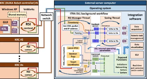
[image:2.612.49.566.433.713.2]The KRC4 controller comprises three main systems, which are represented in Fig. 1. The graphic user interface (GUI) allows the user to write and execute robot programs, through defining robot bases, tool parameters and by jogging the robot arm. This GUI runs within an embedded version of Windows XP®. Hidden from the user is a separate operating system called VxWorks®. This is a real-time operating system, which is designed for embedded applications [20]. The VxWorks system controls all robot drives and is used because of its multi-tasking capabilities, real-time performance and reliability. Although running on the same processor, the Windows XP and VxWorks operating systems are entirely separate from each other. Any information that is passed between them is sent over a virtual TCP/IP connection within the KRC architecture. There is no physical network cable but information is packed up, transmitted over the virtual connection, received and unpacked by the other system to be processed.
B. Robot Sensor Interface
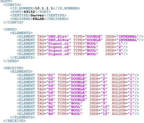
RSI runs under the VxWorks operating system in a real-time manner. It was purposely developed by KUKA to enable the communication between the robot controller and an external system (e.g. a sensor system or a server computer). Cyclical data transmission from the robot controller to the external system (and vice-versa) takes place in parallel to the execution of the KUKA Robot Language (KRL) program. Using RSI makes it possible to influence the robot motion or the execution of the KRL program by processing external data. The robot controller communicates with the external system via the Ethernet UDP/IP protocol. No fixed data frame is specified. The user can configure the template of the structure and the content of the data packets in an XML file, stored in the robot controller. Typical data packets, sent as ASCII packets by RSI to the external system, can include feedback Cartesian or axial coordinates, status of digital I/O signals and real-time operating parameters (e.g. drives currents and torques). Typical data packets received from the external system can include a number of Boolean, integer or double precision variables. Fig. 2 shows the XML template file defining the content of the packets transferred between RSI and the server computer, supporting all functionalities of the ITRA toolbox. The first part of the file comprises the connection parameters. SENTYPE is the identifier of the external system; it is checked by RSI to validate every data packet it receives. ONLYSEND defines the direction of the data exchange; FALSE indicates that RSI sends and receives data. The signals from the RSI context that are sent to the external system are defined in the SEND section. From this XML section, RSI automatically creates the XML ASCII packet that the KRC transmits. It includes the Cartesian actual coordinates (incorporated through the “DEF_RIst” keyword), the Axis-specific actual position of robot axes A1 to A6 (incorporated through the “DEF_AIPos” keyword) and the status of four KRC digital outputs. The ASCII packet received from the external system is parsed by the RSI context according to the XML template contained within the RECEIVE section. The RSI expects to receive eight double precision values and four Boolean values. The HOLDON attribute is set equal to “1” to make sure that if a data packet arrives too late to the RSI context, the most recent valid value is maintained in place of the value expected from the external system. The data packet received from the external system is processed within each machine cycle according to a data processing algorithm defined in the RSI configuration. This is generated through an object-based programming software application known as “ RSI-Visual”, using a library of RSI objects. Connecting multiple RSI objects creates a signal flow, which is called “RSI context”. In the KRL program, the RSI context can be loaded and the signal processing parallel to program execution can be activated and deactivated. The signal processing is performed at the RSI cycle rate. Two cycle durations are available: 12 ms and 4 ms. When the RSI context is activated, external data are processed by RSI and forwarded to a portion of the KRC memory that can be accessed by the KRL program. Appended to the end of every packet sent by RSI is a number identified as the Interpolation Cycle Counter (IPOC), which indicates the current timestamp
[image:3.612.315.566.117.332.2]of the data packet. RSI expects the external system to extract this timestamp and append it to the return packet, which must be received by the RSI context within the same cycle. If RSI does not receive the IPOC number back within the cycle duration, the packet is deemed late [19].
Fig. 2. RSI XML template supporting the functionalities of the ITRA toolbox.
III. INTERFACING TOOLBOX A. Architecture
ITRA is a C++ language library, designed to get feedback parameters from one or more robots simultaneously, to monitor the status of the running KRL robot programs and to trigger the progress of the robotic tasks from a server computer. C++ was chosen as programming language, since it is particularly suitable to develop highly robust communication and data processing algorithms that run in a reliable real-time manner. This language offers the programmer specific features to avoid the periodic, automated creation and disruption of allocated memory, known as garbage collection [21]. Other languages (e.g. C#), which do not allow the same level of control on the allocated memory, can lead to unexpected drops in software performances [22, 23].
each RSI XML packet must get a reply packet from the external system, the library needs to run a background thread that receives the RSI packets, parses the data, extracts the packet IPOC numbers and mirrors them to the robots. Such thread is critically important to maintain a robust communication with the robots. It is hereafter referred as RSI-Manager Thread (RMT). RMT cyclically checks if data are available on the UDP socket. As soon as a XML packet is in the socket, the RMT takes the value of the internal performance counter, to be used as timestamp (with µs resolution), and downloads the packet from the socket, decoding the IP address of the KRC that sent it. The IP address is used to identify the index associated to the robot. Then, the XML packet is parsed to extract the Cartesian and axial coordinates, the status of the digital outputs and the packet IPOC number.
It may be necessary to store the parsed positional feedback. Since writing data to files can cause disrupting delays in the RMT, ITRA uses a secondary auxiliary thread, hereafter referred as Saving Thread (ST). The transfer of the parsed data packets takes place through FIFO queues. These are container adaptors specifically designed to operate in a FIFO context (first-in first-out), where elements are inserted into one end of the container and extracted from the other end [21]. The number of FIFO queues initialized by ITRA is equal to the number of connected robot controllers, so the data packets arriving from a robot controller are sent to the queue identified by the same robot index. Each data packet is enqueued jointly with the timestamp taken at the time of reception. The ST continuously looks for new packets in the queues and saves them into files, empting the containers. Since these queues are used to hold robot feedback data, they are referred as “feedback queues” in Fig. 1. Besides sending each received data packet and its timestamp to a queue, a copy of the timestamped data is temporarily stored into a structured array containing the latest packets received from each robot controller. Every time a new packet is received from the n-th robot, the n-th element of the array is refreshed with the new data. This is useful to keep a copy of the most recent data received from the robots, even when the feedback queues are completely emptied by the ST.
Although the ST is initialized when the RMT is launched, it does not save any data packet into file by default. This is to enable the user to specify when it is necessary to save the robot positional feedback. An ITRA function (see below) allows enabling/disabling the saving of the positional feedback for each robot, specifying the data format to be sent to file. The ST creates a separate text file (.txt) for each connected robot, appending the feedback positional packets to the end of the files, when saving is enabled.
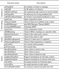
The hosting application can use the public functions of the ITRA library. These functions support the development of simple and complex integration software platforms, comprising modules like data acquisition, multiple robot task synchronization, interfacing with sensors, data visualization, robot path control and graphical user interfaces. ITRA contains 25 public functions, which can be divided in four groups, as it is shown in Table I. ITRA and its detailed reference manual, together with application examples and videos, can be
downloaded through the permanent link given in Appendix A1. A general description of the functions is given below.
B. Initializers
The functions referred as “Initializers” are designed to set internal fundamental operating parameters of the library (e.g. number of robots, IP addresses, type of connection and output directory). These functions can only be used before launching the background service threads (RMT and ST), except for setRobFeedbackOutput. This function sets the format of the positional feedback to store into files. It can be called before launching the threads, to pre-set the behavior of the ST at the start, or during runtime to enable/disable the saving of the positional feedback for one or more robots.
C. Networking
[image:4.612.314.565.346.640.2]The networking functions allow opening of the UDP connection, checking if data is available in the socket, starting the RMT to manage the connection with the robots, terminating the background service threads when they are no longer required and closing the connection. The saving thread is automatically launched and terminated together with the RSI-manager thread.
TABLE I
LIST OF ITRA FUNCTIONS DIVIDED INTO GROUPS
Function names Description
In
it
ia
li
ze
rs
setNumRob Set number of robots to manage setRobIP Set IP address of robot(s)
setRobConnType Set connection type (receive or receive/send) setOutputDir Set directory for saving feedback file setRobFeedbackOutput Set format of positional feedback to store
N
et
w
o
rk
in
g openConn Open connection socket
isDataAvailable Check if data are available in the socket startRSIManager Start RSI Manager Thread (RMT) terminateRSIManager Terminate RMT
closeConn Close connection socket
G
et
te
rs
isRSIRunning Check if RSI is running on a specific robot isRobotTaskActive Check if the robot task is active
isRobStill Check if the robot is still isRobMoveRequired Check if a robot move is required isDataAcquRequired Check if data acquisition is required getCurrPos Get current robot position getTimestamp Get current time
S
et
te
rs
allowRobotStart Allow robot to start its task allowRobMove Allow robot to move allowRobotFinish Allow robot to finish its task
requRealTimeEnd Request termination of real-time control requRobTaskEnd Request termination of current robot task setCartPos Set target position in Cartesian space setAxialPos Set target position in joint space setToolPathFromFile Set external control tool-path from file
D. Getters
hosting application as an array of double precision values. These can be used to monitor the robot position remotely from the server computer or to encode sensor data in a real-time fashion. Other getters return a Boolean value (TRUE or FALSE); these ITRA functions operate on the status of the four digital outputs inserted by RSI into the XML packets (see reference manual – Appendix A1). The function that gets the current clock time (the current timestamp) is the only function that does not query the array with the latest packets. It retrieves the current value of the internal library performance counter and returns a double precision timestamp expressed in microseconds (µs). The performance counter is the same clock used to timestamp the received packets sent to the feedback queue and (optionally) stored into files. Getting access to the same clock used to timestamp the feedback positional packets can be very useful, for example when it is necessary to encode sensor data through interpolated robot positions.
E. Setters
The “Setters” are functions able to influence the execution of predefined KRL programs and/or to control the robot tool-path. When called by the hosting applications, these functions generate command data packets addressed to one of the connected robots. The index of the target robot is given to the setters as an input. The generated command packets are sent to reserved FIFO queues, separated from the feedback queues. Such containers are referred as “command queues” (see Fig. 1) and they are also initialized by the ITRA constructor as soon as the library is loaded into the hosting application. The number of command queues is equal to the number of connected robot controllers, so each command packet can be sent to the queue identified by the same robot index targeted by the hosting application. The command packets are de-queued by the RSI-Manager Thread. After parsing the RSI packet received from the n-th robot controller, the RMT must reply to the robot through an XML string containing the data described in the RECEIVE section of the XML template (Fig. 2). The RMT looks for command packets available in the n-th command queue. If the queue is not empty, the packet at the front of the queue is de-queued and its content is concatenated into a string, according to the XML format expected by the RSI context. The setters allow flexible control of the robot arms, through the conventional meaning given to the value of the variables inserted into the XML packets sent to the robot controllers. Through some of the setters, the hosting application can trigger a robot to start its task, continue the task (e.g. after a phase during which the robot must be still) or allow the robot to terminate the task and return to the home position. Such type of control is achieved through acting on the values of the four Boolean variables, denoted as B1-B4 in Fig. 2. These critically important logical setters use software handshaking to guarantee the robustness of the messaging between robot controllers and external computer; they expect to receive a change in the status of the digital flags sent by RSI (the four KRC digital outputs), as an acknowledgement for the successful communication. Permission to proceed with the execution of the KRL program is not granted to the robot if such acknowledgement is not
received.
It is possible to control the robot tool-paths from the external computer, sending target positions to the robot controllers. ITRA has functions to set command coordinates in Cartesian-space and in joint-Cartesian-space. External robot control is achieved by transmitting the command coordinates through six of the double precision variables (D1-D6). The preferred robot speed and acceleration can also be controlled through the two remaining variables (D7 and D8). Further details are given in the ITRA reference manual (Appendix A1). Each command packet dequeued from the n-th command queue is also used to refresh the n-th element of a structured array containing the latest command packets sent to each robot controller. The copy of the latest command position sent to the n-th robot is used when the external path-control is active and the n-th command queue does not contain any new command packets. This ensures the robot reaches the latest commanded position and stops there, until a new target position is requested.
IV. APPLICATION EXAMPLES
This section presents two application examples, to demonstrate the use of ITRA. The architecture of the library provides flexibility to support the integration of a wide range of robotic systems. The first application is an example where a system with three robotic manipulators is used to perform automated photogrammetric and ultrasonic inspection of large high-value manufacturing parts. In this application, referred below as “robotically enabled sensing”, the robots follow predefined tool-paths, programmed in KRL through commercial off-line path-planning software. ITRA is used to control the execution of the robot KRL programs, synchronize the data acquisition with the robotic movement, timestamp the data packets and acquire robot positional feedback. The second application covers three control approaches, demonstrating the use of ITRA for achieving external control of robotic arms. They will show how significantly different results can be achieved by combining customized RSI-Visual configurations to the flexibility of the ITRA architecture described above. Whereas the RSI configurations (created through RSI-Visual) define the way external data are processed and used by the robot controller, ITRA provides robust communication between one or more robots and the external computer.
A. Robotically enabled sensing
Fig. 3. Representation of the robotic inspection application example [25].
The integrated system is capable of performing volumetric ultrasonic inspection of the part, through an ultrasonic probe manipulated by Robot #1. The ultrasonic instrumentation is linked to the server computer via a PCI Express bus [26]. The camera and the projector are both connected via USB links. ITRA has allowed the use of a single server computer for managing all aspects of the system, controlling the execution of all robotic tasks synchronously. Fig. 4 shows the RSI Visual configuration loaded into all robot controllers. Since the system is based on robots following predefined tool-paths (no external path control is used), the RSI configuration is very simple. Data exchange with the external computer is implemented using the RSI ETHERNET object. The name of the XML file (ITRA.xml) containing the template of the data to be exchanged (Fig. 2) is specified as one of the object parameters. The signals at the object inputs (the four digital outputs) are sent to the computer. The data received from the external computer are available at the object outputs. The eight double values (D1-D8) in the receive section of the XML template are available between Out1 and Out8. The four Boolean values (B1-B4) are mapped to the elements of an array ($SEN_PINT), which can be accessed by the KRL module. These four KRC digital outputs are used to track the execution status of the KRL program, whereas the Boolean values mapped to $SEN_PINT are used to trigger some key steps of the robot program. The library getters and the setters are high-level functions, respectively responsible for querying the status of the robot and formulating the correct command packets to achieve the specific objectives.
Fig. 4. RSI-Visual configuration loaded into each robot controller [25].
The ITRA-based logical workflow, for the operation of the described robotic inspection system, is given in Fig. 5. B. External control capabilities
[image:6.612.312.566.162.643.2]Robots have been quite successful in accomplishing tasks in well-known environments like a work cell within a factory. The much harder problem of a robot acting in unstructured and dynamic environments, like those humans normally act and live in, is still an open research area [27].
Fig. 5. ITRA-based logical workflow, for the operation of the described robotic inspection system.
[image:6.612.46.297.536.724.2]external control of robotic arms. Three different approaches are presented. Whereas the path-planning sub-problem is always dealt with by the computer hosting ITRA, where processing of machine vision data and/or other sensor data can take place to compute the robot target position, the trajectory planning subproblem can be managed by different actors of the system. In the first approach (hereafter referred to as KRL-based approach), the trajectory planning takes place at the KRL module level within the robot controller. The second approach has trajectory planning performed within the external computer, soon after path-planning, and is referred to as Computer-based approach. The third approach relies on a real-time trajectory planning algorithm implemented into the RSI configuration. Therefore, trajectory planning is managed by the RSI context and the approach is named as RSI-based approach.
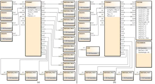
1) KRL-based approach
This approach is based on the use of ITRA in conjunction with the RSI configuration shown in Fig. 6a. This configuration maps the eight double precision values available at the outputs of the ETHERNET object to the first eight elements of an array of real numbers ($SEN_PREA), which is accessible from the KRL module. The ITRA setCartPos function can be used to send the target Cartesian space coordinates (X, Y, Z, A, B, C) and the desired speed and acceleration with which the target must be reached. The coordinates are mapped to $SEN_PREA[1-6], the speed gets mapped to $SEN_PREA[7] and the acceleration to $SEN_PREA[8]. Therefore, the array element values can be assigned to local variables in the KRL module and the target position can be reached through a linear (LIN) movement within a loop structure. The KRL code responsible for extracting the values stored in $SEN_PREA and moving the robot is the following:
» LOOP
» target_pos.x = $SEN_PREA[1] » target_pos.y = $SEN_PREA[2] » target_pos.z = $SEN_PREA[3] » target_pos.a = $SEN_PREA[4] » target_pos.b = $SEN_PREA[5] » target_pos.c = $SEN_PREA[6] » $VEL.CP = $SEN_PREA[7]/1000 » $ACC.CP = $SEN_PREA[8]/1000 » LIN target_pos
» IF ($SEN_PINT[13]==1) THEN » $OUT[14]=TRUE
» EXIT » ENDIF » ENDLOOP
In this example the coordinates are given in millimeters, whereas desired speed and acceleration are respectively given in m/s and m/s2. By modifying the KRL code, it is possible to
use point-to-point (PTP) movements, rather than LIN movements. It is also easy to customize the KRL code to control the robot through joint space coordinates (A1-A6) rather than Cartesian coordinates. In this case, the setAxialPos function should be used on the computer side. The external control can be terminated through the requRobTaskEnd function that sends
a Boolean flag to set $SEN_PINT[13] true and waits for $OUT[14] to became true too. Since the robot controller interprets the KRL module line by line, one limitation of this approach is that the robot must decelerate and stop at the target position. This is to allow the KRL interpreter to return to the beginning of the loop and extract the new target coordinates, and the required speed and acceleration from the $SEN_PREA array. This approach is unable to provide true real-time control of the robot, since a previously commanded target must be reached before a new target position can be assigned. Moreover, only PTP and LIN interpolations are available.
2) Computer-based approach
This second approach is based on the use of ITRA in conjunction with the RSI configuration shown in Fig. 6b. Here the target coordinates available at the output of the ETHERNET object are given to the inputs of the POSSCORR object, which allows Cartesian correction of the robot position within a defined range (limits specified in the object parameters). POSCORRMON is the object that limits the maximum overall Cartesian correction. The KRL code responsible for activating the motion guided by the external computer is reduced to the following line:
» RSI_MOVECORR()
Fig. 6. RSI-Visual configurations for external path control: KRL-based (a) and Computer-based (b) approach
In a similar way to the KRL-based approach, the limitation of the Computer-based approach is its necessity to wait until all trajectory points are sent before a new set of points can be streamed to the robot. The reason lies in the fact that a sudden interruption of the sequential transfer of control points would bring the robot motion to an immediate stop with a consequent peak/discontinuity in the velocity, acceleration and jerk. 3) RSI-based approach
Unlike the KRL-based and the Computer-based approaches, the RSI-based approach enables true real-time path control of KUKA robots based on KRC4 controllers. This approach permits fast online modifications to a planned trajectory, allowing robots to react to dynamic environments. Whereas the path-planning takes place in the server computer, trajectory planning has been implemented as an RSI configuration, employing the second-order trajectory generation algorithm presented in [29]. The approach can operate in Cartesian-space and in joint-space. While the robot is static or is travelling to a given position, the computer can send a new target position (together with the maximum preferred speed and acceleration) through the setCartPos or the setAxialPos functions. Due to the complexity of the relative RSI-Visual configurations (containing over 500 objects), they are not shown herein but they are available in the ITRA software package downloadable through the permanent link given in Appendix A1. Unlike the RSI configuration for the Computer-based approach, the target coordinates received by the RSI context are not passed to the POSCORR object. Such target coordinates are instead used to compute the optimal coordinates of the set point to send to the object through a two-fold algorithm. On the one hand, the set point is generated to guarantee a smooth transition from the
initial conditions (starting coordinates, velocity and acceleration) towards the final target position. On the other hand, the algorithm makes sure the evolution of the robot motion is constrained within the given maximum speed and acceleration. Fig. 7 compares two trajectories obtained through the KRL and the RSI-based approaches. A KR6 R900 AGILUS robot was used to test both approaches, using the same control points (P1, P2 and P3). The speed and the acceleration were set respectively to 2 m/s and 3 m/s2. The robot started from S.
In the first trajectory, the robot travelled through all control points and took 2.52sec to complete the path. This trajectory can be generated by both the KRL and the RSI-based approaches when, before commanding a new point, enough time is given to the robot to reach the previous target point.
[image:8.612.314.568.530.709.2]The second trajectory shows the adaptive behavior achievable through the RSI-based approach. This approach was used to simulate the situation where it is no longer necessary to reach a previously set point and a new target position is requested. Therefore, P2 and P3 were commanded after 0.25sec from the time when the previous points were set as target position. The robot adapted on-the-fly to the change of target position and the final target (P4) was reached in 1.61sec, with a smooth and continuous trajectory.
V. BENCHMARKING
The run-time of all ITRA functions was investigated by loading the library into MATLAB 2018a (64bit version), running within a computer with Intel i7-7700HQ CPU and 16GB of RAM. The computer was linked to one KR6 R900 AGILUS robot running a KRL module that contained all required lines to enable the execution of the ITRA functions. A. Function run-times
Each function was executed 100 times and the run times were recorded. Table II reports the resulting run time values in microseconds (µs), for x64 Windows10® and Linux operating systems. The table reports the 50th and the 75th percentiles
(respectively P50 and P75). Whereas P50 corresponds to the
median of the run time distribution, the 75th percentile provides
information about the spread of the values, since P75 is the run
time value that exceed 75% of the readings. The variability in the run time of each function was due to ITRA running on non-real-time platforms.
TABLE II
RUN-TIME FOR ALL ITRAFUNCTIONS.
Function names
Run time [µs]
Windows 10 Linux OS
P50 P75 P50 P75
In it ia li ze rs
setNumRob 24.2 28.9 11.1 12.6
setRobIP 9.0 10.1 5.3 6.0
setRobConnType 12.1 13.6 5.7 6.1
setOutputDir 17.9 20.5 9.9 10.4
setRobFeedbackOutput 10.5 11.6 4.1 4.3
N et w o rk in
g openConn 205.6 224.7 42.9 54.7
isDataAvailable 13.9 15.2 6.0 6.5
startRSIManager 1532.9 1601.8 65.4 76.0
terminateRSIManager 10.8 12.0 7.7 8.2
closeConn 78.5 90.4 20.9 23.7
G
et
te
rs
isRSIRunning 45.1 50.0 30.4 32.8
isRobotTaskActive 37.6 40.3 13.3 16.2
isRobStill 37.7 40.2 13.4 16.2
isRobMoveRequired 59.0 65.4 41.3 42.5
isDataAcquRequired 7.6 8.4 5.2 5.9
getCurrPos 40.5 42.3 35.8 39.4
getTimestamp 11.2 12.7 6.8 7.3
S
et
te
rs
allowRobotStart 26460.1 26558.1 27911.7 27950.8
allowRobMove 9630.5 11019.9 11869.1 11898.7
allowRobotFinish 23985.9 24035.8 23985.1 24011.1
requRealTimeEnd 96959.2 100000.2 102519.7 102565.0
requRobTaskEnd 11967.3 12003.9 11953.8 11971.5
setCartPos 41.7 43.9 16.3 31.2
setAxialPos 41.6 44.0 16.3 31.1
setToolPathFromFile 4143.9 4212.8 1376.6 1401.6
All functions were tested with the RSI context running at 4 ms cycle mode, with the exception of setToolPathFromFile, which was used for the Computer-based external control approach that is only supported by the 12 ms RSI cycle mode. The run-time of setToolPathFromFile depends on the number of command positions contained in the text file, which affects the time to load them into the library command queue. The function was tested with a file containing 250 positions. B. External control reaction times
The performance of the three external control approaches was also tested. Reaction time is the most important parameter in real-time control, since it measures the promptness of the system. Reaction time in humans is a measure of the quickness in which the organism responds to some sort of stimulus. The reaction time is defined as the latency between the stimulus and the very start of the reaction. The average reaction time for humans is 250 ms to a visual stimulus, 170 ms for an auditory stimulus, and 150 ms for a haptic stimulus [30]. The reaction speed plays a large part in everyone’s everyday life. Fast reactions can produce big rewards, for example saving a blistering soccer ball from entering the goal. Slow reaction times may come with consequences. Similarly, achieving small reaction time is crucial for robots that need to have real-time adaptive behaviors to respond to dynamic changes and/or to interact with humans.
The external control latency (or reaction time) is defined herein as the time interval between the instant a new target position becomes available on the external computer and is sent to the robot via setToolPathFromFile, setCartPos or setAxialPos and the instant the robot starts reacting to reach such commanded target. With ITRA running within MATLAB and saving robot feedback positions through the saving thread, the reaction time of each external control approach was measured 100 times through commanding the robot to move to a target from a static position. The timestamp of the first robot feedback positional packet, reporting a deviation greater or equal to 0.01 mm from the original home position, was compared with the timestamp taken by getTimestamp just before sending the target position to the robot. The resulting reaction times are given in Table III. Although the run times to send a target position to the robot, get the current position and obtain the timestamp are negligible (in the order of microseconds), the reaction times comprise such run times.
TABLE III
PERFORMANCE OF EXTERNAL CONTROL APPROACHES
External control approach RSI cycle Update rate
Reaction time [ms]
Windows 10 Linux OS
P50 P75 P50 P75 KRL-based 4 ms Variable 110.17 153.75 110.73 153.81 Computer-based 12 ms Variable 68.42 77.73 63.12 69.72 RSI-based 4 ms 250 Hz 29.26 31.08 30.14 31.40
and 80% better. The update rate of the first and second approach is variable, since a new target position can be commanded only after the previous target is reached. The update rate of the RSI-based approach is equal to the running frequency of the RSI context, so a new target position can be set every 4 ms with the robot expected to react within 30 ms (±2 ms). ITRA enables applications that go beyond the capabilities offered by native robot interface layers (RSI for KUKA KRC4 platforms). Whereas the native RSI adaptive real-time path-correction only works for small corrections (few millimeters), for which accurate trajectory planning is not required, this work enables adaptive real-time control for large displacements. This allows achieving prompt robot reactions to reach distant target poses/positions, which can be commanded on the fly at any time during movement along a trajectory.
VI. CONCLUSION
The paper presented a new Interfacing Toolbox for Robotic Arms (ITRA). It is a fully flexible and extensible toolbox, which addresses three current gaps in the control approaches for industrial robotic systems. Most importantly, it enables adaptive robotic system with fast reactions. Secondly, it is capable of controlling multiple robots simultaneously. Thirdly, it is cross-platform compatible and allows great flexibility between different computer architectures. Due to platform availability during its development, the current version of ITRA only works with KUKA hardware. ITRA contains high-level functions for robust connectivity between multiple KRC4 KUKA robots and a server computer. The toolbox is designed to speed-up efficient integration of robotic systems. Crucially, ITRA can be used to enable real-time adaptive robot behavior, maximizing the robot promptness and respecting dynamic constraints (maximum accelerations and velocities). ITRA enables applications that go beyond the capabilities offered by native software robotic interface layers. Several application examples have also been provided to demonstrate how the toolbox can be used to integrate robotic systems with multiple robots, sensors and instrumentation and how to achieve external control through three different approaches. ITRA allows controlling robot arms with update rates up to 250 Hz, achieving robot reaction times as short as 30ms. The benchmarking provided accurate measurement of the run-time of all ITRA functions. Current work is focusing on testing ITRA performance on real-time platforms and enabling support for java-based KUKA robot platforms and for robots produced by different manufacturers. This will be addressed by enabling the ITRA user to customize the communication protocol (e.g. TCP/IP, EtherCAT, UDP/IP, etc.) and the templates for incoming and outgoing communication packets.
APPENDIX
A1 - ITRA library and user manual package:
https://doi.org/10.15129/bfa28b77-1cc0-4bee-88c9-03e75eda83fd
REFERENCES
[1] G.-Z. Yang et al., "The grand challenges of Science Robotics," Science Robotics, vol. 3, no. 14, pp. 1-14, Jan. 2018.
[2] P. I. Corke, Robotics, Vision and Control: Fundamental Algorithms in MATLAB. Berlin: Springer, 2011.
[3] A. Breijs, B. Klaassens, and R. Babuška, "Automated design environment for serial industrial manipulators," Industrial Robot: An International Journal, vol. 32, no. 1, pp. 32-34, 2005.
[4] G. L. Mariottini and D. Prattichizzo, "EGT for multiple view geometry and visual servoing: robotics vision with pinhole and panoramic cameras," Robotics & Automation Magazine, IEEE, vol. 12, no. 4, pp. 26-39, 2005.
[5] M. Toz and S. Kucuk, "Dynamics simulation toolbox for industrial robot manipulators," Computer Applications in Engineering Education, vol. 18, no. 2, pp. 319-330, 2010.
[6] F. Chinello, S. Scheggi, F. Morbidi, and D. Prattichizzo, "Kuka control toolbox," Robotics & Automation Magazine, IEEE, vol. 18, no. 4, pp. 69-79, 2011.
[7] T. Pawletta et al., "Robotic control & visualization toolbox for MATLAB," IFAC-Papers On Line, vol. 48, no. 1, pp. 687-688, 2015. [8] E. Dean-Leon, S. Nair, and A. Knoll, "User friendly Matlab-toolbox for
symbolic robot dynamic modeling used for control design," in Robotics and Biomimetics (ROBIO), 2012 IEEE International Conference on, 2012, pp. 2181-2188: IEEE.
[9] H. Bruyninckx, "Open robot control software: the OROCOS project," in Proceedings 2001 ICRA. IEEE international conference on robotics and automation (Cat. No. 01CH37164), 2001, vol. 3, pp. 2523-2528: IEEE. [10] A. Brooks, T. Kaupp, A. Makarenko, S. Williams, and A. Oreback, "Towards component-based robotics," in 2005 IEEE/RSJ International Conference on Intelligent Robots and Systems, 2005, pp. 163-168: IEEE. [11] A. Blomdell et al., "Extending an industrial robot controller: implementation and applications of a fast open sensor interface," IEEE Robotics & Automation Magazine, vol. 12, no. 3, pp. 85-94, 2005. [12] B. Inner and S. Kucuk, "A novel kinematic design, analysis and
simulation tool for general Stewart platforms," Simulation, vol. 89, no. 7, pp. 876-897, 2013.
[13] M. Safeea and P. Neto, "KUKA Sunrise Toolbox: Interfacing Collaborative Robots with MATLAB," arXiv preprint arXiv:1709.01438, 2017.
[14] S. Mokaram et al., "A ROS-integrated API for the KUKA LBR iiwa collaborative robot," IFAC-PapersOnLine, vol. 50, no. 1, pp. 15859-15864, 2017.
[15] R. Bischoff et al., "The KUKA-DLR Lightweight Robot arm-a new reference platform for robotics research and manufacturing," in Robotics (ISR), 2010 41st international symposium on and 2010 6th German conference on robotics (ROBOTIK), 2010, pp. 1-8: VDE.
[16] R. Demming and D. J. Duffy, Introduction to the Boost C++ Libraries; Volume I-Foundations. Datasim Education BV, 2010.
[17] ABB, Application manual - Robot Reference Interface. 2013. [18] Stäubli, uniVAL Drive. 2018.
[19] KUKA, KUKA.RobotSensorInterface 3.2 Documentation - Version: KST RSI 3.2 V1. 2013.
[20] A. Barbalace, A. Luchetta, G. Manduchi, M. Moro, A. Soppelsa, and C. Taliercio, "Performance comparison of VxWorks, Linux, RTAI and Xenomai in a hard real-time application," in Real-Time Conference, 2007 15th IEEE-NPSS, 2007, pp. 1-5: IEEE.
[21] B. Stroustrup, The C++ programming language. Pearson Education, 2013.
[22] K. D. Nilsen, "Reliable real-time garbage collection of C++," Computing Systems, vol. 7, no. 4, pp. 467-504, 1994.
[23] K. Houstoun and E. Briggs, "Rapid addition leverages Microsoft .NET 3.5 Framework™ to build ultra-low latency FIX and FAST processing," ed, 2014.
[24] C. Mineo, S. Pierce, B. Wright, I. Cooper, and P. Nicholson, "PAUT inspection of complex-shaped composite materials through six DOFs robotic manipulators," Insight-Non-Destructive Testing and Condition Monitoring, vol. 57, no. 3, pp. 161-166, 2015.
[25] C. Mineo et al., "Flexible integration of robotics, ultrasonics and metrology for the inspection of aerospace components," in AIP Conference Proceedings, 2017, vol. 1806, no. 1, p. 020026: AIP Publishing.
[26] T. Fountain, A. McCarthy, and F. Peng, "PCI Express: an overview of PCI Express, cabled PCI Express, and PXI Express," in 10th ICALEPCS Int. Conf. on Accelerator & Large Expt. Physics Control Systems, 2005. [27] T. Kunz, "Real-Time Motion Planning for a Robot Arm in Dynamic
Environments," Verlag nicht ermittelbar, 2009.
approach," Robotics and Computer-Integrated Manufacturing, vol. 37, pp. 1-12, 2016.
[29] R. Haschke, E. Weitnauer, and H. Ritter, "On-line planning of time-optimal, jerk-limited trajectories," in Intelligent Robots and Systems, 2008. IROS 2008. IEEE/RSJ International Conference on, 2008, pp. 3248-3253: IEEE.
[30] G. R. Grice, R. Nullmeyer, and V. A. Spiker, "Human reaction time: toward a general theory," Journal of Experimental Psychology: General, vol. 111, no. 1, p. 135, 1982.
Carmelo Mineo was born in Palermo
(Italy) in 1987. He studied Mechanical Engineering at the University of Palermo, where he obtained the Bachelors’ degree in 2009 and the Masters’ degree in 2011.
In 2012, with a background in mechanical engineering, laser ultrasound and NDT testing, he joined the Centre for Ultrasonic Engineering (CUE) of the department of Electrical and Electronic Engineering at the University of Strathclyde to undertake a PhD in Automated Non-Destructive Inspection of Large and Complex Geometries of Composite Materials. Dr Mineo became a Research Associate of the University of Strathclyde in 2015 and a Research Fellow in 2018. His current research interests comprise all aspects of the operation of robotic cells, including programming, instrument interfacing and data collection. He has vast experience in industrial engineering areas such as robotics, sensors, mechanical design, software, system integration, interfacing and control.
Cuebong Wong obtained a Masters with
Distinction in Electrical and Mechanical Engineering at the University of Strathclyde (UK) in 2016. While undertaking his Masters, he joined the Control Robotics Intelligence (CRI) Group at Nanyang Technological University (Singapore) as part of an international exchange to conduct an investigation into human locomotion. He joined the Department of Design, Manufacture and Engineering Management (DMEM) to undertake a PhD in Robotics and Autonomous Systems for Harsh Environments, which was funded by the EPSRC Doctoral Training Partnership (DTP) 2016-2017 program. His current research interests lie in adaptive task planning, motion planning and machine learning for robotic manipulators and mobile robots that interact with challenging environments. Mr Wong became a Member (M) of the Institution of Engineering and Technology (IET) in 2017, and is an alumnus of the Engineering Leaders Scholarship program with the Royal Academy of Engineering.
Momchil Vasilev was born in Sofia
(Bulgaria) in 1994. He received a BEng with Honours in electronic & electrical engineering from the University of Strathclyde, Glasgow, in 2017.
From 2016 to 2017 he was a part time researcher at the Centre for Ultrasonic Engineering (CUE) in the University of Strathclyde and in 2017 he joined the group as a PhD researcher. His interests include in-process ultrasonic inspection of welds, non-destructive evaluation, sensor enabled robotic welding and sensor fusion for robotic applications.
Charles MacLeod is a Lecturer in the
Centre for Ultrasonic Engineering. After being awarded a Masters in Electrical and Mechanical Engineering with Distinction at Strathclyde, Charles then went on to undertake a PhD in Automated Non – Destructive Evaluation. While undertaking his PhD Charles, was seconded to Spirit AeroSystems, in Prestwick to undertake Knowledge Exchange activities built on fundamental EPSRC funded research. Charles was awarded the prestigious University of Strathclyde EPSRC Doctoral Prize for 2014, for his work investigating automated NDE. Charles has vast experience in electrical and mechanical engineering areas such as robotics, sensors, electronics, mechanical fixturing and software.
S. Gareth Pierce is based in the Centre for
Ultrasonic Engineering (CUE) at The University of Strathclyde. With a background in Applied Physics and Engineering, his research interests include robotic systems for Non-Destructive Testing & Evaluation (NDT&E), ultrasonics and acoustics, structural health
monitoring, applied optics,
instrumentation and machine learning. He is EU Robotics member for the UK Research Centre in Non-Destructive Testing (RCNDE), member of the Association for Robots in Architecture, and Technical Committee member for the European Workshop on Structural Health Monitoring. He is currently visiting Professor at Högskolan Väst, Trollhättan, Sweden.
Erfu Yang became a Member (M) of IEEE
in 2005. He was born in Gansu province, China. In 2008, he received his Ph.D. degree in robotics and autonomous Systems from the University of Essex, Colchester, UK.
machine learning and artificial intelligence including multi-agent reinforcement learning, fuzzy logic, neural networks, bio-inspired algorithms, and cognitive computation, etc.
![Fig. 3. Representation of the robotic inspection application example [25].](https://thumb-us.123doks.com/thumbv2/123dok_us/1346861.88358/6.612.312.566.162.643/fig-representation-robotic-inspection-application-example.webp)