City, University of London Institutional Repository
Citation
:
Sun, Z. ORCID: 0002-3862-7939, Li, Q. and Bruecker, C. ORCID: 0000-0001-5834-3020 (2018). Short wavelength instability in the vortex ring during impingement onto a solid wall. Paper presented at the 19th International Symposium on Applications of Laser and Imaging Techniques to Fluid Mechanics, 16-19 Jul 2018, Lisbon, Portugal.This is the accepted version of the paper.
This version of the publication may differ from the final published
version.
Permanent repository link:
http://openaccess.city.ac.uk/21650/Link to published version
:
Copyright and reuse:
City Research Online aims to make research
outputs of City, University of London available to a wider audience.
Copyright and Moral Rights remain with the author(s) and/or copyright
holders. URLs from City Research Online may be freely distributed and
linked to.
The Short-Wavelength Instability in the Impinging Vortex Ring
Measured by Scanning-PIV
Zhengzhong Sun, Qianhui Li, Christoph Bruecker
Department of Mechanical Engineering and Aeronautics, City, University of London, UK
1. Background
The vortex ring is recently recognized as an efficient cooling methodology, thus giving rise to the unsteady fluid dynamic problem of impinging vortex ring. The head-on collision of vortex ring towards a surface is also widely adopted as a simplified model to understand the noise problem of an impinging jet. Considering its engineering background, thorough appreciation of the impingement process is essential for efficient engineering application.
1.1 Vortex ring impingement at a glance
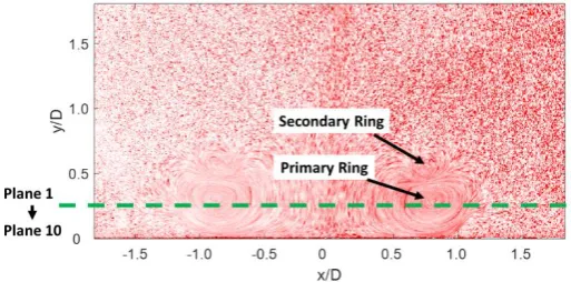
[image:2.595.153.447.558.729.2]Experiments on impinging vortex ring are not few. Earlier flow visualization [1] using colored dye revealed that the original ring expands in diameter when the wall is approached. In the meantime, a boundary layer is formed on the flat surface, which is subject to radial adverse pressure gradient. As soon as the boundary layer separates, it forms into a secondary ring in counter rotation, which subsequently orbits into the primary ring. The secondary ring is first subject to azimuthal instability, which manifests as the wave-like undulation along the ring torus. The appearance of azimuthal instability at the secondary ring triggers the interaction of the two vortex rings and leads to the loss of coherence and rapidly gives rise to turbulence. Note that, a tertiary ring can also be produced when the secondary ring moves into the primary one. The recent visualization experiment using laser induced fluorescent technique in the axisymmetric plane by New et al. [2] confirmed the previous observations. The authors reported the impingement process in the wall-parallel planes through the Scanning-PIV technique [3], which offers a perspective not available before. In this experiment, the azimuthal instability was measured quantitatively, and its evolution was revealed through auto-correlation method.
1.2 The short wave-length instability
[image:3.595.152.455.229.368.2]Apart from experimental works, a DNS study [4] made further advance about this flow problem and reported a short-wavelength instability (SWI) that develops on the impinging vortex ring, which was not noticed before. Different from the viscous wall condition in the experiment, this DNS simulation artificially applied the symmetric boundary condition at the impingement plane. Viscosity on the wall is hence neglected and no boundary layer is formed, nor is the generation of secondary ring. A question is naturally raised: is the SWI still present in reality where viscous wall is present? This question thus motivates the present experimental study using Scanning-PIV.
Figure 2. The short-wavelength instability visualized through DNS (left) and its lose-up view (right) [4].
2. Experimental Setup
The experiment is carried out in a water tank with dimensions of 300 (W) x 300 (L) x 400 (H) mm3. The vortex ring is produced through a piston-nozzle mechanism. The nozzle has outlet
diameter of 30 mm. The piston is driven by a LinMot linear motor. In the experiment, the piston stroke is set to 85 mm, resulting in a formation number of 2.83. The piston velocity is 58.5 mm/s and the resulted vortex ring has a velocity of 40.6 mm/s. The piston based Reynolds number is 1,755 and the circulation based Reynolds number is 1,800. A square transparent glass plate with size of 150 (W)x150 (L) is place 130 mm below the nozzle outlet for impingement.
The impingement process is measured by Scanning-PIV. The flow illumination is provided through a 5W continuous wave laser with beam diameter of approximately 3mm. The laser sheets are formed through a drum scanner, which contains 20 mirrors evenly distributed
along the drum’s circumference. In the present experiment, the mirror arrangement
the scanner and the exposure time is set 780 µs to match the time used in slice formation. A sketch of the flow facility and the measurement system is shown in figure 3.
Each measurement generates a data ensemble of 8000 images, they are later grouped into 10 slices to carry out sequential cross-correlation. The time separation between two images in the same slice is 1/125 s, which ensures time-resolved measurement. Apart from the Scanning-PIV measurement, a typical planar PIV measurement is carried out in the vertical plane which passes through the vortex ring axis. This planar PIV measurement records the impingement through a conventional point of view, which has been adopted by most of the previous works.
[image:4.595.159.454.233.367.2]
Figure 3. Experimental setup: (left) the conceptual sketch; (right) the drum scanner and mirror arrangement.
3 Results
3.1 An overview of the impingement
The present impingement is found to follow the typical process as visualized before. Synthetic particle images are generated by adding 10 images together, so that the particle trajectories can be visualized. One snapshot of the synthetic image is shown in figure 4, where the primary and secondary vortex rings are both visualized through the swirling particles. This snapshot corresponds to the moment when the secondary ring moves on top of the primary one. In this figure, the top scanning laser slice is also indicated, which passes through the median plane of the primary ring. The rest of the scanning laser slice moves progressively to the lower positions with the downward step of 1mm.
[image:4.595.167.424.596.723.2]In order to reveal the impingement process, the radial velocity Ur along the entire radius at
phase angle θ=0° is extracted from the data ensemble and plotted along the temporal axis. The results in Plane 9 is shown in figure 5. It is rather clear that the primary vortex ring expands from the snapshot N=1200 to N=2100, which is determined through the outward motion of the peak Ur. Together with the expansion of the primary ring, the secondary ring is
produced at around N=2000, when negative Ur appears beyond positive Ur. Tertiary ring is
produced at around N=3000, as revealed through the simultaneous appearance of the positive and negative Ur. It is also conjectured that a fourth ring also tends to form at N=4000.
From N=4500, the positive Ur has intermittent appearance and the consistent appearance of
Ur is finally terminated at around N=5200, which suggests the interaction of the primary and
[image:5.595.98.489.258.528.2]secondary rings.
Figure 5. Temporal evolution of the radial velocity Ur [cm/s] (a) and axial vorticity ωz [1/s] (b)
along the radius at θ=0° in Plane 9 (the bottom plane).
The interaction process can be better represented through the axial vorticity ωz. The
alternating axial vorticity magnitudes begin to show up at N=4200, suggesting the initiation of the azimuthal instability. Since the axial vorticity and intermittency of the radial velocity appear simultaneously, they are closely linked. It can be conjectured that the latter is caused by the former. The alternating strips of positive and negative vorticity persist from N=4200 to N=7000, which suggests the duration of the interaction process. After N=7000, the coherence of vorticity is completely lost and turbulence is generated.
understand this small-scale activity, the horizontal plane is investigated in the following sub-section.
3.2 Visualization of the Short-Wavelength Instability
[image:6.595.93.512.485.632.2]The snapshot at N=1968 is chosen to reveal the high-frequency undulation observed in the previous section. The contours of radial velocity and axial vorticity within the bottom plane (Plane 9) are shown in figure 6. This snapshot corresponds to the moment when the secondary ring is being formed. In the contour of radial velocity, the primary ring is indicated by the circular positive radial velocity, while the secondary ring is represented by the negative magnitude. The weaker magnitude of the secondary can be found through the much smaller negative velocity magnitude, namely about -2 cm/s. The non-smooth interface between the two rings is also visualized, and the interface corrugation is more pronounced on the right-hand side. The interface undulation gives rise to axial vorticity as shown in contour of axial vorticity. In association with deeper interface undulation, stronger axial vorticity magnitude is produced on the right. It is now apparent that the small-scale axial vorticity is aligned with the circular interface. More importantly, the positive and negative axial vorticity appear in an alternating pattern, conforming with vorticity pattern caused by an azimuthal instability. As the top and bottom portions of the circular interface are cropped by the camera field of view, accurate identification of the wavenumber is not possible. But it is certain that the wavenumber of the interface instability is of much shorter wavelength than the wavenumber in the secondary ring and that exhibited in the transition of this ring, which is around 7. The present SWI is different from that in the DNS study [4], as the SWI in the latter appears simultaneously with the long-wavelength instability. So far it can be concluded that the SWI appears when the secondary ring is being produced and it is at the interface between the primary and secondary ring.
Figure 6. Contour of radial velocity (left) and axial vorticity (right) at N=1888 in Plane 9.
4 Conclusions
manifests in the coherent generation of axial vortical and the intermittent positive radial velocity. Following the progress of interaction, the coherence of primary ring is completely lost. Special attention is paid to the SWI revealed by other researchers. The SWI is found to appear at the interface between the primary and secondary rings, and makes the interface corrugated. The present SWI does appear earlier than the vortex ring interaction, hence it is independent from the long-wavelength azimuthal instability wave behaved by the secondary ring.
References
[1] JDA Walker, CR Smith, AW Cerra, TL Doligalski, The impact of a vortex ring on a wall, J. Fluid Mech., 181:99-140, 1987.
[2] TH New, S Shi, B Zhang, Some observations on vortex-ring collision upon inclined surface, Exp. Fluids, 57:109, 2016.
[3] Z Sun, Q Li, C Bruecker, Vortex ring impingement measured by Scanning-PIV, 12th
International Symposium on Particle Image Velocimetry, June 18-22, 2017, Busan, Korea.
![Figure 1. The impingement process visualized through laser induced fluorescent. [2]](https://thumb-us.123doks.com/thumbv2/123dok_us/1391510.92289/2.595.153.447.558.729/figure-impingement-process-visualized-laser-induced-fluorescent.webp)
![Figure 2. The short-wavelength instability visualized through DNS (left) and its lose-up view (right) [4]](https://thumb-us.123doks.com/thumbv2/123dok_us/1391510.92289/3.595.152.455.229.368/figure-short-wavelength-instability-visualized-dns-left-right.webp)
![Figure 5. Temporal evolution of the radial velocity Ur [cm/s] (a) and axial vorticity ωz [1/s] (b) along the radius at θ=0° in Plane 9 (the bottom plane)](https://thumb-us.123doks.com/thumbv2/123dok_us/1391510.92289/5.595.98.489.258.528/figure-temporal-evolution-radial-velocity-vorticity-radius-plane.webp)

