This is a repository copy of
FE modelling of CFRP machining- prediction of the effects of
cutting edge rounding
.
White Rose Research Online URL for this paper:
http://eprints.whiterose.ac.uk/148453/
Version: Published Version
Article:
Duboust, N., Pinna, C. orcid.org/0000-0002-9079-1381, Ghadbeigi, H.
orcid.org/0000-0001-6507-2353 et al. (4 more authors) (2019) FE modelling of CFRP
machining- prediction of the effects of cutting edge rounding. Procedia CIRP, 82. pp.
59-64. ISSN 2212-8271
https://doi.org/10.1016/j.procir.2019.04.037
eprints@whiterose.ac.uk https://eprints.whiterose.ac.uk/ Reuse
This article is distributed under the terms of the Creative Commons Attribution-NonCommercial-NoDerivs (CC BY-NC-ND) licence. This licence only allows you to download this work and share it with others as long as you credit the authors, but you can’t change the article in any way or use it commercially. More
information and the full terms of the licence here: https://creativecommons.org/licenses/
Takedown
If you consider content in White Rose Research Online to be in breach of UK law, please notify us by
ScienceDirect
Available online at www.sciencedirect.com Available online at www.sciencedirect.com
S
D
Procedia CIRP 00 (2017) 000–000
www.elsevier.com/locate/procedia
2212-8271 © 2017 The Authors. Published by Elsevier B.V.
Peer-review under responsibility of the scientific committee of the 28th CIRP Design Conference 2018.
28th CIRP Design Conference, May 2018, Nantes, France
A new methodology to analyze the functional and physical architecture of
existing products for an assembly oriented product family identification
Paul Stief *, Jean-Yves Dantan, Alain Etienne, Ali Siadat
École Nationale Supérieure d’Arts et Métiers, Arts et Métiers ParisTech, LCFC EA 4495, 4 Rue Augustin Fresnel, Metz 57078, France
* Corresponding author. Tel.: +33 3 87 37 54 30; E-mail address: paul.stief@ensam.eu
Abstract
In today’s business environment, the trend towards more product variety and customization is unbroken. Due to this development, the need of agile and reconfigurable production systems emerged to cope with various products and product families. To design and optimize production systems as well as to choose the optimal product matches, product analysis methods are needed. Indeed, most of the known methods aim to analyze a product or one product family on the physical level. Different product families, however, may differ largely in terms of the number and nature of components. This fact impedes an efficient comparison and choice of appropriate product family combinations for the production system. A new methodology is proposed to analyze existing products in view of their functional and physical architecture. The aim is to cluster these products in new assembly oriented product families for the optimization of existing assembly lines and the creation of future reconfigurable assembly systems. Based on Datum Flow Chain, the physical structure of the products is analyzed. Functional subassemblies are identified, and a functional analysis is performed. Moreover, a hybrid functional and physical architecture graph (HyFPAG) is the output which depicts the similarity between product families by providing design support to both, production system planners and product designers. An illustrative example of a nail-clipper is used to explain the proposed methodology. An industrial case study on two product families of steering columns of thyssenkrupp Presta France is then carried out to give a first industrial evaluation of the proposed approach.
© 2017 The Authors. Published by Elsevier B.V.
Peer-review under responsibility of the scientific committee of the 28th CIRP Design Conference 2018.
Keywords:Assembly; Design method; Family identification
1. Introduction
Due to the fast development in the domain of communication and an ongoing trend of digitization and digitalization, manufacturing enterprises are facing important challenges in today’s market environments: a continuing tendency towards reduction of product development times and shortened product lifecycles. In addition, there is an increasing demand of customization, being at the same time in a global competition with competitors all over the world. This trend, which is inducing the development from macro to micro markets, results in diminished lot sizes due to augmenting product varieties (high-volume to low-volume production) [1]. To cope with this augmenting variety as well as to be able to identify possible optimization potentials in the existing production system, it is important to have a precise knowledge
of the product range and characteristics manufactured and/or assembled in this system. In this context, the main challenge in modelling and analysis is now not only to cope with single products, a limited product range or existing product families, but also to be able to analyze and to compare products to define new product families. It can be observed that classical existing product families are regrouped in function of clients or features. However, assembly oriented product families are hardly to find.
On the product family level, products differ mainly in two main characteristics: (i) the number of components and (ii) the type of components (e.g. mechanical, electrical, electronical).
Classical methodologies considering mainly single products or solitary, already existing product families analyze the product structure on a physical level (components level) which causes difficulties regarding an efficient definition and comparison of different product families. Addressing this
Procedia CIRP 82 (2019) 59–64
2212-8271 © 2019 The Authors. Published by Elsevier B.V.
Peer-review under responsibility of the scientiic committee of The 17th CIRP Conference on Modelling of Machining Operations 10.1016/j.procir.2019.04.037
© 2019 The Authors. Published by Elsevier B.V.
Peer-review under responsibility of the scientiic committee of The 17th CIRP Conference on Modelling of Machining Operations
Keywords: Composite; Cutting Edge; Fibre Reinforced Plastic; FEM; Machining; Chip
1. Introduction
Carbon fibres are abrasive and are well known to cause rapid wear of the cutting tool by edge chipping, cutting edge rounding (CER) and edge profile flattening during the process of machining [1]. Surface quality can be problematic when machining of CFRP laminates, and a sharp cutting edge is required to prevent machining induced defects. Denkena and Bierman, [2] reviewed the influence of cutting edge geometry in material removal processes and identified cutting edge characterisation methods . Tool ageing has been shown to be a significant factor in the production of machining induced defects, including fibre pull-out, pitting and delamination. Therefore, predicting the effects of cutting edge rounding on a CFRP machining process is important to gain an understanding of the changes to the generated cutting forces, machining induced defects and part integrity. Increasingly, the use of finite element (FE) modelling techniques to predict the CFRP
machining process has been used by researchers [3],[4],[5]. Previous researchers have used the Hashin damage model with equivalent homogenous material (EHM) approach to predict the cutting forces in orthogonal cutting [3],[4],[6]. Further, FE methods have been applied to predict the delamination factor in drilling of CFRP [7]. Previous research by the authors has predicted cutting forces in CFRP machining using 2D and 3D FE models [8]. However, limited research has predicted the effects of tool wear using CER metric for a CFRP machining process. It has been shown that capturing machining forces will be useful when implemented in an on-machine real time process monitoring strategy [9]. Therefore this paper will present a new method for predicting the effects of cutting tool edge wear on machining forces, during an edge trimming process, with the use of an implicit FE model and MSC Marc software. A 2D plane stress equivalent homogeneous material approach will be used with a Hashin damage model to characterise composite material progressive failure. Cutting
S
D
17th CIRP Conference on Modelling of Machining Operations
FE modelling of CFRP machining- prediction of the effects of cutting edge
rounding
Nicolas Duboust
a*, Christophe Pinna
b, Hassan Ghadbeigi
b, Andrew Collis
c, Sabino
Ayvar-Soberanis
a, Kevin Kerrigan
a, R Scaife
aaAMRC, Advanced Manufacturing Park, Wallis Way, Catcliffe, Rotherham S60 5TZ, UK bDepartment of Mechanical Engineerering, University of Sheffield
cRolls-Royce, 62Buckingham Gate, London, UK
* Corresponding author. E-mail address: n.duboust@sheffield.ac.uk
Abstract
60 Nicolas Duboust et al. / Procedia CIRP 82 (2019) 59–64
forces will be predicted at increasing levels of tool wear, with increasing edge radii, and the FE results will be validated by experiment. Additionally, the magnitude of each of the composite failure index and failure mechanisms on different fibre orientations will be assessed using Hashin damage model.
2. Experiment
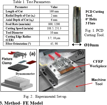
CFRP has been edge trimmed using a zero-helix, three flute PCD tool, as shown in Fig.1. The CFRP material, which has been manufactured from pre-preg and autoclave cured, has a uni-directional lay-up and a 6mm laminate thickness. The material has been machined in two different fibre orientations at 90 ° and +45 °, where the orientations are defined in [10]. The specimens of length 160 mm and thickness 6 mm were CNC machined with parameters as detailed in Table 1. An image of the fixture used to clamp the samples is shown in Fig.2. In this experiment, the effects of cutting tool wear will be measured by experiment, in new and worn cutting tool conditions, and the cutting edge radius is measured optically using an Alicona Infinite Focus SL. The cutting tool was measured to have an edge radius of 3.7 and 10 µm, for the new and used tool condition respectively. Each of the tools was tested in new and worn condition, at the two levels of feed rate, cutting speed and fibre orientation, and each test was repeated once to achieve a total of 32 tests. Machining was completed on a Cincinatti FTV machine tool using cutting fluid. The cutting fluid was an oil-water based emulsion which will remove cut particles, improve cooling and decrease friction in the cutting zone. The cutting forces have been measured in the cutting direction using a Kistler Dynamometer, which is shown in Fig.2. The mean Fx cutting force, which is parallel to the feed direction of the cutting tool, has been calculated and compared with FE model predictions.
3. Method- FE Model
To generate the edge trimming model a 2D implicit solver has been applied using finite element software MSC Marc. This engaged an equivalent homogeneous material approach to model the CFRP material properties, this method applies orthotropic behaviour, -where the Young’s modulus is different in the principle fibre orientations. The material principle stiffness components are applied in parallel and transverse
directions to the carbon fibres alignment. The CFRP is made up of two parts, consisting of epoxy thermosetting matrix and carbon fibres, which has properties as shown in Table 2. The cutting tool tip is manufactured from polycrystalline diamond (PCD) which has a very high hardness and resistance to abrasive wear mechanism. An elastic modulus of 925 GPa was applied to the tool tip using PCD properties confirmed in the literature [11]. The rest of the tool body has been given rigid body constraints. To model progressive failure of CFRP material a Hashin damage model was applied, including four different failure types: 1) fibre tension, 2) fibre compression, 3) matrix tension and 4) matrix compression [12]. The Hashin failure modes are calculated for each of the element integration points, and the model allows a reduction in the material stiffness by a progressive accumulation of different failure modes. Thermomechanical effects have been negated from the FE model due to the use of cutting fluid to cool the workpiece.
Mechanical Property Value
Tensile Modulus- (E1t) (GPa) 148
Tensile Strength- (Xt) (MPa) 2375
Transverse Tensile Modulus (E2t) (GPa) 51
Transverse Tensile Strength (Yt) (MPa) 68
Compressive Modulus (E1c) (GPa) 119
Compressive Strength (Xc) (MPa) 1465
Poisson’s Ratio ( ) 0.3
Inter-laminar Shear Strength (S13) (MPa) 113
In Plane Shear Strength (S12) (MPa) 112
[image:3.595.325.541.292.435.2]In Plane Shear Modulus (G12) (GPa) 4.7
Table 2. Unidirectional CFRP Mechanical Properties
Fig. 1. PCD Cutting Tool.
Parameter Value Length of Cut 160 mm
Radial Depth of Cut (ae) 2 mm
Axial Depth of Cut (ap) 6 mm
Feed Rate (mm/min) 800, 1200
Cutting Speed (m/min) 188.5, 251.3
Tool Diameter 10 mm
Cutting Edge Radius
(CER) 3.7, 10 µm Fibre Orientation (°) 45, 90
Fig. 2. Experimental Set-up.
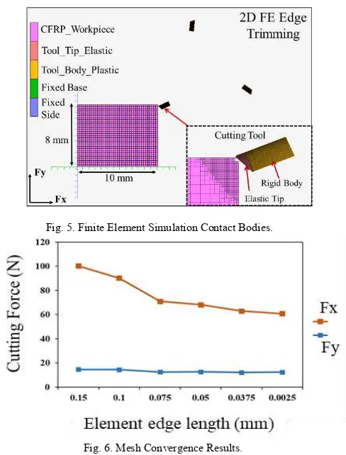
Cutting edge radius has been shown to be the useful indicator of cutting tool wear in CFRP machining and gives an accurate and discrete indication of current cutting tool geometry, unlike flank wear [17]. The various cutting tool edge radii have been implemented by FE mesh at the cutting tool tip, as shown in Fig. 3. and Fig. 4. The cutting edge radius of the cutting tool tip has been increased in 5 µm stages up to 30 µm and the effects of increased cutting tool ageing on cutting forces is predicted. A meshing bias has been used towards the tip of the tool so that there is finer elements in the tool-workpiece contact zone. Four node, solid brick, reduced integration elements have been used for both the workpiece and cutting tool- with full integration. A plane stress workpiece thickness of 6mm was applied. Lagrangian spatial conditions is applied to meshed elements, where this means that the material is fixed to the meshed elements and therefore they will move together and deform with any material displacements. A friction factor of 0.08 has been applied, (as confirmed from the literature in wet conditions), between the CFRP and PCD cutting tool using the coulomb bilinear friction model [18]. The FE workpiece dimensions are shown in Fig. 5.
[image:3.595.39.266.473.695.2]An element size of 0.0025 mm was used for the workpiece elements. Mesh convergence was applied by decreasing element edge length, as shown in Fig. 6, and there was a gradually decreasing trend in the cutting force with reduced element size.
Table 1. Test Parameters
PCD Cutting Tool. 0° Helix 3 Flute
An adaptive re-meshing process has been applied onto the workpiece elements which moves with the cutting tool path, as visualised in Fig.4. A boundary cylinder region around the tool tip is used, so that, any elements which lie within will be subdivided, by a maximum factor of four, to 1/16th of the
original element size. Using re-meshing enabled a further refinement of the CFRP mesh in areas of tool-workpiece contact. The mesh is user-defined to update every tenth increment, thus minimising unnecessary use of computational resources, whereby refining the mesh at the beginning of every increment is the default.
Workpiece contact is initiated using the MSC node to segment option and the contact bodies were defined as shown Fig.5. The cutting tool is the primary contacting body and the workpiece elements are the secondary. This contact method distinguishes the nodes of the cutting tool and surfaces of the workpiece as different contact bodies. The contacting body which is the cutting tool tip must be given a finer mesh, depicted in Fig.5. Contact between the two bodies is initiated when a node of the cutting tool comes within the outside-distance tolerance of the workpiece surface elements. During contact an iterative procedure is used to preserve equilibrium between the two contacting bodies and at the end of each new increment the contact surfaces are updated in case of element deletion or translation. If a node of the cutting tool unexpectedly passes through the inside-distance tolerance of the element then the increment will be split and recycled with a shorter load-step. In this way the simulation ensures that two contact bodies cannot pass through one another. The tool tip is modelled with elastic properties, while the rest of the tool body is given fully rigid properties.
The motion of the cutting tool has been directed using velocity boundary conditions, in the rotational and feed directions, which are equal to those applied in the edge trimming experiment. The cutting forces in the feed direction and thrust direction were then calculated at increasing levels of tool wear. In post-processing, the Hashin damage mode failure index was assessed for different fibre orientations and find the failure modes which had the highest magnitude of CFRP material failure. This was used to verify the different cutting mechanisms on each fibre orientation in an edge trimming process.
[image:4.595.305.549.69.390.2]To control the simulation time step an adaptive convergence control was used. This works by adapting the duration of time for each increment, which depends upon the difficulties of the load-displacement equilibrium equations to converge and is modified according to the number of iterations taken. Thus, if there is a failure of the FE solver to converge -for a particular increment- due to material non-linearity, material failure or new material contact conditions, then the time step will be reduced for the subsequent increment. In an edge trimming operation there is an interrupted variable cutting contact, as the cutting tool rotates, and also a variable chip thickness. This corresponds that during material cutting there will be an intermittent contact between the tool and workpiece elements, and that the cutting tool will cycle in and out of contact with the workpiece. When not in contact, the increment time-step can be extended to increase the tool displacement, (for each increment), and reduce the simulation time. Adaptive load steps have been found to significantly decrease the overall simulation time because the maximum computational
[image:4.595.94.232.71.206.2] [image:4.595.40.277.585.740.2]Fig. 5. Finite Element Simulation Contact Bodies. Fig. 3. Meshed Tool Tip Cutting Edge Radius.
Fig. 4. Local Mesh Refinement
Fig. 6. Mesh Convergence Results.
ful
62 Nicolas Duboust et al. / Procedia CIRP 82 (2019) 59–64
resources are applied only during highly non-linear simulation events, such as element contact and workpiece failure.
Deletion of elements, by material deformation and material failure, was calculated according to the laminate failure strength using the Hashin damage model. After submitting the simulation then the cutting forces parallel to the cutting tool feed direction (Fx) and the thrust force (Fy), which is perpendicular to both the workpiece surface and feed direction, are calculated to find the mean cutting forces.
4. Results
An example of the output cutting force calculated by the FE model, during steady-state depth of cut, is shown in Fig.7. It is shown that the cutting forces fluctuate and this is an effect of the cutting tool rotation, variable chip thickness and material deformation. The mean cutting force (Fx) is calculated from these outputs, and the variation in mean cutting forces have been predicted at increasing 5 µm steps of CER. The mean cutting force from FE were compared with experiment as shown in Fig.8, for a cutting speed of 188.5 m/min and 45° fibre orientation, at two levels of feed rate- 800 and 1200 mm/min. The mean cutting forces have been calculated for 45° and 90° fibre orientations at the cutting speeds feed rates, and CER, as shown by Fig.8-Fig.11.
It was found that increasing feed rate showed an increase in the Fx machining force, in both experiment and FE prediction. This can be explained because using a higher feed rate will increase the chip thickness. The effect of cutting speed was found to be less significant than feed rate. Literature results have also shown that there is an increase in cutting force with increasing feed and that the cutting force also increases with increasing chip thickness [13],[14]. Also, it has been shown that there is an increase in cutting forces with tool wear in FE and experiment, as shown in Fig.8-Fig.11. This is because as the CER increases there will be a larger tool-workpiece contact area, thus there will be greater cutting force and friction, and the cutting mechanism will change to a fibre tearing mechanism. An increase in cutting forces and tool edge rounding has been shown to correlate with a decrease in surface quality and an increase in machining defects [1],[15]. These machining defects may cause failure of parts to conform to manufacturing quality requirements, or a reduction in part integrity, and it is therefore important to assess the consequences of these effects using numerical analysis. The effect of the cutting edge radius increasing from 5 µm to 30 µm has shown a predicted increase in the Fx cutting forces in the range of 50 %. This result shows that cutting edge rounding has a strong effect on machining forces, and that FE has been applied as an analysis tool to calculate the effects of CER on a CFRP machining process.
A difference in the range of -8 % to +28 % was calculated between the FE results and experiment for the new tool condition. Whereas a maximum difference of -50% was found for the worn tool condition. Therefore, the FE model made a closer prediction of cutting forces in the unworn cutting tool condition compared to the worn cutting tool condition. This
[image:5.595.311.563.77.215.2]Fig. 9. Cutting Forces vs Increasing Edge Radius- Feed rate of 800 and 1200 mm/min, (Cutting Speed- 251.3 m/min and 90° Fibre Orientation).
Fig.11. Cutting Forces vs Increasing Edge Radius- Feed rate of 800 and 1200 mm/min, (Cutting Speed- 251.3 m/min and 45° Fibre Orientation). Fig. 10. Cutting Forces vs Increasing Edge Radius- at a Feed Rate of 800 and
[image:5.595.310.572.238.394.2]1200 mm/min, (Cutting Speed- 188.5 m/min, and 45° Fibre Orientation).
[image:5.595.50.285.352.599.2]Fig. 8. Cutting Forces vs Increasing Edge Radius- at a Feed Rate of 800 and 1200 mm/min, (Cutting Speed- 188.5 m/min and 90° Fibre Orientation).
[image:5.595.54.285.632.767.2]may be because in the experimental worn cutting tool condition there is adhesion of fibres to the cutting tool edge (generating greater friction), and higher cutting forces than in the numerically predicted method. The mean effects of each of the parameters calculated by FEM is shown in Fig.12. The significance of each parameter on the Fx machining force were calculated from experiment, using P Values, and it was found that the feed rate and CER had the strongest statistical effect on the Fx cutting force. Increasing feed and CER both had a significant effect on the cutting force. It was also found that the machining forces were not significantly influenced by the effect of fibre orientation.
4.1 Surface Damage Assessment
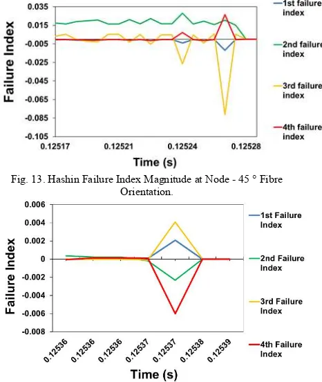
In CFRP machining, the mechanism of material failure- by fibre and matrix damage- is what will determine the fracture mechanism to form a chips and the resulting surface quality. The Hashin damage model has been used to represent the progressive material failure and the relative index of each of the different failure types. Therefore, the magnitude of each of the different failure index during material failure has been quantified to represent the effect of the material fibre orientation and its effect on the cutting mechanism. The relationship between material removal by the cutting edge and fibre orientation has been shown to strongly dictate the damage mechanism and material failure [1]. It was found for the 45 ° fibre orientation that the 3rd failure index, (matrix tension), has
shown the highest magnitude upon material failure, this is followed by the 2nd and 4th failure mechanisms, which are fibre
[image:6.595.40.280.214.365.2]compression and matrix compression respectively, as shown in Fig. 13. It therefore can be interpreted that machining of 45 ° fibre orientation then the cutting tool pushes into the workpiece causing the matrix to crack in tension, and consequently, the reduction in matrix strength will allow the fibres to be bent, crushed and fracture. The magnitude of each of the different failure index is shown in Fig. 14, for machining at the 90 ° fibre orientation with a 10 µm edge radius. It was found that the 4th
failure index has the highest magnitude, followed by the 3rd and
1st- which are matrix compression, matrix tension and fibre
tension respectively. It is therefore reasoned, that localised matrix compressive and matrix tensile damage are precursors to fibre tensile damage and element failure in the 90 ° fibre orientation. The progression of fibre failure in the 90 ° fibre orientation is shown in Fig.15 which shows that the magnitude of damage in the fibre tensile mode increases with node cutting
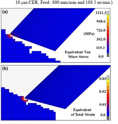
tip contact and is localised near to the tip contact. Shown in Fig.16a is the post-processing of the workpiece surface maximum stress at an individual element node prior to element removal, which shows the magnitude of Equivalent Von Mises stress in the region of 1208 MPa. The maximum tensile strength of the fibres is 4900 MPa in tension and 1860 MPa in compression. In comparison, the matrix strength is 111 MPa and 214 MPa, in tension and compression respectively. The calculated maximum stress is therefore shown to be of a significantly high magnitude to cause matrix failure. Shown in Fig.16b, there is a localised strain at the tool-workpiece interface of 0.03. The CFRP material has a strain to failure of 0.02 and 0.05 for the matrix and fibre, respectively. The localised strain at the workpiece tip is therefore of a magnitude great enough to cause failure of the matrix by strain deformation. The localised damage area and small strain to failure explains the small and dust like chips which are formed during CFRP machining. This damage is represented in experiments by brittle failure mechanism shown by; torn fibres, surface roughness and matrix cracking. The dissimilarity in cutting mechanism and damage mechanism on different fibre orientations is also represented in experiment by variation in surface quality measurements [16]. Confirming this result using FE is valuable because it confirms that the material lay-up will play an important aspect in the cutting mechanism and surface quality. It has been shown that the machining damage, stress, and strain are localised in an area near to the point of contact between tool and workpiece. The brittle failure mechanism of the material, which characterises a lack of plastic deformation, is illustrated by this localised failure and small chip size.
[image:6.595.318.551.470.746.2]Fig. 12. Mean Effects of parameters on Fx.
Fig. 13. Hashin Failure Index Magnitude at Node - 45 ° Fibre Orientation.
64 Nicolas Duboust et al. / Procedia CIRP 82 (2019) 59–64
5. Conclusions
A new FE model has been developed for a CFRP edge trimming operation of a unidirectional laminate. The model has been used to predict the effects of cutting tool ageing on machining forces, and has numerically assessed the magnitude of Hashin model failure mechanisms on different fibre orientations. It has been shown that an experimentally measured cutting edge radius can be used to predict cutting forces in a 2D edge trimming model. It was found that closer prediction of Fx cutting forces was made in the new tool condition than worn. A significant increase in cutting forces was calculated when the cutting edge radius increased from 5 µm to 30 µm- which represents the difference between a new and worn cutting tool. Cutting edge radius and feed rate were found have a more significant effect on the Fx machining force than the cutting speed and fibre orientation. A higher cutting force was seen with an increasing feed rate and a greater chip thickness. In future work then experimental testing should be extended to include a wider range of machining parameters and a cutting tool with a greater magnitude of edge wear. It was found that matrix compressive and tensile failure were the dominant failure mechanism in the 90 and 45 ° fibre orientations and that there was a localised failure in the tool-workpiece contact zone. Also, a localised stress and strain was seen on the material surface prior to element deletion, and a
maximum stress in the range of 1098-1288 MPa was calculated in element nodes prior to material removal. In this research FE modelling has been used to calculate the effects of changing cutting edge radius, cutting speed, fibre orientation and feed rate on the cutting forces in a unidirectional CFRP edge trimming process. Further work can apply these methods to analyse the effects of new cutting tool geometries on machining forces and to develop new numerical prediction tools for the effects of CER on surface roughness parameters.
References
[1] J. Sheikh-Ahmad, Machining of Polymer Composites. Boston, MA: Springer US, 2009.
[2] B. Denkena and D. Biermann, “Cutting edge geometries,” CIRP Ann. - Manuf. Technol., vol. 63, no. 2, pp. 631–653, 2014.
[3] M. Arola, D. Ramulu, “Orthogonal cutting of fiber-reinforced
composites a finite element analysis,” Int. J. Mech. Sci., vol. 39, no. 5, pp. 597–613, 1995.
[4] C. Santiuste, X. Soldani, and M. H. Miguélez, “Machining FEM model of long fiber composites for aeronautical components,” Compos. Struct., vol. 92, no. 3, pp. 691–698, Feb. 2010.
[5] V. A. Phadnis, F. Makhdum, A. Roy, and V. V Silberschmidt, “Drilling
in carbon / epoxy composites : experimental investigations and finite
element implementation,” pp. 1–32, 2012.
[6] L. Lasri, M. Nouari, and M. El Mansori, “Modelling of chip separation
in machining unidirectional FRP composites by stiffness degradation
concept,” Compos. Sci. Technol., vol. 69, no. 5, pp. 684–692, Apr. 2009. [7] K. Giasin, S. Ayvar-Soberanis, T. French, and V. Phadnis, “3D Finite
Element Modelling of Cutting Forces in Drilling Fibre Metal Laminates
and Experimental Hole Quality Analysis,” Appl. Compos. Mater., vol. 24, no. 1, pp. 113–137, 2017.
[8] N. Duboust et al., “2D and 3D Finite Element Models for the Edge Trimming of CFRP,” Procedia CIRP, vol. 58, pp. 233–238, 2017. [9] K. Kerrigan and G. E. O’Donnell, “On the Relationship between Cutting
Temperature and Workpiece Polymer Degradation during CFRP Edge
Trimming,” Procedia CIRP, vol. 55, pp. 170–175, 2016.
[10] X. M. Wang and L. C. Zhang, “An experimental investigation into the orthogonal cutting of unidirectional fibre reinforced plastics,” Int. J. Mach. Tools Manuf., vol. 43, no. 10, pp. 1015–1022, Aug. 2003. [11] J. R. Davis, ASM Speciality Handbook: Tool Materials. ASM
International, 1995.
[12] Z. Hashin, “Failure criteria for unidirectional fiber composites,” J. Appl. Mech., vol. 47, no. June, pp. 329–334, 1980.
[13] A. I. Azmi, R. J. T. Lin, and D. Bhattacharyya, “Machinability study of
glass fibre-reinforced polymer composites during end milling,” Int. J. Adv. Manuf. Technol., vol. 64, no. 1–4, pp. 247–261, Mar. 2012. [14] M. Slamani, J. F. Chatelain, and H. Hamedanianpour, “Influence of
machining parameters on surface quality during high speed edge
trimming of carbon fiber reinforced polymers,” Int. J. Mater. Form., pp. 1–23, 2018.
[15] N. Nguyen-dinh, R. Zitoune, C. Bouvet, and S. Leroux, “Surface
integrity while trimming of composite structures: X-ray tomography
analysis,” Compos. Struct., vol. 210, no. December 2018, pp. 735–746, 2019.
[16] N. Duboust et al., “An optical method for measuring surface roughness
of machined carbon fibre-reinforced plastic composites,” J. Compos. Mater., 2016.
[17] A. Faraz, D. Biermann, and K. Weinert, “Cutting edge rounding: An
innovative tool wear criterion in drilling CFRP composite laminates,”
Int. J. Mach. Tools Manuf., vol. 49, no. 15, pp. 1185–1196, 2009. [18] G. Chardon, O. Klinkova, J. Rech, S. Drapier, and J. Bergheau,
“Characterization of friction properties at the work material / cutting
tool interface during the machining of randomly structured carbon fi bers reinforced polymer with Poly Crystalline Diamond tool under dry
conditions,”Tribiology Int., vol. 81, pp. 300–308, 2015.
Acknowledgements
[image:7.595.63.263.220.430.2]This work was co-funded through the EPSRC Industrial Doctorate Centre in Machining Science (EP/I01800X/1) and by Rolls-Royce whom the authors would like to thank.
Fig. 16. Equivalent Von Mises Stress and Equivalent Total Strain- 10 µm edge radius and 45 degree fibre orientation. Fig. 15. Fibre Tensile Damage Magnitude- (90 ° fibre orientation,