This is a repository copy of
Manipulation Planning Using Environmental Contacts to Keep
Objects Stable under External Forces
.
White Rose Research Online URL for this paper:
http://eprints.whiterose.ac.uk/151146/
Version: Accepted Version
Proceedings Paper:
Chen, L, Figueredo, LFC orcid.org/0000-0002-0759-3000 and Dogar, M
orcid.org/0000-0002-6896-5461 (Accepted: 2019) Manipulation Planning Using
Environmental Contacts to Keep Objects Stable under External Forces. In: Proceedings of
2019 IEEE-RAS International Conference on Humanoid Robots. 2019 IEEE-RAS
International Conference on Humanoid Robots, 15-17 Oct 2019, Toronto, Canada. IEEE .
(In Press)
This paper is protected by copyright. This is an author produced version of a paper
accepted for publication in Proceedings of 2019 IEEE-RAS International Conference on
Humanoid Robots. Personal use of this material is permitted. Permission from IEEE must
be obtained for all other uses, in any current or future media, including
reprinting/republishing this material for advertising or promotional purposes, creating new
collective works, for resale or redistribution to servers or lists, or reuse of any copyrighted
component of this work in other works. Uploaded in accordance with the publisher's
self-archiving policy.
[email protected] https://eprints.whiterose.ac.uk/
Reuse
Items deposited in White Rose Research Online are protected by copyright, with all rights reserved unless indicated otherwise. They may be downloaded and/or printed for private study, or other acts as permitted by national copyright laws. The publisher or other rights holders may allow further reproduction and re-use of the full text version. This is indicated by the licence information on the White Rose Research Online record for the item.
Takedown
If you consider content in White Rose Research Online to be in breach of UK law, please notify us by
Manipulation Planning Using Environmental Contacts
to Keep Objects Stable under External Forces
Lipeng Chen, Luis F. C. Figueredo, Mehmet Dogar
Abstract— This paper addresses the problem of sequential
manipulation planning to keep an object stable under chang-ing external forces. Particularly, we focus on uschang-ing object-environment contacts. We present a planning algorithm which can generate robot configurations and motions to intelligently use object-environment, as well as object-robot, contacts, to keep an object stable under forceful operations such as drilling and cutting. Given a sequence of external forces, the planner minimizes the number of different configurations used to keep the object stable. An important computational bottleneck in this algorithm is due to the static stability analysis of a large num-ber of configurations. We propose a containment relationship between configurations, to prune the stability checking process.
I. INTRODUCTION
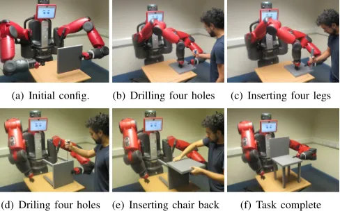
We propose an approach to address manipulation planning of keeping an object stable under a sequence of chang-ing external forces. Particularly, we focus on uschang-ing object-environment contacts, in addition to using robot grasps. Take the example in Fig. 1, where a human and a robot collaborate to assemble a chair. Throughout the assembly task, the human applies changing forces on the chair pieces, due to a sequence of drilling and inserting operations. The robot is supposed to assist the human by keeping the chair assembly stable as these forceful operations are applied. The robot itself cannot to hold the chair assembly stable against all the different and large external forces. Nevertheless, by exploiting object contacts with the environment (e.g. the table surface in Fig. 1), as well as object contacts with the robot (e.g. grasps, or griper pressing as shown in Fig. 1(b)-1(c)), the robot succeeds in stabilizing the object under the sequential changing forces.
The problem of regrasp planning with environmental sup-port/contact has been well explored before [1], [2], [3], [4], [5], while planning to resist changing external forces applied onto an object using environment contacts remains to be studied, to the best of our knowledge. In our previous work [6], we describe a robot grasping an object to resist external forces but without using the object contacts with the environment, which is our focus in this current work. Motivated by the potential of exploiting environmental con-tacts, for example in a human-robot collaborative task as shown in Fig. 1, we propose a novel planning approach that enables the robot to use both the environment’s and robot’s stabilization capabilities in manipulating an object under
This project has received funding from the European Union’s Horizon 2020 research and innovation programme under the Marie Sklodowska-Curie grants agreement No. 746143 and 795714, and from the UK Engi-neering and Physical Sciences Research Council under grant EP/P019560/1. Authors are with School of Computing, University of Leeds, Leeds, UK,
{sclc, l.figueredo, m.r.dogar}@leeds.ac.uk
(a) Initial config. (b) Drilling four holes (c) Inserting four legs
[image:2.612.316.560.158.310.2](d) Driling four holes (e) Inserting chair back (f) Task complete
Fig. 1. The robot holds the chair pieces stable under sequential force-demanding operations in an assembly task, by exploiting object contacts with both environment (e.g. a table surface) and robot (pressing or grasping).
changing external forces and integrate them with intelligent motion planning.
To achieve robust and efficient manipulation, our planner addresses three main challenges. First, the planner identifies appropriate object contacts with the environment and/or the robot, relying on which the object can stay stable under forceful operations. This requires the planner to determine
whereto move and position the object w.r.t. the environment and robot. For example, at the configuration in Fig. 1(b), the object-table contact and object-robot contact (the gripper pressing) can together stabilize the chair piece under the drilling forces. Second, to improve manipulation efficiency, the planner reasons over a large number of available contact configurations for an optimal solution, which requires mini-mal number of contact adjustments and thus robot motions during manipulation. For example, in Fig. 1, in total, there are only two different configurations (Fig. 1(b) and 1(d)) and thus one contact change during assembling. This requires the planner to decide onwhento change the object pose w.r.t. the environment and robot as the operations are applied. Finally, for each change in the object contacts, the planner needs to decide onhowto move the object to implement the change, e.g. from the one in Fig. 1(c) to the one in Fig. 1(d).
A key source of computational cost of the planner comes from stability checking: the planner samples a large set of candidate configurations, with a wide variety of object-environment and object-robot contacts. Each such configura-tion needs to be checked for stability against possible exter-nal forces. Given frictioexter-nal constraints at the contact points, such a stability checking takes the form of a constrained optimization problem, a computationally expensive process. Therefore, as another contribution, we propose a novel strategy to efficiently perform stability checking of a large number of configurations. We introduce a concept of con-tainment among contact configurations. Given two contact configuration, based on their object contacts with the envi-ronment and robot, we say one configuration contains the other, if the stability of the latter against an external force implies the stability of the former. For instance, a bimanual grasp containsits both individual grasps. By exploiting this concept, the planner can easily compare the stabilization capabilities among different contact configurations and thus quickly prune the list of candidates. We provide details of the containment-based stability checking in Sec. IV.
We show the performance of our planner and the containment-based stability checking in Sec. V. We show our planner can produce effective manipulation plans with reduced number of configuration changes in comparison with baseline planners. We present the containment-based stability checking brings in almost an order of magnitude improve-ment in planning speed compared with a naive approach.
A. Previous Work
The idea of exploiting structures in the environment via physical contacts can be traced in the earliest approaches for compliant fine motion generation [7]. Evidence of com-plex interaction between multi-step manipulation planning problems and a shared environment is also found in [1], [2], which addressed structures in the shared environment as obstacles to be avoided while manipulating target objects. Recently, planners have been proposed to use structures in the shared environment as extra supports for various manipulation tasks like grasping [8], [9] regrasping [3], [5], prehensile [10], [11] and non-prehensile manipulation [12]. A similar multi-step planning problem is studied by Bretl [13], to produce contact modes for a spider robot climbing a wall. We use a similar hierarchical approach, but focus on the problem where there are changing external forces applied onto the manipulated objects.
Our novel contributions in this work include:
1) A planning framework that exploits both the object-environment contacts and the object-robot contacts to resist changing external forces with a minimal number of configuration changes—ensuring a more smooth and efficient manipulation;
2) The formulation of the containment relations among different contact configurations to perform efficient static stability checking;
3) Real robot and simulated experiments illustrating the effectiveness and efficiency of the planning framework.
A forceful operation example:F1
F1
F2
F5
F7
F14
F20
f
p f1
p1
[image:3.612.321.559.51.157.2]A forceful task example:{Fi}20i=1
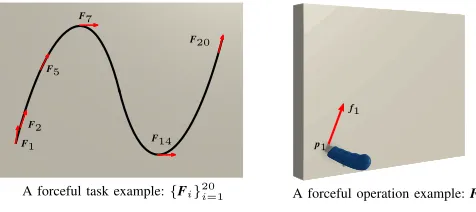
Fig. 2. A forceful task consists of a sequence of forceful operations.
II. PROBLEMFORMULATION
We are interested in building a planner that enables a robot to efficiently manipulate an object under the application of sequential or changing forceful operations, e.g. drilling, cutting and peg inserting.
We refer to a forceful task as a complete sequence of operations to be applied onto an object, for example, the chair assembly task in Fig. 1. We give another example in Fig. 2, where the task is cutting a wave-shaped curve on a board. We refer to a forcefuloperationas a single step of a forceful task. For example, in Fig. 1, each involved assembling action (e.g. drilling) is a separate forceful operation. For tasks consisting of a continuous application of forces over time, we divide into a sequence of operations via discretization, e.g. the 20 discrete cutting operations in Fig. 2.
We model a forceful operationFas a 6Dgeneralizedforce (force/torque) f w.r.t. a tool frame and its application pose p w.r.t. the target object (Fig. 2-Right), and thus denote a forceful task as:
{Fi} m
i=1={(fi, pi)} m
i=1 (1)
wheremindicates the number of involved operations. We formulate the problem by explicitly exploiting the object contacts with both the environment and robot. Specif-ically, herein we assume the robot can contact an object by
pressing (e.g. the robot’s right hand in Fig. 1(b) and 1(c)) or grasping (e.g. the robot’s left hand in Fig. 1), while the environment includes rigid structures which allow an object to be in contact with, e.g. the table surface in Fig. 1. During a forceful task, the environmental and robot contacts together provide supporting wrenches to manipulate and stabilize the object under forceful operations.
Throughout this work, we assume the forceful task and the geometric model of the system are given. Other physical parameters, including object mass, centre of gravity and friction coefficients are specified. We denote the composite system configuration asq= (qr, qo), whereqr∈R
nrdenotes
configuration of robot manipulators (nr is the total DoFs of manipulators) andqo∈SE(3)denotes object pose. A system configurationqspecifies a set of environmental and/or robot contacts onto the target object, by which the environment and robot generate reaction forces capable of moving and stabilizing the object against gravity and external forces.
A. Overview of Problem
Environ. contactCe Robot contactCr
q1 q2 q3
q0
t1 t2 t3
CuttingF1toF7 CuttingF8toF14 CuttingF15toF20
F1
F7 F8
F14
F15
[image:4.612.67.552.50.135.2]F20
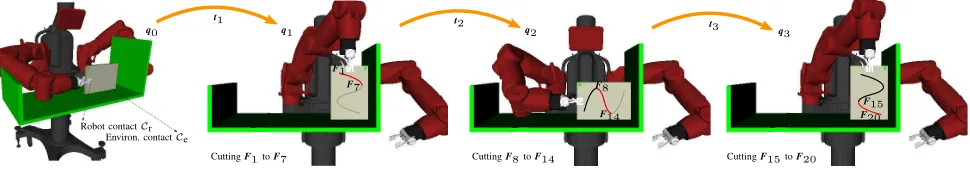
Fig. 3. The planner generates a minimum sequence of system configurations
qj
3
j=1to keep the object stable under{Fi} 20
i=1 and a sequence of
trajectories{tj}3j=1to move the object to go through the planned configurations.
Given a single forceful operation F, finding a system configuration q that can keep the object stable requires 1) first finding a kinematically valid configuration q; 2) then checking if the environment and robot can provide sufficient resultant wrenches via physical contacts to keep the object stable. We refer to this problem as stability checking and explain in detail how we address it in Sec. IV-A.
Then, given a sequence of forceful operations {Fi} m i=1, i.e. a complete task, the most straightforward solution would be to find one feasible configurationqfor a given operation Fi and hold such configuration until it is no longer stable for a new incoming oneFi+, where i+>i. However, such a
strategy, would require the robot and object to use a large sequence of different system configurations and accordingly configuration transfers during manipulation. Herein, we refer to such a configuration transfer as a configuration change.
Alternatively, to avoid frequent task interruptions due to configuration changes, the robot can reason about the system configurations to make the utmost of one configuration q against a larger sequence of forceful operations, which in turn would reduce the number of configuration changes. This,
configuration change minimization, imposes an additional but practically necessary requirement for efficient and smooth manipulation. In this work, we explicitly address this as a main objective, building a planning framework that mini-mizes the sequence of system configurations while satisfying the sequential forceful constraints. In Sec. III, we introduce a planner that generates such efficient sequences based on the assessment of a set of stable system configurations, while in Sec. IV, we present how this assessment can be performed efficiently by exploiting theircontact-containmentrelations.
B. Definition of Sequence of Stable Configurations
We say a system configuration q is stable against a se-quence ofkforceful operations{Fi}
k
i=1, if the environmental and robot contacts at the configurationqare able to provide sufficient wrenches to keep the object stable under any forceful operation in{Fi}
k i=1.
Further, we say that a sequence of system configurations
qj n
j=1 is stable against a sequence of forceful operations
{Fi}mi=1, if the configurations in
qj
n
j=1 cover all opera-tions in {Fi}
m
i=1 in order, i.e., ifq1 is stable against oper-ations {F1,F2, ...,Fk}, and q2 is stable against operations
{Fk+1,Fk+2, ...,Fl}, and so on, until qn is stable against operations {Fw+1,Fw+2, ...,Fm}, where 1 ≤ k ≤ l ≤
... ≤ w ≤ m. For example, in Fig. 3, the three system
configurations{q1,q2,q3}cover 20 cutting operation:q1is stable against the cutting operations F1 toF7; q2 is stable against the cutting operationsF8toF14;q3 is stable against the cutting operationsF15toF20. In this sense, configuration change minimization can be achieved by finding a minimal sequence of configurations
qj n
j=1 stable against{Fi}
m i=1. In addition to minimizing the number of configuration changes, the robot also needs to move the object to go through the planned configurations inqj
n
j=1 in order, us-ing collision-free and stable trajectories{tj}nj=1. Specifically, each trajectory tj moves the system from qj−1 to qj ( q0 is the initial system configuration), which corresponds to a constrained motion planning. For example, in Fig. 3, the three orange lines illustrate such trajectories{t1, t2,t3}.
In this context, given a sequence of forceful operations
{Fi} m
i=1 and an initial system configuration q0, our prob-lem can be stated as finding a minimum sequence of system/contact configurations qj
n
j=1 and its connecting trajectories {tj}
n
j=1 to move and stabilize the object under the application of sequential forceful operations{Fi}
m i=1.
III. PLANNINGAPPROACH
This section presents details of our planning framework.
A. Manipulation Planning Using Operation Graph
Our planner takes a hierarchical framework. At the high-level it builds and searches what we call anoperation graph
for a minimal sequence of configurations qj n
j=1 that are stable against{Fi}
m
i=1. It then generates motion trajectories
{tj} n
j=1to connect these planned configurations. We provide pseudo-code of the planner in Alg. 1.
1) Building the Operation Graph: The planner starts by building a directed acyclic weighted graph, referred to as the operation graph, using checked-stable configurations from among a set of sampled candidate configurationsQs.
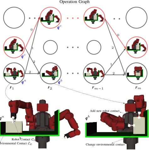
Specifically, as illustrated in Fig. 4, in an operation graph, the ith column corresponds to the ith operation Fi, while all nodes in the ith column represent a subset of sampled configurations in Qs, which are checked stable against Fi (We present how this check is performed in Sec. IV-A).
F1 F2 Fm−1 Fm
2 0
0
2
1 2
Operation Graph
Environmental ContactCe Robot ContactCr
Add new robot contact
Change environmental contact
qa qb
qa
1
2
qb
qc
[image:5.612.58.295.49.288.2]qc
Fig. 4. We build an operation graph to search for efficient solutions.
2) Weighting Links in Operation Graph: As illustrated in Fig 4, rather than weighting the link of two different configurations (e.g., from qa to qb) as 1, here we adopt a more detailed weighting scheme, computing the weight as the number of the total changes in both environmental and robot contacts. For example, in Fig. 4, from the node qa in the first column to the nodeqb in the second column, we say the number of configuration changes is 2, including one robot contact change (one extra gripper is added onto the object) and one environmental contact change (the contact region changes). However, the weight between the node qc in the first column and the nodeqc in the second column is set to be 0, since they simply represent the same configuration.
3) Searching the Operation Graph: At this point, using the operation graph, finding a minimal sequence of system configurations qj
n
j=1 stable against {Fi}
m
i=1 is reformu-lated as a graph search problem. The expected output is a path that starts from one node in the leftmost column for operation F1 and ends with a node in the rightmost column for operation Fm, with the smallest total weight. By searching the graph, e.g., using the Dijkstra’s algorithm, the planner can easily get optimal solutions, i.e. efficient manipulation plans with a minimal number of configuration changes. In Fig. 4, the red path illustrates such a solution.
The procedure PlanStableSequence in Alg. 1 provides the pseudo-code of planning using the operation graph. The procedure BuildOperationGraph builds the operation graph (line 2) as outlined above. The procedure GraphSearch (line 3) searches the operation graph to generate a candidate configuration sequence qj
n
j=1. Then for every two sub-sequent pair of configurations in the sequence (line 5 - 9), the procedure PlanConfigChange attempts to plan motions via general motion planners, e.g. RRT-based planners, to implement the configuration changes.
4) Finding Stable Configurations for An Operation: As described above, building an operation graph requires the
Algorithm 1Manipulation Planning Using Operation Graph
PlanStableSequence {Fi}m i=1,q0
:
1: Qs←Generate a set of candidate system configurations 2: GO←BuildOperationGraph {Fi}mi=1, Qs
3: qj n
j=1←GraphSearch(GO)
4: qj n
j=0←Addq0 to the beginning of
qj n
j=1
5: foreach subsequentqjandqj+1 in
qj n
j=0do
6: tj+1←PlanConfigChange(qj,qj+1)
7: ifPlanConfigChange failedthen 8: Remove failing edge from graphGO
9: Go to line 3
10: return(
qj n
j=1,{tj}
n j=1)
BuildOperationGraph {Fi}m i=1, Qs
: 1: GO← ∅
2: foreach forceful operationFi in{Fi}m i=1 do
3: S←FindStableConfigs(Fi, Qs) 4: ifi= 1 then
5: AddS intoGO as the first column
6: else
7: foreach configurationq′ in previous column ofG O do 8: foreach configurationq′′inS do
9: w←ComputeWeight(q′,q′′)
10: Create a link fromq′ toq′′with a weightw 11: returnGO
planner to check and find a subset of stable configurations for each forceful operation in{Fi}
m
i=1, from a set of sampled candidate configurationsQs. This is achieved by FindStable-Configs in Alg. 1 (line 3 in BuildOperationGraph).
The planner starts from sampling a set of candidate configurations Qs, which acts as a representative to the high-dimensional composite configuration space (line 1 in PlanStableSequence). The setQsincludes a variety of config-urations with different object-environment and object-robot contacts. Given an object and an environment model, the problem of contact generation with the environment has been extensively studied in the literature based on geometric computation [14], [15], learning [16] and kinematics simu-lators [17], [5]. Likewise, robot-object contacts can be com-puted via general grasp planners, e.g. Miller and Allen [18]. Such techniques lie outside the scope of this work. Our planner is, in fact, agnostic to the contact generation strategy and thus can take any existing method in the literature for this step. In Sec. V, we explain how we generated such sets of candidate configurations for our experimental studies.
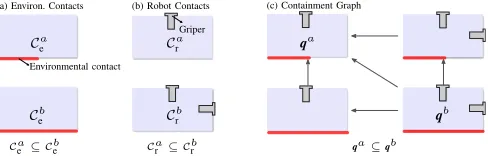
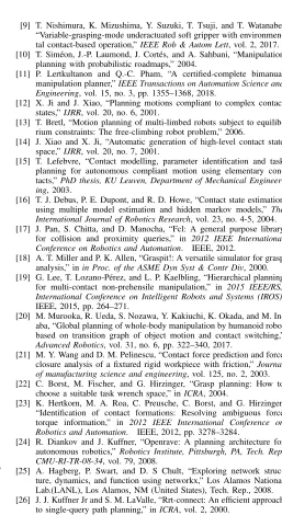
Cae ⊆ Cbe Cra⊆ Cbr qa⊆qb
Ca
e
Cb
e
Ca
r
Cb
r
qa
qb
(c) Containment Graph (a) Environ. Contacts (b) Robot Contacts
Griper
Environmental contact
Fig. 5. We build a containment graph over all system configurations inQs to represent their containments. The red segments illustrate environmental contacts with the object.
IV. STABILITYCHECKING
In this section, we formulate the stability checking of a system configurationq against a forceful operation Fas an optimization problem. Then, we present an approach that can efficiently find all configurations inQsthat are stable against F, i.e. the procedure FindStableConfigs in Alg. 1.
A. Stability Checking for A Single Forceful Operation
Stability checking refers to the problem of assessing if a system configurationqis able to provide sufficient wrenches to stabilize an object under a forceful operationF.
As illustrated in Fig 5, under the assumption of rigid bodies, both environmental and robot contacts specify con-tact regions on the object surface (denoted as Ce and Cr respectively), which can be further represented as a set of point contacts. At each contact point, the contact force fc
applied to the object is constrained within a generalized friction conefc∈FC(n, µ)characterized by a contact normal
n and a friction coefficientµ.
Given a forceful operationF=(f, p), and a configuration q consisting of nc point contacts in total (including the uniformly discretized surfaces of both the environmental con-tacts and robot concon-tacts), stability checking requires finding a distribution of contact forces h = [fTc,1, fTc,2, ..., fTc,nc]T, such that:
1) The resultant wrench provided by h is able to keep the object stable, i.e. in static equilibrium, against the external forcef by the operationF;
2) The contact forcesh lie within the composite friction cone H=FC1×...×FCnc.
Therefore, similar to [19], [20], [21], we formulate the problem of stability checking as a constrained optimization problem, particularly a quadratic programming:
min
h∈H h T
h (2a)
s.t. Gh+hmg+R(p)f= 0 (2b)
h∈H (2c)
where G=[G1, ...,Gnp] is a 6 ×6nc matrix mapping the
contact wrenches to a resultant wrench onto the object.hmg is the wrench incurred by object gravity.R(p)transforms the external wrenchf from the tool frame to a common frame.
For a candidate configuration q and an operation F, if we can find a solution hsatisfying the constraints in Eq. 2, we say that the configuration q is able to stabilize the object against the operation F. Otherwise, we say that the configurationqcannot be stable against the operationF. The constraints Eq. 2(b)-2(c) ensure that there exists a distribution
Algorithm 2 Naive Stability Checking
FindStableConfigs(F, Qs): 1: S=∅
2: foreach configurationqin Qs do
3: Solve the constrained optimization problem in Eq. 2 4: ifEq. 2 has a solutionthen
5: AddqtoS
6: returnS
of contact forces h that can keep the object stable under the operationF, while optimizing the objective in Eq. 2(a) ensureshto be close to the actual force distribution [21].
In the following sections, we present two approaches to implement the procedure FindStableConfigs in Alg. 1, which performs stability checkings over a large set of sampled configurations inQs.
B. Naive Stability Checking of Qs
Eq. 2 enables the planner to check whether a configuration q is stable against a forceful operation F. Accordingly, given a forceful operation F, the planner can implement the procedure FindStableConfigs by simply performing a separate stability checking via optimizing in Eq. 2, for each candidate configuration inQs.
We call this implementation the naive stability checking. Alg. 2 provides the pseudo-code of this implementation.
Nonetheless, as aforementioned, due to the large set Qs, this implementation can be computationally expensive, and therefore degrade the planing efficiency, as we show with experimental results in Sec. V-B.
C. Containment-Based Stability Checking ofQs
Rather than performing excessive stability checkings by solving optimization problems in Eq. 2 over all configura-tions in Qs, we propose a containment-based approach to implement the procedure FindStableConfigs efficiently. The algorithm relies on thecontainment relationshipamong dif-ferent configurations to quickly eliminate redundant stability checkings. Alg. 3 presents the pseudo-code of this strategy.
1) Containment Relationship: We define the containment relationship between two different system configurations over their capability of resisting external wrenches, i.e. contact wrench space [22], [23]. A system configuration q specifies the geometric relationships among the object, robot and environment, while its corresponding contact region(s) qualitatively indicates its capability of resisting external forces that can be applied on the object. For example in Fig. 51, since the environmental contact region Cb
e contains
Ca
e and the robot contact Crb contains Car, one can say any forceful operation resistible to qa is also resistible to qb. That is,qb containsqain terms of the capability of resisting possible external wrenches. In this context, we define the containment relationship (denoted with ⊆) among different contact configurations as:
Definition 1. Let qa and qb be two system configurations,
we sayqb containsqa (qa⊆qb), iff
1Fig. 5 is illustrated in 2D for clarity of presentation. In our
[image:6.612.56.300.48.126.2] [image:6.612.312.553.61.137.2]• Cea⊆ Ceb and
• Cra⊆ Crb
Note that the containment among the environmental con-tact regions holds only for the same surface concon-tacts, as the friction coefficients may be different for different materials.
2) Containment Graph: We then build an directed acyclic containment graph over all sampled configurations in Qs to represent their containments (line 2 in Alg. 3).
Specifically, as illustrated in Fig. 5(c), each node in the graph represents a candidate configurationqinQs. For every two nodes, if there exists a containment between them as stated in Def. 1, they are connected in the graph with a directed path, e.g. in Fig. 5(c), the nodeqa is contained and thus becomes a successor to the other three nodes.
3) Stability Checking Using Containment Graph: Based on the characteristics of the containment graph, we introduce two properties to simplify the procedure FindStableConfigs.
Property 1. Given a forceful operationFand a containment graph T, if a node q is stable against F, then all its predecessors inT are stable against the operationF.
The property can be easily proved by Def. 1. We call this property the ‘activating’ property, as using this property, if a configuration q is checked to be stable against a forceful operationF, all its predecessor configurations can be directly ‘activated’ as feasible without solving optimization problems in Eq. 2 (line 6-9 in Alg. 3). For example, ifqa
in Fig. 5(c) is stable against an operation F, then all other nodes in the graph can be directly regarded as stable againstF.
Property 2. Given a forceful operationFand a containment graph T, if a node q is not stable against F, then all its successors inT are not stable against the operation F.
Similarly, the property can be easily proved by Def. 1. We call this property the ‘blocking’ property, as using it, if a configurationqis checked as not stable against a forceful operation F, all its successor configurations can be directly ‘blocked’ (line 10-12 in Alg. 3) from searching. For instance in Fig. 5(c), if qb is not able to keep the object against an operationF, then all other nodes in the graph can be directly regarded as infeasible without additional checking.
By exploiting the activating property and blocking prop-erty, the planner needs not to solve a constrained optimiza-tion problem for each configuraoptimiza-tion in Qs separately, thus reducing computational complexity of the procedure Find-StableConfigs greatly. We proposed experiments to verify the effectiveness of using the containment graph in Sec. V-B.
V. IMPLEMENTATION ANDRESULTS
This section presents a variety of simulated and real robot experiments, using a Baxter robot in both cases, to validate and quantitatively assess the performance of our planner.
Experimental Settings: We implemented the planner in OpenRAVE [24] with the flexible collision library (FCL) [17] for collision check and contact detection. We used Scipy.optimize library for the optimization based stability checking (Eq. 2), NetworkX [25] for graph construction
Algorithm 3 Containment-Based Stability Checking
FindStableConfigs(F, Qs): 1: S← ∅
2: T ←Build a containment graph as Fig. 5 3: whileT is not emptydo
4: q←Randomly pick a configuration inT
5: Solve the constrained optimization problem in Eq. 2 6: ifEq. 2 has a solutionthen
7: S←Addqand its predecessors inT intoS 8: T ←Remove qand its predecessors fromT
9: go to line 3
10: else
11: T ←Remove qand its successors fromT
12: Go to line 3
13: returnS
and search, and BiRRT [26] as the motion planner for the procedure PlanConfigChange in Alg. 1.
We implemented the planner on three types of forceful operations. To obtain a more realistic representation, we implemented these operations multiple times on a foam board used as the target object, and measured the operation forces via a force/torque sensor (FT150 from Robotiq). For each type of operations, we took a maximum operation force:
• Adrillingoperation yields a maximum20N force; • Acuttingoperation yields a maximum45N force;
• Aninserting operation yields a maximum16N force.
Generating a Set of Candidate Configurations Qs: We
sampled three sets of candidate system configurations (line 1 of PlanStableSequence in Alg. 1) and fed them to the planner. To obtain such sets with higher sample variety, we evenly discretized and generated a set of contact regions Ce on the object surface with a fixed step size for environmental contacts, and discretized the object surface as a set of contact pointsCr for robot contacts. A combination (Ce,Cr)of such an environmental and robot contact regions defines a contact profile a system configuration q may have. Then, to map the contact regions (Ce,Cr) into a fully-assigned system configurationq, we evenly discretized the structure surfaces in the environment into a set of placement positions. At each position, we checked whether there exists a kinematically valid configurationq meeting the contact profile (Ce,Cr).
In this manner, we sampled three sets of candidate con-figurations with different set size (|Qs|=144,560,1172) for following experimental studies.
A. Analysis of Minimizing Configuration Changes
We first assessed the performance of our planner in min-imizing the number of configuration changes (consequently, task interruptions) along four different forceful tasks:
• Task 1: A rectangular cutting task consisting of 20 continuous cuttings as shown in Fig. 6. The environment has a flat surface in the front of the robot;
• Task 2: A stool fabricating task involving cutting four legs (discretized as twenty cuttings), drilling four holes and inserting four legs (thus a sequence of 28 forceful operations in total) as shown in Fig. 7. The environment has an L-shaped structure;
TABLE I
NUMBERS OF CONFIG.CHANGES FOR EACH TASK BY THE BASELINE
AND PROPOSED PLANNER WITH THREE SIZES OF SAMPLE SETS.
Method |Qs| # of Configuration Changes Task 1 Task 2 Task 3 Task 4
Baseline 144 23 19 20 27
Proposed
144 4 10 7 9
560 3 4 3 3
1172 3 1 1 2
hole-drillings and then four peg-insertings (thus a se-quence of 20 forceful operations in total) as shown in Fig. 1. The environment has a flat supporting surface; • Task 4: A wave cutting task discretized into 20 cuttings
as shown in Fig. 3. The environment has a ⊔-shaped supporting structure.
To the best of our knowledge, there exists no planner in the literature directly capable of solving such complex tasks. Existing strategies would, in the best scenario, need to plan each forceful operation individually, neglecting the sequential property that defines a task. We define such a scenario as the baseline planner. For each operation in a task, the baseline planner iterates over the available candidate configurations in Qs until it finds the first stable one.
Table I summarizes the results of configuration changes by the baseline planner and our proposed planner. As shown in the table, compared with the baseline planner, our planner reduces the number of configuration changes dramatically. Specifically, with |Qs|=144, for Task 1 (the rectangular cutting task), the baseline planner finds a solution with 23
configuration changes and therefore almost generates a new configuration for each involved operation (20 operations in total). Our planner generates a more efficient solution (Fig. 6-Left, Solution A), which involves only 4 different system configurations and4configuration changes in total. Similarly, Fig. 7 shows a solution generated by our planner for Task 2, which involves only 1 configuration change. Fig. 1 and 3 show an efficient solution for Task 3 and 4 respectively.
It is also notable that as we increase the number of sampled configurations in Qs, i.e. the set size |Qs|, the planner may come up with better solutions, that is, manipu-lation plans with a further reduced number of configuration changes, as shown in Table I for all tasks. To better illustrate the difference, take for instance Fig. 6-Right which shows a different solution for Task 1 generated by our planner but with |Qs|=1172. As shown, when the set size |Qs| increased, the planner came up with a more efficient solution: in Solution A (real robot experiments), the planner requires a regrasping (from right arm inq2to left arm inq3) whereas in Solution B (from the simulator)2 the robot is capable to perform the task only with the right hand.
B. Analysis of Planning Efficiency
We further verified the performance of our planner in terms of time efficiency. More specifically, we compared
2Note both scenarios were implemented in simulation and in the real
robot, yet they are presented separately in Fig. 6 to aid the discussion.
q1 q2
Four leg-cuttings Four hole-drillings Four leg-insertings
q2
Fig. 7. A manipulation plan for the stool fabricating task (Task 2) involving 28 operations. The solution contains 1 configuration change (environmental contact fromq1toq2).
our planner (Alg. 1) using the naive stability checking in Alg. 2 (Plan-N, for brevity) with the (same) planner but using the containment-based strategy in Alg. 3 (Plan-Cont, for brevity)3. Note that the two planners differ in the strategy of implementing the procedure FindStableConfigs in Alg. 1, i.e. building the operation graph which is the most computationally complex procedure in Alg. 1, as it involves perform stability checkings over all forceful operations and candidate configurations.
Taking the same four tasks as previous, Table II summa-rizes the average time of building the operation graph over 50 runs for each task, with thetotal planning time listed in parentheses. As shown, the containment-based strategy (bold in Table II) increases the planning efficiency significantly. For example, for Task 2 with |Qs| = 1172, it takes about
2087.8s for the Plan-N to build the operation graph compared to135.8s by the containment-based planner (an improvement of about 15×). Similar analysis can also be made for the other three tasks and configuration sets.
Table II also highlights the time cost of building the operation graph in the total planning time (in parentheses). As shown in the Table, with lower values of|Qs|, i.e. smaller configuration sets, the planner would generate solutions with more configuration changes, and therefore more motion planning iterations would be required. This results in a larger difference between the time of building the operation graph and the total planning time.
It is also important to mention that the containment-based planner requires extra construction of the containment graph as described in Sec. IV-C. Nonetheless, this is a low computational complexity task as illustrated in Table III, which shows the average time of building the containment graph over 50 runs for each task. As shown, the time of building the containment graph increases proportionally to
|Qs|, yet it still represents less than 1% of the building time required for the operation graph in Table II and thus negligible in the overall planning. For example, for Task 2 with|Qs|= 1172, it takes only1.05s for the planner to build the containment graph, but 135.8s to build the operation graph and138.2s for total planning.
Based on above analysis, we can conclude that compared with performing naive stability checkings (Eq. 2) for all oper-ations and sampled configuroper-ations, building the containment graph can greatly improve planning efficiency.
3In Sec. V-A, the proposed planner refers to Plan-Cont, yet both strategies
Solution A SolutionB
[image:9.612.299.556.264.734.2]q1 q2 q3 q4 q1 q2 q3 q4
Fig. 6. Two manipulation plans for the rectangular cutting task (Task 1) consisting of 20 operations. Left: Solution A contains 4 configuration changes, with a robot regrasp (from left arm inq2 to right arm inq3). Right: Solution B contains 3 configuration changes.
TABLE II
AVERAGE TIME(S)OF BUILDING THE OPERATION GRAPH AND THE OVERALL PLANNING TIME IN PARENTHESES FOR EACH TASK OVER50RUNS.
|Qs| Task 1 Task 2 Task 3 Task 4
Plan-N Plan-Cont Plan-N Plan-Cont Plan-N Plan-Cont Plan-N Plan-Cont
144 198.5(223.1) 20.1(37.7) 280.1(335.0) 31.0(81.9) 211.8 (246.8) 22.9(56.7) 201.3(256.1) 22.2(74.6) 560 773.2(792.0) 69.7(86.6) 1100.6(1121.1) 77.8(96.0) 821.5(837.5) 72.4(87.9) 799.1(820.0) 70.8(91.3) 1172 1551.2(1570.1) 98.3(115.4) 2087.8(2092.5) 135.8(138.2) 1611.7(1615.4) 112.0(115.8) 1605.4(1616.7) 109.9(120.0)
TABLE III
AVERAGE TIME(S)OF BUILDING THE CONTAINMENT GRAPH.
|Qs| Task 1 Task 2 Task 3 Task 4
144 0.04 0.06 0.04 0.07
560 0.26 0.40 0.31 0.59
1172 0.97 1.25 1.05 1.52
VI. CONCLUSION ANDFUTUREWORK
We presented a manipulation planning approach to keep an object stable under sequential external forces by utilizing both environmental and robot contacts. The proposed plan-ning strategy fills the gap in sequential manipulation planplan-ning literature, increasing the aptitude of robots to perform com-plex tasks efficiently. Indeed, the proposed solution not only reasons about possible object-environment and object-robot contacts during planning, but also addresses the dimension-ality and combinatorial explosion for the stability checking procedure in an efficient manner through the introduction of a new concept of wrench based containment relationship between configurations.
REFERENCES
[1] T. Lozano-P´erez, J. Jones, E. Mazer, P. O’Donnell, W. Grimson, P. Tournassoud, and A. Lanusse, “Handey: A robot system that recognizes, plans, and manipulates,” 1987.
[2] P. Tournassoud, T. Lozano-P´erez, and E. Mazer, “Regrasping,” 1987. [3] W. Wan and K. Harada, “Developing and comparing single-arm and
dual-arm regrasp,”RA-L, 2016.
[4] N. Chavan-Dafle and A. Rodriguez, “Sampling-based planning of in-hand manipulation with external pushes,” inISRR, 2017.
[5] J. Ma, W. Wan, K. Harada, Q. Zhu, and H. Liu, “Regrasp planning using stable object poses supported by complex structures,” IEEE Transactions on Cognitive and Developmental Systems, 2018. [6] L. Chen, L. F. Figueredo, and M. Dogar, “Manipulation planning under
changing external forces,” in2018 IEEE/RSJ International Conference on Intelligent Robots and Systems (IROS). IEEE, 2018, pp. 3503– 3510.
[7] T. Lozano-Perez, M. T. Mason, and R. H. Taylor, “Automatic synthesis of fine-motion strategies for robots,” The International Journal of Robotics Research, vol. 3, no. 1, pp. 3–24, 1984.
[8] C. Eppner, R. Deimel, J. Alvarez-Ruiz, M. Maertens, and O. Brock, “Exploitation of environmental constraints in human and robotic grasping,”IJRR, vol. 34, no. 7, 2015.
[9] T. Nishimura, K. Mizushima, Y. Suzuki, T. Tsuji, and T. Watanabe, “Variable-grasping-mode underactuated soft gripper with environmen-tal contact-based operation,”IEEE Rob & Autom Lett, vol. 2, 2017. [10] T. Sim´eon, J.-P. Laumond, J. Cort´es, and A. Sahbani, “Manipulation
planning with probabilistic roadmaps,” 2004.
[11] P. Lertkultanon and Q.-C. Pham, “A certified-complete bimanual manipulation planner,”IEEE Transactions on Automation Science and Engineering, vol. 15, no. 3, pp. 1355–1368, 2018.
[12] X. Ji and J. Xiao, “Planning motions compliant to complex contact states,”IJRR, vol. 20, no. 6, 2001.
[13] T. Bretl, “Motion planning of multi-limbed robots subject to equilib-rium constraints: The free-climbing robot problem,” 2006.
[14] J. Xiao and X. Ji, “Automatic generation of high-level contact state space,”IJRR, vol. 20, no. 7, 2001.
[15] T. Lefebvre, “Contact modelling, parameter identification and task planning for autonomous compliant motion using elementary con-tacts,”PhD thesis, KU Leuven, Department of Mechanical Engineer-ing, 2003.
[16] T. J. Debus, P. E. Dupont, and R. D. Howe, “Contact state estimation using multiple model estimation and hidden markov models,” The International Journal of Robotics Research, vol. 23, no. 4-5, 2004. [17] J. Pan, S. Chitta, and D. Manocha, “Fcl: A general purpose library
for collision and proximity queries,” in 2012 IEEE International Conference on Robotics and Automation. IEEE, 2012.
[18] A. T. Miller and P. K. Allen, “Graspit!: A versatile simulator for grasp analysis,” inin Proc. of the ASME Dyn Syst & Contr Div, 2000. [19] G. Lee, T. Lozano-P´erez, and L. P. Kaelbling, “Hierarchical planning
for multi-contact non-prehensile manipulation,” in 2015 IEEE/RSJ International Conference on Intelligent Robots and Systems (IROS). IEEE, 2015, pp. 264–271.
[20] M. Murooka, R. Ueda, S. Nozawa, Y. Kakiuchi, K. Okada, and M. In-aba, “Global planning of whole-body manipulation by humanoid robot based on transition graph of object motion and contact switching,” Advanced Robotics, vol. 31, no. 6, pp. 322–340, 2017.
[21] M. Y. Wang and D. M. Pelinescu, “Contact force prediction and force closure analysis of a fixtured rigid workpiece with friction,”Journal of manufacturing science and engineering, vol. 125, no. 2, 2003. [22] C. Borst, M. Fischer, and G. Hirzinger, “Grasp planning: How to
choose a suitable task wrench space,” inICRA, 2004.
[23] K. Hertkorn, M. A. Roa, C. Preusche, C. Borst, and G. Hirzinger, “Identification of contact formations: Resolving ambiguous force torque information,” in 2012 IEEE International Conference on Robotics and Automation. IEEE, 2012, pp. 3278–3284.
[24] R. Diankov and J. Kuffner, “Openrave: A planning architecture for autonomous robotics,”Robotics Institute, Pittsburgh, PA, Tech. Rep. CMU-RI-TR-08-34, vol. 79, 2008.
[25] A. Hagberg, P. Swart, and D. S Chult, “Exploring network struc-ture, dynamics, and function using networkx,” Los Alamos National Lab.(LANL), Los Alamos, NM (United States), Tech. Rep., 2008. [26] J. J. Kuffner Jr and S. M. LaValle, “Rrt-connect: An efficient approach