Int. J. Electrochem. Sci., 14 (2019) 4861 – 4877, doi: 10.20964/2019.05.03
International Journal of
ELECTROCHEMICAL
SCIENCE
www.electrochemsci.org
Influence of TiO
2and SiO
2as Additives to Improve
Electrochemical Properties of MoS
2as Anode Material for
Lithium Ion Batteries
Beata Kurc*, Maciej Sołtan
Institute of Chemistry and Electrochemistry, Faculty of Chemical Technology, Poznan University of Technology, Berdychowo 4, PL-60965 Poznan, Poland
*E-mail: beata.kurc@put.poznan.pl
Received: 4 January 2019 / Accepted: 14 February 2019 / Published: 10 April 2019
The paper attempts to dope the system containing MoS2 in order to check the reversibility of the cell's operation. To this end, commercial TiO2 and SiO2 were used from emulsion systems. The electrochemical properties of the MoS2/TiO2 and MoS2/SiO2 composites were evaluated by cycling voltammetry (CV), charge-discharge cycles and impedance spectroscopy. The MoS2/oxide composites
exhibited high capacity and excellent cyclic stability used as anode materials for Li-ion batteries. The composite exhibited the highest reversible capacity (320 mAh g-1) and excellent cyclic stability. After 80 cycles, it still retained 300 mAh g-1. The significant improvements in the electrochemical properties
of the MoS2/TiO2 and MoS2/SiO2 composites could be attributed to the graphene-like structure of the
MoS2 nanosheets and the synergistic effects of oxide-like MoS2. The very good electrochemical
performances of MoS2/TiO2 electrode originate from the purposely designed unique structures, in
which the MoS2 provide more lithium storage sites and the shorter Li-ion diffusion length, and the
stability of capacity.
Keywords: MoS2, TiO2, SiO2, galvanostatic charge–discharge, reversibility
1. INTRODUCTION
MoS2 thermal stability is maintained to 1100 °C (in the case of highly oxidizing environments),
contact between the electrolyte and the electrode surface, using MoS2 as the anode material during the
lithium insertion/deinsertion process, determines a rapid decrease in capacitance, and a small number of life cycles. To solve these problems, molybdenum sulphide with graphene (as an electrolyte paste) is synthesized by the solvothermal method and subsequently heat-treated. This results in a reversibility of 72-78 %. MoS2 particles thus obtained have a spherical shape, providing a high availability of
specific surface area, pore volume and flexible film formed of graphene. This leads to easier diffusion of electrolyte and lithium ions, creating a stable interstitial electrolyte-electrode, limiting volume expansion [2-12].
Industrial methods of TiO2 synthesis are two: sulphate and chloride. Their names are derived
from the salts used, of which titanium oxide (IV) is obtained. In the case of the sulphate method, it is titanyl sulfate, and chloride - titanium tetrachloride gas in the reaction of oxidation with pure oxygen at elevated temperature. The chemical industry uses two basic sources of titanium using these methods: ilmenite and the titanium route. Various products are obtained for different production technologies. Therefore, technical TiO2 differ significantly (crystallographic form, surface treatment, properties and
possible applications), depending on who produced them and how they were produced [13-15].
The intercalated composites of molybdenum sulphide and reduced graphene oxide (MoS2/rGO)
are synthesized using the hydrothermal method supported by silicon oxide (IV). SiO2 nanoparticles act
as a stabilizing agent for the surface structure of MoS2 layers. As a result, there is no need to use other
amorphous carbon precursors in the synthesis. Silicon oxide (IV) can also reduce the rate of lithium defects and compositions in the final product. The structure characteristics of the layered MoS2/rGO
composite show that molybdenum (IV) sulphide, consisting of one to four layers, has a tendency to peel. Nevertheless, it covers the structure of graphene evenly and precisely. The spacing between the layers of molybdenum sulphide (IV) is increased (0.7-1.17 nm). Electrochemical tests show that the composite provides high reversible capacity - 1260.6 mAh g-1 in the first cycle and that it retains 94.9% capacity after 50 cycles [15].
The purpose of the work was to use molybdenum (IV) sulphide as a potential electrode material used in lithium-ion cells and to improve its electro-chemical properties (reversibility of charging/discharging processes) and to compare the obtained data with literature data. The scope of work included the determination of the percentage composition of electrodes (molybdenum sulfide (IV) and molybdenum sulphide (IV) with the addition of titanium oxide (IV) and silicon oxide (IV)), their preparation, assembly of the measurement system, familiarization with the operation of selected electrochemical techniques.
2. EXPERIMENTAL
2.1. Materials
Table 1. Proposed materials.
MATERIALS SYMBOLS PROCUCER
Molybdenum sulphide MoS2 Sigma Aldrich
acethylen black AB Fluka
poly(vinylidene fluoride) PVdF, MW=180 000 Fluka
lithium foil Li, 0.75 mm thick Aldrich,
N-methyl-2-pyrrolidinone NMP Fluka
lithium hexafluorophosphate LiPF6 Sigma Aldrich
titanium oxide TiO2 Sigma Aldrich
ethylene carbonate EC Fluka
dimethyl carbonate DMC Fluka
Silica oxide SiO2 [17]
Electrolytes were obtained by dissolution of solid LiPF6 salt in liquid EC/DMC (1:1 v/v). The
tested anodes were prepared on a copper foil (Hohsen, Japan) by a casting technique, from a slurry of MoS2/TiO2 or MoS2/SiO2, graphite and PVdF in NMP. The ratio of components was (electrode
material – M) M:G:PVdF=70:20:10 (by weight). After evaporation of the solvent (NMP) at 120 °C in vacuum, a layer of the MoS2/TiO2 or MoS2/SiO2 (geometrical surface area was 1 cm2) electrode
[image:3.596.68.532.104.238.2]containing AB and binder (PVdF) was formed. Typically, the mass composition of the electrodes was as follows: Li: ca. 45 mg (0.785 cm2), MoS2/TiO2 or MoS2/SiO2: 2.5–3.5 mg.
Table 2. The ratio of components to prepare electrodes (by weight/ wt.%). Content / % Active
material AB PVdF Electrode with
silica oxide (IV) or
Electrode with titanium oxide
(IV)
5 wt.% 80 10 10
10 wt.% 80 10 10
20 wt.%
80 10 10
Based on the study and optimization of the composition of the electrodes, selected 3% in addition to the spinel MoS2. After solvent (NMP) vacuum evaporation at 120 °C, a layer of the carbon
electrode was formed, containing the active material (MoS2), an electronic conductor (CB) and the
binder (PVdF).
2.3. Procedures and measurements
previously work [16]. The morphology of the TiO2, SiO2 and MoS2 (pristine and after electrochemical
cycling) were observed under a scanning electron microscope (SEM, Tescan Vega 5153).
3. RESULTS AND DISCUSSION
3.1. The electrode based on pure MoS2
Molybdenum disulphide occurs in two crystalline forms: hexagonal and rhombohedral. The hexagonal form is by far the most popular and is the only type of commercial ore mining. The hexagonal form of molybdenum disulphide was used in synthetic MoS2. The hexagonal form of
MoS2 is characterized by layers in which the molybdenum atoms have a triangular prismatic appearance and coordinate with six sulfur atoms, in which one flat, hexagonal layer of molybdenum atoms interweaves between the two layers of sulfur atoms. This metal sulfide is composed of three atom layers (S–Mo–S) stacked together through van der Waals interactions. Due to this layered structure, Li+ ions can easily intercalate and exfoliate. Since the patent publication of the first lithium
ion battery using MoS2, several different MoS2 morphologies have been used in lithium ion
batteries[18-20].
In order to characterize the structure of molybdenum sulphide (IV), scanning electron microscopy (SEM) was taken.
[image:4.596.71.523.423.609.2]
a) b)
Figure 1. SEM of the pure MoS2 anode (two magnification): a) 2 μm, and b) 1 μm
Figure 1 clearly explains the possibility of using MoS2 as an electrode material. Its lamellar
0 0.5 1 1.5 2 2.5 3 3.5
0 50 100 150 200 250 300 350 400
P
o
te
n
ti
a
l /
V
Capacity / mAh g-1
1st cycle
[image:5.596.151.449.75.250.2]2nd cycle
Figure 2. Discharge-charge profiles of selected cycles at current density 50 mA g-1 of MoS2|1M LiPF6
in EC/DMC|Li.
Figure 2 shows galvanostatic charging and discharging curves for electrodes with molybdenum sulphide (IV) without additives for two cycles of operation. From this graph it is clear that in the next cycle the material capacity drops from about 385 mAh g-1 to about 350 mAh g-1 in the insertion
process, which gives a process reversibility of about 91%. Taking into account the loading and unloading within one cycle, the obtained capacities are not similar (insertion - 385 mAh g-1,
deindustrialization - 220 mAh g-1). This indicates that the electrode is characterized by low reversibility (about 57%). This generates a decrease in its capacity in the long run. The obtained results can be compared with literature data. The MoO3/MoS2 composite was synthesized. The authors note
that the obtained system capacity (for 1C - 1100 mA g-1, for C10 - 1200 mA g-1) is greater than the
individual components capacity (MoS2 - 600 mAh g-1, MoO3 - 1000 mAh g-1). The composition of the
composite is 85% MoO3, 15% MoS2 [23]. In the case of using MoS2 obtained by hydrothermal
method, the team of Chinese researchers received a large reversible capacity after the first cycle (for discharging - 1272 mAh g-1, which is 3.4 times greater than for graphite, for charging - 801 mAh g-1). The loss of reversibility was 37% [23]. For the MoS2/graphite composite (in the form of nanolayers)
obtained in situ during the first operating cycle, the charging capacity was 2200 mAh g-1, and for
discharge - 1300 mAh g-1, which is higher than the magnitudes of MoS2 and graphite (nanolayers).
After 50 cycles, the value of the discussed parameter was 1290 mAh g-1 (for comparison: pure
-0.004 -0.003 -0.002 -0.001 0 0.001 0.002
0 0.5 1 1.5 2 2.5 3 3.5 4
I / A
E / V vs. Li/Li+
2nd cycle
1st cycle
[image:6.596.151.444.73.249.2]3rd cycle
Figure 3. Cyclic voltammograms of the MoS2|1M LiPF6 in EC/DMC | Li (system) from the first to the
third cycle at scan rate of 0.2 mV s-1
The voltammogram shown in Figure 3 allows you to determine the electrode reactions that occurred at the electrode during the operation of the cell. In the first cycle, cathodic peaks occur near potential values of 0.4 V and 0.9 V. The first one is assigned the reaction of the LixMoS2 con-version
to the metallic Mo and Li2S. This is described in reaction (1) [7]:
LixMoS2 + (4-x)Li+ + (4-x)e- → Mo +2Li2S (1)
Behind the peak at 0.9 volts is the process of insertion of Li+ ions between the MoS2 layers
(formation of the LixMoS2 system), which describes the equation (2) [7]:
MoS2 + xLi+ + xe- → LixMoS2 (2)
0 100 200 300 400
0 100 200 300 400 500
-i
X
/
Ω
R /Ω
Before charging/discharging
After charging/discharging
Figure 4. Electrochemical impedance spectra curie of MoS2|1M LiPF6 in EC/ DMC|Li (potencial =
3.4 V).
[image:6.596.116.491.461.666.2]
the voltammetric tests causes changes in the examined material. Molybdenum sulphide (IV) shows a short lifespan, which changes its behavior during the tests reveal itself after a small number of cycles. The anode peak for the first and the second cycle is revealed around a potential of about 2.4 volts. It is responsible for the oxidation reaction of Li2S [2].
It is obvious that the resistance of the electrode before insertion of lithium ions into its structure is significantly higher than measured after the charging / discharging process. This is illustrated in the Nyquist graph shown in Figure 4.
The semicircle responsible for kinetics-controlled processes reaches the resistance of the order of 200 Ω. In addition, a very long diffusion tail of around 500 Ω is observed. Process resistance increased in the passive layer, but also in the load transfer process. Both loops are flattened and combined into one. A significant part of the impedance was revealed at low frequencies. The result is a straight inclined angle of more than 45 ° (the value of the ideal straight slope in the case of Warburg impedance, which is associated with diffusion). Warburg's high impedance testifies to the high contribution of diffusion to total electrode resistance.
Recently, MoS2 nanostructures of various sizes, morphologies, and differentiation of the MoS2
shape have been developed. This was to serve a wide range of application in LIBs, as well as to have a direct impact on the capacity obtained and the life span of such a link. For example, Tian et al. synthesized uniform small MoS2 using a microwave method. The anode obtained showed a relatively
large specific capacity of 1350 mAhg-1 (current density 0.5Ag-1). The obtained structure of anode electrodes has a direct effect on limiting volume changes as well as on cycling stability, especially during Li+ introduction and removal from MoS2 layers.
To limit the change in volume and simultaneously reduce the path of lithium-ion diffusion and improve the measurement efficiency of anodic materials, different MoS2 structures were used, such as
microspheres, nanotubes or nanoparticles od MoS2 as anode materials for LIBs [25-31].
3.2. The electrode based on MoS2/TiO2
The work of the obtained MoS2-TiO2 hybrids based on 100 cycles at a current density of 0.1 g
cm-1 was presented. In numerous literature reports it can be read that these systems are characterized
by low life expectancy due to the low conductivity of both oxides. The materials of this type obtained hydrothermal method are characterized by a great deal of structure and thus a significant limitation in the transport of electrons. Therefore, numerous studies are underway to improve the electrical conductivity of the MoS2-TiO2 hybrid, which seems to be necessary for the performance of such a
0 100 200 300 400
0 20 40 60 80 100 120
C a p a c it y / m A h g -1 Cycle number 50 mA g-1
200 mA g-1
500 mA g-1
50 mA g-1
a) b) 0 0.5 1 1.5 2 2.5 3 3.5
0 50 100 150 200 250 300 350
P o te n ti a l / V
Capacity / mAh g-1
1st cycle 2nd cycle 0 0.5 1 1.5 2 2.5 3 3.5
0 50 100 150 200 250 300 350
P o te n ti a l / V
Capacity / mAh g-1
1st cycle 2nd cycle
[image:8.596.55.519.71.371.2]c) d)
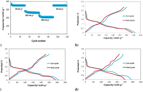
Figure 5. a) The rate capacity of MoS2+5% weight SiO2. Discharge-charge profiles of selected cycles
at current density 50 mA g-1 of: b) MoS2+5% weight TiO2|1M LiPF6 in EC/DMC|Li; c)
MoS2+10% weight TiO2|1M LiPF6 in EC/DMC|Li; b) MoS2+20% weight TiO2|1M LiPF6 in
EC/DMC|Li.
It should be remembered that studying the kinetics of lithium ion transport is important in determining the performance of such a material. It also has a bearing on the number of charge/ discharge cycles. It is also worth noting that in the majority of synthesized materials based on MoS2
and TiO2, molybdenum sulphide has direct contact with the electrolyte - its coating creates liquid/ solid
phase boundaries [32-41].
Figure 5a shows the dependence of capacity on the number of cycles at variable current density. The chart shows that as the number of cycles increases with the current regime, the capacity drops. Its highest value, after the first cycle, at a current density of 5 mA g-1, is about 380 mAh g-1. The lowest, about 200 mAh g-1, was obtained after the twentieth cycle of work. MoS2 + 5% by weight
TiO2 behaves in a rather typical way - increasing the current density causes a decrease in capacity,
with the difference that in the case of commercially used materials, this decrease is extended over time. It can be noticed in Figure 5b that the capacity obtained after the first life cycle of the cell is lower than in the case of an electrode paste without an additive. The value was approximately 360 mAh g-1. In the second cycle, in the insertion process, the capacity is estimated at approximately 345 mAh g-1, which gives a reversibility of approximately 96%. Within one cycle the capacity value is not
the same. This indicates the fact that the electrode is incompletely reversible with such a paste during a duty cycle of about 78% (for the first cycle: insertion - 360 mAh g-1, deindersation - 280 mAh g-1).
capacity after the first insertion process (310 mAh g-1) compared to the reference electrodes and doped at 5% by weight.
The capacity after the second charge is at 300 mAh g-1, which gives a 97% reversibility. This indicates an improvement of this parameter in comparison with the previous variants. For the first cycle, for the deindication process, a capacity of about 255 mAh g-1 is obtained. Thanks to this, the reversibility, within one cycle, is 82%.
[image:9.596.153.448.294.451.2]From Figure 5d it follows that 20% by weight addition of titanium oxide (IV) led to an even greater reduction in capacity after the first lithium ion insertion compared to smaller additions (first cycle: 295 mAh g-1, second cycle: 250 mAh g-1). This gives a reversibility of around 85%. This value is also the lowest when it is combined with other electrodes modified with titanium (IV) oxide. Within one cycle the capacity changes (for the first cycle): insertion - 295 mAh g-1, deindustrialization - 225 mAh g-1, which gives a reversibility of 76%. This is the lowest of three (for three different electrodes).
Figure 6. CV curves of the MoS2+ 5, 10, 20% weight TiO2| 1M LiPF6 in EC/DMC|Li. Scan rate: 0.2
mV·s-1, first scan.
In the case of the voltamperogram for TiO2 modified electrodes (Fig. 6), only the curves for 10
and 20% by weight can be discussed. supplement. Both illustrate the behavior of the electrodes after the first cycle of work. Cathodic peaks at a potential of about 1 V correspond to the reaction of insertion of Li+ ions, during which the MoS2 structure changes from rhombohedral to octahedral. For
cathodic peaks located in the vicinity of 1 V and 2.25 V, no equivalents were found in the publications that were the basis for the interpretation of the charts. Anode peaks occur around potentials of about 1.9 V and 2.1 V. They are assigned, probably the next, reactions: oxidation of Mo to MoS2 and Li+ to
LixTiO2.
When using multilayer nanospheres formed from alternating layers of MoS2 and carbon as the
the surface of graphene (G) vertically, inter-phase interaction between C-O-Mo bonds can increase the electron transfer rate and the structural stability of the MoS2/G electrode, which is very beneficial for
[image:10.596.68.527.239.717.2]Improving the performance and life cycle of the cell. Graphene layers contribute to improved composite electronic conductivity. At the same time they act not only as a material through which homogeneous dispersion of molybdenum sulphide nanoparticles (IV) is possible, but also as a buffer. It facilitates the reduction of the change in volume of electrode material generated during the life cycle of the cell [4].
Table 3. Capacitance values of MoS2 electrodes without additives
Current C / A kg-1
Capacities / Ah kg-1
Material Electrode Ref
0.1 C
700 3700 MoS2/C multilayer nanospheres cathode [3]
670
910 MoS2 nanobowls
anode [2]
642 MoS2@C-400 nanobowls
988 MoS2@C-500 nanobowls
1024 MoS2@C-600 nanobowls
0.2 C
850 MoS2 nanobowls
546 MoS2@C-400 nanobowls
892 MoS2@C-500 nanobowls
958 MoS2@C-600 nanobowls
0.3 C 700 1390
MoS2/C multilayer nanospheres
cathode [3]
0.5 C
790
670
660 MoS2 nanobowls
anode [2]
344 MoS2@C-400 nanobowls
737 MoS2@C-500 nanobowls
792 MoS2@C-600 nanobowls
1 C
537 MoS2 nanobowls
221 MoS2@C-400 nanobowls
679 MoS2@C-500 nanobowls
657 MoS2@C-600 nanobowls
2 C
270 MoS2 nanobowls
141 MoS2@C-400 nanobowls
482 MoS2@C-500 nanobowls
504 MoS2@C-600 nanobowls
5 C
99 MoS2 nanobowls
69 MoS2@C-400 nanobowls
353 MoS2@C-500 nanobowls
363 MoS2@C-600 nanobowls
10 C
5 MoS2 nanobowls
67 MoS2@C-400 nanobowls
185 MoS2@C-500 nanobowls
171 MoS2@C-600 nanobowls
100 A kg-1
-
1077
MoS2 multilayer graphene nanospheres [4]
1000 A kg-1
907
14 MoS2
[5] 192 MoS2/graphene (1:1) - composite aerogels
348 MoS2/grafen (0.5:1) - composite aerogels
250 MoS2/graphene (0.25:1) - composite aerogels
TiO2 is an amphoteric oxide. It reacts with concentrated sulfuric acid (VI) to give titanyl
It is also characterized by high mechanical resistance and photochemical stability [6]. When dealing with core-shell composites formed with TiO2 together with the MoS2 nanolayers by hydrothermal
method, where one of the substrates is cetyltrimethylammonium bromide, they have better electrochemical properties than pure molybdenum (IV) sulphide. Then we have to deal with a higher specific capacity and reversibility during the cyclic operation of the cell. This may result from the dispersion of sulphide nanowires on the surface of the oxide, which accelerates surface electrode reactions and ensures structural stability. In addition, the TiO2 nanospheres themselves act as
stabilizers of the MoS2 structure after many cycles of the system [7].
In the case of using the synthesized TiO2@MoS2/C system as the electrode paste, an
improvement in the electrochemical properties is also obtained as compared to the unmodified molybdenum (IV) sulphide. This is due to the fact that the presence of oxide plates improves cycle speed and efficiency. Thanks to the scaffolding in the form of titanium oxide (IV), MoS2/C, it has the
ability to attach to it, which prevents the phenomenon of exfoliation of molybdenum sulphide (IV) from becoming quite common [8].
[image:11.596.69.526.391.528.2]Table 4 presents literature data describing the value of the specific capacitance of the electrode depending on the material used in the preparation of the electrode paste
Table 4. Capacity for electrodes with TiO2
Current / A·kg-1
Capacity / Ah·kg-1
Material Ref
100
643 TiO2@MoS2/C spheres [8]
467 TiO2@MoS2 TiO2 -nanospheres, MoS2-
nanospheres
[7]
750 C@MoS2 [9]
400 MoS2 supported on carbon nanotubes [10]
947 3D flower-like MoS2 spheres [11]
982 MoS2/C nanospheres - in foam-like carbon sheets [12]
3.3. The electrode based on MoS2/SiO2
The graph below (Figure 7a) shows the capacitance values in relation to the number of cycles performed, using different current regimes, for MoS2 doped with 5% by weight. SiO2. As you can see,
the system performed 20 cycles with an initial capacity of 310 mAh g-1, which gradually decreased
0 100 200 300 400
0 20 40 60 80 100 120
C a p a c it y / m A h g -1 Cycle number 50 mA g-1
200 mA g-1
500 mA g-1
50 mA g-1
0 0.5 1 1.5 2 2.5 3 3.5
0 50 100 150 200 250 300 350 400
P o te n ti a l / V
Capacity / mAh g-1
1st cycle 2nd cycle
a) b)
0 0.5 1 1.5 2 2.5 3 3.5
0 50 100 150 200 250 300 350
P o te n ti a l / V
Capacity / mAh g-1
1st cycle 2nd cycle
[image:12.596.53.515.68.373.2]c) d)
Figure 7. a) The rate capacity of MoS2+5% weight SiO2. Discharge-charge profiles of selected cycles
at current density 50 mA g-1 of: b) MoS2+5% weight SiO2|1M LiPF6 in EC/DMC|Li; c)
MoS2+10% weight SiO2|1M LiPF6 in EC/DMC|Li; b) MoS2+20% weight SiO2|1M LiPF6 in
EC/DMC|Li.
Figure 7b shows the constant-charge charge / discharge curves for an anode containing 5% by weight. SiO2 for the first two cycles. For the first lithium ion insertion into the anode structure
(charging curve), the cell's capacity is approximately 380 mAh g-1. On the second charge this capacity is reduced by about 10% and is 340 mAh g-1.
The curves shown in Figure 7c were created by examining a cell with an anode containing 10% by weight. SiO2. In this case the 1 cycle capacity is lower than for a 5 wt% system. SiO2 i is
approximately 325 mAh g-1. With the second lithium ion insertion, it decreases only by 0.6% and is 310 mAh g-1.
For a cell with an anode containing 20% by weight SiO2 (Fig. 7d) the capacity achieved during
loading/unloading is the lowest of those presented so far. For charging during the first cycle, the capacity is approximately 280 mAh g-1, and for the second 270 mAh g-1. This difference is negligible. In studies of new electrode materials that are synthesized, attainable properties are determined by the type of additive.
For example, the very thin MoS2/chitosan-assisted graphs produced after the first lithium ion
insertion have a capacity of 988 mAh g-1 (charging) and 1432 mAh g-1 (discharge) - reversibility 69% [42]. Another example is the hybrid MoS2/polyaniline composite (MoS2/PANI), the capacity of which
material MoS2/rGO, which is synthesized in the presence of SiO2 capacity of the charging process
1260.5 mAh g-1, and discharging 2279 mAh g-1 [43].
In addition, environmentally friendly and low cost carbon nanostructures MoS2/carbon fibers
(MoS2/SFTC) have been prepared by an easy hydrothermal method. They showed the reversible
specific capacity of 437.2 mAh g-1 is supported after 50 cycles at a current density of 50 mA g-1 (even at high current density of 2000 mA g-1, the reversible specific capacity could be supported at 241.1 mAh g-1)[44].
The efficient use of titanium dioxide in photoelectrochemistry is limited by the high value of the forbidden gap of TiO2 (Eg = 3.0-3.4 eV). Heterocomponents consisting of semiconductors
significantly differing in the electronic structure allow for extending the range of light absorption and increasing the recombination time. The formation of TiO2-based composites-based materials enjoys
growing interest. rGO, the oxidised form of graphene, appears to be an interesting material for forming bonds with semiconductors and metals, and the layered MoS2 has an electronic structure that allows its
use as a component of the photo-water decomposition in the PEC (PhotoElectrochemical Cell). The aim of the work was to examine the effect of the addition of rGO and MoS2, deposited under various
conditions on the properties of TiO2-based photoanodes. In the presented work, rGO was synthesized
by the modified Hummers method and MoS2 by the hydrothermal method, then deposited on the
surface of TiO2 (nanotubes or continuous layer) electrochemically (rGO, MoS2) and hydrothermal
[image:13.596.133.445.431.607.2](MoS2).
Figure 8. CV curves of the MoS2+ 5, 10, 20% weight SiO2| 1M LiPF6 in EC/DMC|Li. Scan rate: 0.2
mV·s-1, first scan.
In summary we can thought that on basis of above analyses and evidences, the MoS2/TiO2 or
SiO2 shows significantly enhanced cycling stability and rate capability compared with pure MoS2,
which can be attributed to their favorable structural advantages (Fig. 9): the abundant mesopores and defect-rich, interlayer-expanded, and few-layered MoS2 facilitate the Li-ion diffusion across the
[image:14.596.120.477.177.402.2]electrode and active material, respectively [45].
Figure 9. Schema of MoS2/SiO2 or TiO2 anode material during the charge/discharge processes.
Moreover the continuous porous structure can provide sufficient void space to buffer the mechanical stress arising from the volume variation upon Li-ion insertion/deinsertion, resulting in a robust architecture.
Table 5. Comparison of mean capacitance values for galvanostatic charging/discharging and reversibility during cyclic operation of the electrodes tested.
Materials Capacity / mAh g
-1
Reversibility / % Charge Discharge
MoS2 368 210 57
MoS2+5%(wt./wt.)TiO2 353 270 77
MoS2+10%(wt./wt.)TiO2 305 250 82
MoS2+20%(wt./wt.)TiO2 273 240 88
MoS2+5%(wt./wt.)SiO2 360 300 83
MoS2+10%(wt./wt.)SiO2 318 280 88
MoS2+20%(wt./wt.)SiO2 275 245 89
[image:14.596.117.480.567.715.2]
values are obtained, which is a signal that further research on MoS2 in different systems can produce
satisfactory results.
4. CONCLUSIONS
Molybdenum disulphide has been widely used in many branches of industry due to its properties. It is used as various types of coating, increasing resistance to load, friction and corrosion. It has been successfully used for the production of catalysts involved in the processes: HDS, HER and the synthesis of mixed alcohols. It also has properties thanks to which it can become an important material in the broadly understood field of optoelectronics electronics, or as an electrode material.
Experimental studies have shown that MoS2 nanoparticles have catalytic properties that can be
used in the electrocatalytic production of hydrogen. The activity of molybdenum disulfide nanoparticles can be increased by doping with cobalt. Numerous research works indicated that the formed hybrids of MoS2, tungsten monocarbide and graphene oxide were characterized by large
surface area, increased conductivity and excellent catalytic activity in the HER reaction.
The aim of the study was to investigate molybdenum sulphide as a potential electrolyte material used in lithium-ion cells and to improve its electrochemical properties. The most commonly used anode was graphite. MoS2 has a higher capacity than graphite (~372 mAh
g-1) by about 180%. The problem, however, is its short life span (up to 20 work cycles). The
voltammogram for the reference electrodes, on which it can be clearly seen that with each successive work cycle there is a flattening of the peaks. This demonstrates the fact that the electrode material has been depleted. Additives were used to improve electrochemical properties of molybdenum sulphide (IV).
Analysis of comparative electrodes (MoS2 without additives) was started from the
electrochemical studies of impedance spectroscopy. As a result, they learned their resistance before the first and subsequent work cycles. Values have decreased. This is due to the formation of the passive layer of the SEI (Solid Electrolyte Interphase) on the surface of the electrode. The mechanism of their reduction is that after the formation of the lithium ion, the reaction of "embedding" lithium ions is favored because the surface of the electrode is isolated from the electrolyte by a layer of insoluble compounds, eg. lithium alkyl carbonate (CH2OCO2Li)2, which is the decomposition product EC.
Taking into account the electrode capacitance at the galvanostatic storage, the best results were achieved using pure molybdenum sulphide. No add-on did not increase the capacity. Within one additive, as it increased its mass share, capacity decreased. With galvanostatic discharge, the highest capacity was obtained for an anode with 5 wt% SiO2. By comparing the corresponding electrodes with
The results indicate that the structure provides active sites for the storage of lithium ions, facilitates fast transport of lithium ions and electrons. The aggregation of MoS2 particles during
lithiation/delithiation processes, is leded to the high specific capacity and rate capability.
ACKNOWLEDGEMENTS
Support of grant 03/31/DSPB/0335 is gratefully acknowledged.
References
1. B. Peng, J. Chen, Coordination Chemistry Reviews, 253 (2009) 2805.
2. C. Cui, X. Li, Z. Hu, J. Xu, H. Liu, J. Ma, Royal Society of Chemistry, 5 (2015) 92506.
3. O.L. Shyyko, O.V. Kotsyubynsky, M.I. Budzulyak, P. Sagan, Nanoscale Research Letters, 11-243 (2016) 1.
4. Y. Teng, H. Zhao, Z. Zhang, Z. Li, Q. Xia, Y. Zhang, L. Zhao, X. Du, Z. Du, P. Lv, K. Świerczek American Chemical Society Nano, 10 (2016) 8526.
5. T. Zhang, l. Kong, M. Liu, Y. Dai, K. Yan, B. Hu, Materials nad Design,112 (2018) 86. 6. J. Cho, C.S. Kim, S.I. Yoo, Electrochemical Solid-State Letters, 3 (2000) 362.
7. B. Zhao, Z. Wang, Y. Gao, L. Chen, M. Lu, Z. Jiao, Y. Jiang, Y. Ding, L. Cheng, Applied of Surface Science, 390 (2016) 209.
8. G. Li, L. Yu, H. Hu, Q. Zhu, Y. Wang, Y. Yu, Electrochimica Acta, 212 (2016) 59. 9. L. Zhang, X.W. Lou, Chemistry European Journal, 20 (2014) 5219.
10.Q. Wang, J.H. Li, The Journal of Physichal Chemistry, C 111 (2007) 1675.
11.T. Yang, Y.J. Chen, B.H. Qu, L. Mei, D. Lei, H.N. Zhang, Q.H. Li, T.H. Wang, Electrochimica Acta, 115 (2014) 165.
12.B.B. Wang, Y. Xia, G. Wang, Y.X. Zhou, H. Wang, Chemistry European Journal, 309 (2017) 417. 13.K.-X. Wang, X.-H. Li, J.-S. Chen, Advance of Materials, 27 (2015) 527.
14.Shu H, Li F, Hu C, Liang P, Cao D, X. Chen, Nanoscale, 8 (2016) 2918-2926.
15.Z. Zeng, X. Zhang, K. Bustillo, K. Niu, C. Gammer, J. Xu, H. Zheng, Nano Letters, 15 (2015) 5214.
16.B. Kurc, International Journal of Electrochemistry Science, 13 (6) (2018) 5938. 17.B. Kurc Journal Solid State of the Electrochemistry, 16 (2014) 673.
18.R. Tenne, L. Margulis, M. Genut, G. Hodes, Nature, 360 (1992) 444.
19.H.S.S. Ramakrishna Matte, A. Gomathi, A.K. Manna, D.J. Late, R. Datta, S.K Pati, C.N.R. Rao Angewandte Chemie International Edition, 49 (2010) 4059.
20.R.R. Haering, J.A.R. Stiles, K. Brandt, US Patent, 1980, No. 4224390. 21.X. Chen, Z. Chen, J. Li, Chinese Science Bulletin, 58 (2013) 1632.
22.F. Xiong, H. Wang, X. Liu, J. Sun, M. Brongersma, E. Pop, Y. Cui, Nano Letters, 15 (2015) 6777. 23.G. Guo, J. Hong, C. Cong, X. Zhou, Journal of Materials Science, 40 (2005) 2557.
24.J. Zhao, H. Ren, C. Gu, W. Guan, X. Song, Journal Alloys of Compounds, 781 (2019) 174. 25.Z.Y. Zhang, S.L. Wu, J.Y. Cheng, W.J. Zhang, Energy Storage Materials, 15 (2018) 65.
26.X.H. Tian, Q.M. Gao, H. Zhang, Z.Y. Li, H. Xiao, Q. Zhang, L. Ma, Nanoscale, 10 (2018) 5222. 27.Y.C. Jiao, A.M. Hafez, D.X. Cao, A. Mukhopadhyay, Y. Ma, H.L. Zhu, Small, 14 (2018) 1. 28.L. Vieira, J.R.M. Neto, O.P. Ferreira, R.M. Torresi, S.I.C. Torresi, O.L. Alves, RSC Advances, 8
(2018) 30346.
29.X.D. Zheng, Y.L. Zhu, Y.L. Sun, Q.J. Jiao, J. Power Sources 395 (2018) 318.
31.Y.C. Jiao, A. Mukhopadhyay, Y. Ma, L. Yang, A.M. Hafez, H.L. Zhu, Advances of Energy Materials, 8 (2018) 1.
32.M. Mao, L. Mei, D. Guo, L. Wu, D. Zhang, Q. Li, T. Wang, Nanoscale, 6 (2014) 12350. 33.B. Guo, K. Yu, H. Fu, Q. Hua, R. Qi, H. Li, H. Song, S. Guo, Z. Zhu, Journal of Materials
Chemistry A, 3 (2015) 6392.
34.J.-Y Liao, B.D. Luna, A. Manthiram, Journal of Materials Chemistry A, 4 (2014) 801-806.
35.R. Dai, A. Zhang, Z. Pan, A.M. Al-Enizi, A.A. Elzatahry, L. Hu, G. Zheng, Small, 12 (2016) 2792. 36.W. Xu, T. Wang, Y. Yu, S. Wang, Journal of Alloys Compounds, 689 (2016) 460.
37.G. Li, L. Yu, H. Hu, Q. Zhu, Y. Wang, Y. Yu, Electrochimica Acta, 212 (2016) 59. 38.X. Xu, Z. Fan, S. Ding, D. Yu, Y. Du, Nanoscale, 6 (2014) 5245.
39.X. Li, W. Li, M. Li, P. Cui, D. Chen, T. Gengenbach, L. Chu, H. Liu, G. Song, Journal of Materials Chemistry A, 3 (2015) 2762.
40.B. Chen, N. Zhao, L. Guo, F. He, C. Shi, C. He, J. Li, E. Liu, Nanoscale, 7 (2015) 12895. 41.B. Chen, E. Liu, F. He, C. Shi, C. He, J. Li, N. Zhao, Nano Energy, 26 (2016) 541.
42.M. Lin, Z. Xiaoping, X. Limei, X. Xuyao, Z. Lingling, C. Weixiang, Electrochimica Acta 167 (2015) 39.
43.Y. Lin, T. Su, Appied Surface Science, 387 (2016) 661.
44.Y. Liu, A. Qin, S. Chen, L. Liao, K. Zhang, Z. Mo, International Journal of Electrochemistry Science,.13 (2018) 2054.
45.B. Chen, H. Lu, N. Zhao, C. Shi, E. Liu, C He, L Ma, Journal of Power Sorces 387 (2018) 16.