Research Article
On the Implementation of a Dynamic Direction Modulation
System with Vector Modulators
Edith Annette Cabrera-Hernández
,
1Josep Parron,
1and Alan Tennant
21Department of Telecommunication and System Engineering, Escola d’Enginyeria, Universitat Autònoma de Barcelona (UAB),
Campus de la UAB, Q Building, Carrer de les Sitges, Bellaterra, Cerdanyola del Vallès, 08193 Barcelona, Spain
2Department of Electronic & Electrical Engineering, Portobello Centre, The University of Sheffield, Pitt Street, Sheffield (S1 4ET), UK
Correspondence should be addressed to Edith Annette Cabrera-Hernández; edithannette.cabrera@uab.cat
Received 26 November 2018; Revised 18 February 2019; Accepted 20 February 2019; Published 2 May 2019
Academic Editor: Shiwen Yang
Copyright © 2019 Edith Annette Cabrera-Hernández et al. This is an open access article distributed under the Creative Commons Attribution License, which permits unrestricted use, distribution, and reproduction in any medium, provided the original work is properly cited.
Dynamic directional modulation (DDM) has already proven to be an efficient technique to achieve physical layer security in wireless communications. System architectures based on vector modulators provide aflexible framework to implement synthesis methods that allow us to obtain increased security and/or independent multichannel transmissions. However, the implementation of DDM with vector modulators requires an accurate calibration (amplitude and phase) of every component in the RF path. In this contribution, we study the sensitivity of the response of a DDM system based on commercial vector modulators showing how to correct the nonideal behavior of all the components thanks to theflexibility provided by the vector modulator.
1. Introduction
Over the past few decades, wireless communication systems have expanded at an exponential rate, fueled by consumer demand and aided by increasing levels of technological advancement in terms of scalability, flexibility, and low reduced cost. However, wireless systems are more susceptible to interception than their wired counterparts due, partially, to the absence of physical boundaries in the transmission medium. An attractive solution to improve the security of wireless transmission is to apply encryption at the physical layer level to limit the amount of information that an illegit-imate receiver can extract from the transmission medium [1]. The use of phased arrays to project nulls in the directions of illegitimate receivers [2] can be considered an antecedent to current physical layer security techniques. This method is simple and efficient but is limited by the need to know in advance the locations of illegitimate eavesdroppers that will tend to obfuscate their position.
Phased arrays can be also used to generate directional modulation (DM) [3–13]. This is an attractive option to achieve physical layer security since it is only necessary to
know the direction of the legitimate receiver. A DM transmit-ter projects digitally modulated information signals into a prespecified secure spatial direction in free space, while simultaneously the constellation formats of the same sig-nals are distorted in all other directions [3]. In the case that the distortion is dynamically updated (usually at the symbol rate) the DM is referred as dynamic (DDM) and provides better performance in terms of security than static DM (SDM) [4].
The hardware architectures of a DDM system with phased arrays mainly differ in the array feeding network implementation and we can distinguish: Fourier beam-forming lens [5], radio frequency (RF) switch arrays [6–8], reconfigurable attenuators and/or phase shifters [9–11], and vector modulators [3, 12, 13]. In this work, we will consider the option of vector modulators (Figure 1) since it is very
flexible and allows us to easily implement DM synthesis methods [3] to obtain increased security and/or independent multichannel transmissions [12, 13].
The performance of a DDM system is usually assessed in terms of the bit error rate (BER) increase of the received sig-nal in other directions than the prespecified secure direction Volume 2019, Article ID 9784252, 13 pages
[3–10] without considering how sensitive this BER is to small variations in the response of the components used. However, the implementation of DDM with vector modulators requires an accurate calibration (amplitude and phase) of every component in the RF path; otherwise, the transmitted constellations in the secure direction could be distorted as it was shown in a preliminary study in [14].
This contribution is aimed at studying the sensitivity of the response of a DDM system based on commercial vector modulators and showing how to correct the nonideal behav-ior of its components thanks to theflexibility provided by the vector modulator. The paper is organized as follows. Section 2 describes the system architecture and some concepts related to the generation of DDM. Section 3 derives the theoretical expressions for the S21 parameter of the vector modulators for transmitting DDM considering real RF com-ponents. Section 4 evaluates the quality of the transmitted signal in the secure direction when commercial RF compo-nents are used and discusses the trade-off between power and security. Finally, the main conclusions of the work are summarized in Section 5.
2. DDM System Description
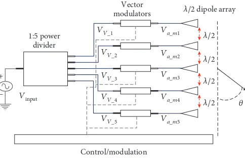
Figure 1 shows the scheme of the DDM transmission system under consideration. It is composed of a 5-way power divider, followed by 5 vector modulators (VM) that feed an
array of 5 half wavelength long dipole antennas in a side by side arrangement; the spacing between dipoles is λ/2 (λ is the free space wavelength). The operating frequency of the RF source of the system is set arbitrarily to 2.45 GHz. A full model of the system has been created using the electromag-netic simulation software FEKO [15].
The array radiation pattern used to transmit symbolmin a given directionθcan be expressed as
Sm θ = 〠 5
n=1Bmn· AEPn θ , 1
where AEPn (θ) is the active element pattern of antenna n [16] andBmn is the weight ofAEPn (θ) when transmitting symbol m. By varying the control inputs of the vector Control/modulation
1:5 power divider
Vector
modulators 𝜆/2 dipole array
+
− Vinput
VV_2
VV_3
VV_4
VV_5
VV_1 Va_m1
Va_m2
Va_m3
Va_m4
Va_m5
𝜆/2
𝜆/2
𝜆/2
𝜆/2 𝜃
Figure1: Transmission system demonstrator block diagram.
V− a_1n
Z0 Z0 Z0
V0
Z0 Z0
V−
a_2n V−a_3n V±a_nn V−a_Nn
+
−
Figure2: Geometry for obtaining the active element pattern of the elementnof the array ofNantennas.
Z11_n Z22_n
Z21v_mn·Iv_n
Iv_n −Ia_mn
Vv_n Va_mn
− − −
+ +
+
Figure 3: Equivalent circuit for Z parameters of the vector
[image:2.600.179.421.74.230.2] [image:2.600.166.436.268.394.2] [image:2.600.317.541.433.498.2]modulators, the parameterS21of each vector modulator can be adjusted to set the desiredBmn, thus allowing for tailored radiation patterns. As such, equation (1) is familiar as a clas-sic form describing the array radiation pattern.
The required weights for a DM system (Bmn_DM) can
be obtained using the orthogonal vector approach described in [3]: first, we design the weights for a non-DM (conventional) array (Bmn_nonDM), and next, we add
orthogonal noise (Wmn) to the former weights
(BmnDM=BmnnonDM+Wmn) in such a way as the
constella-tion at the desired secure direcconstella-tion remains invariant. When Wmn are dynamically updated (usually at the symbol rate),
we are using DDM.
The directional modulation power efficiency (PEDM) is
defined as the ratio of the power used in the non-DM array to the power used in the DM array [3]. It describes the extra power (Wmn) injected into the array to obtain the directional modulation. In Section 4, it will be shown that decreasing PEDMincreases the distortion in nondesired
directions, thus improving the privacy of the communica-tion. Therefore, there exists a compromise between security and PEDM.
3. Generation of the Radiation Patterns with the
Vector Modulators
This section is devoted to derive the expressions for theS21 parameters of the vector modulators that will allow us to generate DDM with the scheme of Figure 1.
According to [16],AEPn θ can be obtained by feeding elementnof the array with all the other array elements termi-nated in matched loadsZ0, as shown in Figure 2.
With this scheme, the matrix that contains the input voltage of antennapwhen antennanis fed with a source of 1 V can be written as
Va pn =12 U + Sa , 2
where [Sa] is theSparameter matrix of the array and [U] is the identity matrix of orderN.
With the AEP of each antenna, we obtain the weights Bmn_DMby applying the procedure described in the
previ-ous section. Then, by using the superposition principle, the matrix that contains the input voltage in antenna n when transmitting symbol mis
Va mn = 12 U + Sa · Bmn DM, 3
and the matrix that contains the input current in antenna n when transmitting symbol mbecomes
Ia mn =21Z 0
U − Sa · BmnDM 4
By combining (3) and (4), we can easily obtain the input impedance (ZL mn) and the corresponding reflection coefficient (ΓL mn). It must be noted that, even when each Vector_modulator_s21_m2 Vector_modulator_s21_m1 Dipole 2 Dipole 3 Dipole 4 Power_divider 1 2 1 2 1 2 1 2 1 2 1 2 3 4 5 6 Dipole 5 Vector_modulator_s21_m3 Vector_modulator_s21_m4 Vector_modulator_s21_m5 Vv_1
Va_m1 S21_m1
S21_m2
S21_m3
S21_m4
S21_m5
Va_m2
Va_m3
Va_m4
Va_m5 Vv_2
Vv_3
Vv_4 Vinput
Vv_5 N N N N N N Dipole 1
antenna is designed to be well matched (with all the other elements terminated in matched loads), ΓL mn changes with the element and transmitted symbol due to mutual coupling between the antennas.
It is also noted that for each element and symbol we also have
BmnDM−Va mn=Z0Ia mn 5
Hence, it can be easily derived that
Bmn DM
Va mn = 2
1 +ΓL mn 6
Our goal now becomes setting the S21 parameter for each vector modulator nand symbol m(S21 mn) that gen-erates the desired Va mn and Ia mn at the antenna input. We are going to operate under the (realistic) assumptions
40 50 60 70 80 90 100 110 120 130 140
0.2 0.3 0.4 0.5 0.6 0.7 0.8
Magnitude (V)
AEP1 AEP2 AEP3
AEP4 AEP5
X: 70
Y: 0.5167
X: 110
Y: 0.5167
X: 60
Y: 0.4176 XY: 0.4176: 120
𝜃
(a)
40 50 60 70 80 90 100 110 120 130 140
−150
−100
−50 0 50 100 150
Phase (deg)
X: 70
Y: 15.02
X: 60 Y: −100
X: 120
Y:−100
X: 110
Y: 15.02
𝜃
AEP1 AEP2 AEP3
AEP4
AEP5
(b)
that the vector modulator is a unilateral network (S12= 0), and S11 and S22 do no not change with the symbol to transmit.
The equivalent circuit for Z parameters of the vector modulator is depicted in Figure 3. The Z parameters are related to theSparameters through the following equations that assumeS12= 0[17]:
Zii n=Z0
1 +Sii n
1−Sii n , i= 1, 2, 7
Z21 mn= 2Z0
S21 mn
1−S11 n 1−S22n 8
From Figure 3, it is straight forward that
Va mn−Z21 mn·Iv n=−Z22n·Ia mn 9
by substituting (7) and (8) into (9), and after a few mathe-matical manipulations, we obtain
0 20 40 60 80 100 120 140 160 180
0 0.5 1 1.5 2 2.5 3
Magnitude (V)
PEDM = 12%
𝜃
(a)
0 20 40 60 80 100 120 140 160 180
0 0.5 1 1.5 2 2.5 3
Magnitude (V)
PEDM = 50%
𝜃
(b)
Figure6: Magnitude of radiation patterns that transmit the same symbol at 60°for two different values of PE
DM(ideal power divider and
S21 mn= 1−1 +S22ΓnΓL mn
L mn 1 +S11n
Va mn
Vv n , 10
where Vv n is the input voltage for each vector modulator (whichdoes notdepend on the transmitted symbol). Finally, recalling (6), we obtain
S21 mn= 1−S222nΓL mn 1 +S11n BmnV DM
v n 11
And for perfectly matched vector modulators (Sii n= 0,
i= 1, 2), (11) becomes
S21mn=B2mnVDM
v n 12
4. Performance Assessment of a DDM
System with Real Components
Figure 4 shows the FEKO model of the DDM system based on vector modulators of Figure 1. The dipole array is evalu-ated through full electromagnetic simulation to include mutual coupling effects between antennas. Each component of the array feeding network is characterized by its respective
40 45 50 55 60 65 70 75 80
0 0.2 0.4 0.6 0.8 1 1.2 1.4 1.6 1.8 2
Magnitude (V)
𝜃
PEDM = 50%
(a)
40 45 50 55 60 65 70 75 80
0 0.2 0.4 0.6 0.8 1 1.2 1.4 1.6 1.8 2
Magnitude (V)
𝜃
PEDM= 50%
(b)
Figure7: Magnitude of radiation patterns that transmit a 16-QAM constellation at 60°(
PEDM= 50%) using (12) to computeS21mnin the
[image:6.600.138.461.75.559.2]S parameters. Then, once we computeS21mn, using either (11) or (12), we can obtain the radiation patterns for transmitting every symbol with very low computational requirements. In thefirst approach, we are not going to con-sider the transmission lines that connect the main compo-nents of our system (power divider, vector modulators, and
antenna array) since their effects can be easily embedded inside the components.
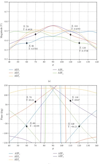
In a previous step, the AEP of each dipole has been evaluated (Figure 5) and used to obtain the array weights Bmn that will generate the desired radiation patterns for
each symbol m.
−1 −0.5 0 0.5 1
−1
−0.8
−0.6
−0.4
−0.2 0 0.2 0.4 0.6 0.8 1
PEDM = 50%, 𝜃 = 60°, SNR = 25.7 dB
(a)
−1 −0.5 0 0.5 1
−1
−0.8
−0.6
−0.4
−0.2 0 0.2 0.4 0.6 0.8 1
PEDM = 12%, 𝜃 = 60°, SNR = 17.2 dB
(b)
Figure8: DDM 16-QAM modulation transmitted at the secure direction 60°using real components and (12) to computeS
21mnin the vector
As a starting point, we use (12) to evaluate S21 mn. We assume
(1) Ideal power divider: all ports perfectly matched, balanced power division (amplitude and phase), and isolated output ports
[image:8.600.176.425.65.614.2](2) Ideal vector modulators: both ports perfectly matched andS12= 0
Figure 6 shows simulated radiation patterns that can be used to transmit the same symbol in the secure direction of 60° for two different values of PEDM. In the case of ideal
−1 −0.5 0 0.5 1
−1 −0.8 −0.6 −0.4 −0.2 0 0.2 0.4 0.6 0.8 1
PEDM = 50%, 𝜃= 60º, SNR = 310.3 dB
(a)
−1 −0.5 0 0.5 1
−1 −0.8 −0.6 −0.4 −0.2 0 0.2 0.4 0.6 0.8 1
PEDM = 12%, 𝜃= 60º, SNR = 305.8 dB
(b)
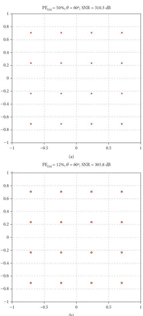
Figure9: DDM 16-QAM modulation transmitted at the secure direction 60°using real components and (11) to computeS
21mnin the vector
[image:8.600.180.423.83.347.2]components, any constellation can be (theoretically) pro-duced in a desired observation angle without issue.
In Figure 6, it is also important to highlight the trade-off between transmitted power and security: as PEDMdecreases (Wmn power increases), we have a narrower secure beam width around 60°and the distortion of symbols in undesired directions becomes larger.
Next, we introduce the characteristics of real components into the system. The power divider outputs will be assigned a nominal amplitude balance of±1.2 dB [18] and a phase var-iation of±3°. We also assume the vector modulators of [19] which show a measuredS12 parameter always below -70 dB and input and output return losses around 9 and 10 dB, respectively.
–1 –0.5 0 0.5 1
–1 –0.8 –0.6 –0.4 –0.2 0 0.2 0.4 0.6 0.8 1
PEDM = 50%, 𝜃 = 60°, SNR = 29.3 dB
(a)
–1 –0.5 0 0.5 1
–1 –0.8 – 0.6 –0.4 –0.2 0 0.2 0.4 0.6 0.8 1
PEDM = 12%, 𝜃 = 60°, SNR = 20.5 dB
(b)
Figure10: DDM 16-QAM modulation transmitted at the secure direction 60°using real components, coaxial cables and (12) to compute
Atfirst sight, one could think that, for these vector mod-ulators, the unilateral assumption is reasonably well satisfied and the input and output are fairly well matched, so the use of (12) to computeS21 mnshould be enough to generate sim-ilar radiation patterns to those that would be obtained with ideal components (Figure 7(a)). However, Figure 7(b) shows
that the radiation patterns not only have less amplitude but also are slightly distorted.
As a result, the constellation generated at the desired secure direction of 60°exhibits additional noise on the trans-mitted symbol (Figure 8). This behavior is due to thefinite output return loss of the vector modulators (S22n) and the
−1 −0.5 0 0.5 1
−1
−0.8
−0.6
−0.4
−0.2 0 0.2 0.4 0.6 0.8 1
PEDM = 50%, 𝜃 = 60°, SNR = 34.1 dB
(a)
−1 −0.5 0 0.5 1
−1
−0.8
−0.6
−0.4
−0.2 0 0.2 0.4 0.6 0.8 1
PEDM = 12%, 𝜃 = 60°, SNR = 26.1 dB
(b)
Figure11: DDM 16-QAM modulation transmitted at the secure direction 60°using real components, coaxial cables and (11) to compute
variation of the input reflection coefficient with the antenna and symbol to transmit (ΓL mn). In Figure 8, we have associ-ated a signal-to-noise ratio (SNR) to the transmitted symbols that represents the threshold of quality that can be achieved in the transmission without additional calibration. Although SNR is still quite high forPEDM= 50%, it must be noted that
the effects of real coaxial cables have not been considered here, so the case under consideration is quite favorable.
Another important result that can be derived from Figure 8 is that SNR decreases significantly with PEDM. A
low scenario PEDMwould be required in the case of a highly
secure transmission or in the case of simultaneous multi-channel transmissions to different observation angles as in [13]. Therefore, these applications demand an accurate mea-surement of the components of the system and the use of (11) to obtainS21mn.Indeed, Figure 9 shows that, in this case, we
40 50 60 70 80 90 100 110 120 130 140
0.2 0.3 0.4 0.5 0.6 0.7 0.8
Magnitude (V)
AEP1 AEP2 AEP3
AEP4 AEP5
X: 70
Y: 0.4629
X: 60
Y: 0.3705 X: 120
Y: 0.3716
X: 110
Y: 0.4593
𝜃
(a)
40 50 60 70 80 90 100 110 120 130 140
−150 −100 −50 0 50 100 150
Phase (deg)
AEP1 AEP2 AEP3
AEP4 AEP5
X: 110
Y: 69.87
X: 70
Y: 65.21
X: 60
Y: −63.99 XY: : 120−64.21
𝜃
(b)
[image:11.600.138.463.72.609.2]can transmit the desired constellations without noise regard-less of the value of PEDMused.
Finally, we add 5 commercial coaxial cables [20] in the system to connect antennas and vector modulators, which present attenuation of 1 1 dB ± 0 1 dB and phase variation of±3°, and input and output return losses (Sii) ranged from 20 to 40 dB.
Figure 10 shows the transmitted constellation for the secure direction of 60°when we use (12) to computeS21 mn, real components and coaxial cables which were not included in the AEP measurement. It is noticed that an improvement of over 3 dB in SNR with respect to Figure 8 is obtained. This result may seem counterintuitive since the addition of coaxial cables increases amplitude and phase variations. However, it makes sense if we consider thatΓL mnfor the array with coax-ial cables is not as sensitive to the symbol to be transmitted due to the additional losses. Conversely, as observed in Figure 10, we also see a reduction of 6 dB in the constellation amplitude which is significantly larger than the 1.1 dB intro-duced by coaxial cables.
Keeping the same scenario and using (11) instead of (12) to compute S21 mn, we obtain some improvements (Figure 11). Now, the constellation amplitude has only been reduced by 1 dB, as expected. Nevertheless, although SNR has improved 5-6 dB with respect to Figure 10, we still have noisy symbols. The only way to obtain the results of Figure 9 is by using the AEP of each element of the array with coaxial cables (Figure 12) in the computations. Notice in Figure 12 the additional attenuation of 1 dB and the slightly loss of symmetry with respect to Figure 5.
5. Conclusions
In this work, a FEKO model of a DDM system based on a power divider and vector modulators has been used to dem-onstrate that the system performance relies heavily on the precision with which theS21parameters of the vector modu-lators are set.
We have derived an expression for theS21 parameters that takes into account the weight to be set for each antenna and symbol (that depends on the AEP of each antenna) and nonideal effects of the components such as unbalanced RF paths (amplitude and phase) andfinite return losses.
Simulations show that, when nonideal effects are not considered in the computation of S21, different sets of weights, that should generate the same symbol in a desired observation angle, produce slightly different symbols that have the appearance of noise. For that reason, we have asso-ciated a SNR to the transmitted symbols. This SNR decreases when we decrease PEDMto improve the security of the
trans-mission in a single direction or to transmit, simultaneously, to different observation angles. Therefore, for these applica-tions, theSparameters of the components should be accu-rately measured and considered in the computation of S21. Also, we have shown that the AEP of every antenna needs to be accurately evaluated together with the coaxial cables that feed the array. Small variations in amplitude and phase in the AEPs used to obtain the weights may result in a signif-icant reduction of the amplitude of the transmitted symbols.
Data Availability
The FEKO model and data used to support the findings of this study are available from the corresponding author upon request.
Conflicts of Interest
The authors declare there is no conflict of interest regarding the publication of this article.
Acknowledgments
This work was supported by the Universitat Autònoma de Barcelona, the Spanish Ministry of Economy and Competi-tiveness, and FEDER funds through Project TEC2015-69229-R.
References
[1] A. Mukherjee, S. A. A. Fakoorian, J. Huang, and A. L. Swindlehurst, “Principles of physical layer security in mul-tiuser wireless networks: a survey,” IEEE Communications Surveys & Tutorials, vol. 16, no. 3, pp. 1550–1573, 2014. [2] S. A. Schelkunoff,“A mathematical theory of linear arrays,”
Bell System Technical Journal, vol. 22, no. 1, pp. 80–107, 1943. [3] Y. Ding and V. F. Fusco,“A vector approach for the analysis and synthesis of directional modulation transmitters,” IEEE Transactions on Antennas and Propagation, vol. 62, no. 1, pp. 361–370, 2014.
[4] Y. Ding and V. F. Fusco,“Establishing metrics for assessing the performance of directional modulation systems,” IEEE Transactions on Antennas and Propagation, vol. 62, no. 5, pp. 2745–2755, 2014.
[5] Y. Ding, Y. Zhang, and V. Fusco, “Fourier Rotman lens enabled directional modulation transmitter,” International Journal of Antennas and Propagation, vol. 2015, Article ID 285986, 13 pages, 2015.
[6] N. Valliappan, A. Lozano, and R. W. Heath,“Antenna subset modulation for secure millimeter-wave wireless communica-tion,”IEEE Transactions on Communications, vol. 61, no. 8, pp. 3231–3245, 2013.
[7] Q. Zhu, S. Yang, R. Yao, and Z. Nie,“Directional modulation based on 4-D antenna arrays,”IEEE Transactions on Antennas and Propagation, vol. 62, no. 2, pp. 621–628, 2014.
[8] C. Sun, S. Yang, Y. Chen, J. Guo, S. Qu, and J. Hu,“4-D retro-directive antenna arrays for secure communication based on improved directional modulation,” IEEE Transactions on Antennas and Propagation, vol. 66, no. 11, pp. 5926–5933, 2018.
[9] M. P. Daly and J. T. Bernhard,“Directional modulation tech-nique for phased arrays,” IEEE Transactions on Antennas and Propagation, vol. 57, no. 9, pp. 2633–2640, 2009. [10] M. P. Daly, E. L. Daly, and J. T. Bernhard,“Demonstration of
directional modulation using a phased array,”IEEE Transac-tions on Antennas and Propagation, vol. 58, no. 5, pp. 1545– 1550, 2010.
[11] H. Shi and A. Tennant,“Simultaneous multichannel spatially directive data transmission using direct antenna modulation,”
[12] Y. Ding and V. Fusco,“A review of directional modulation technology,”International Journal of Microwave and Wireless Technologies, vol. 8, no. 7, pp. 981–993, 2016.
[13] S. Mufti, A. Tennant, and J. Parrón,“Dual channel broadcast using phase-only directional modulation system,” in 2018 IEEE International Symposium on Antennas and Propagation (APS-URSI), pp. 2219-2220, Boston, MA, USA, 2018. [14] E. A. Cabrera-Hernández, J. Parrón, and A. Tennant,“Infl
u-ence of non-ideal components in a dynamic directional mod-ulation system,” in 2018 IEEE-APS Topical Conference on Antennas and Propagation in Wireless Communications (APWC), pp. 882–885, Cartagena de Indias, Colombia, 2018. [15] FEKO EM, “Simulation software,” https://altairhyperworks
.com/product/FEKO.
[16] D. M. Pozar,“The active element pattern,”IEEE Transactions on Antennas and Propagation, vol. 42, no. 8, pp. 1176–1178, 1994.
[17] D. M. Pozar,Microwave Engineering, John Wiley & Sons, 4th edition, 2011.
[18] “5-way power divider and combiner (PS5 series),”February 2019, https://mcli.com/products/power-dividers-combiners/ stripline/5-way-power-divider-and-combiner-ps5-series. [19] “HMC631 datasheet and product info analog devices,”
Febru-ary 2019, https://www.analog.com/en/products/rf-microwave/ phase-shifters-vector-modulators/vector-modulators/hmc631 .html#product-overview.
International Journal of
Aerospace
Engineering
Hindawi
www.hindawi.com Volume 2018
Robotics
Journal ofHindawi
www.hindawi.com Volume 2018
Hindawi
www.hindawi.com Volume 2018
Active and Passive Electronic Components
VLSI Design
Hindawi
www.hindawi.com Volume 2018
Hindawi
www.hindawi.com Volume 2018
Shock and Vibration
Hindawi
www.hindawi.com Volume 2018
Civil Engineering
Advances inAcoustics and VibrationAdvances in
Hindawi
www.hindawi.com Volume 2018 Hindawi
www.hindawi.com Volume 2018
Electrical and Computer Engineering
Journal of
Advances in OptoElectronics
Hindawi
www.hindawi.com Volume 2018
Hindawi Publishing Corporation
http://www.hindawi.com Volume 2013
Hindawi www.hindawi.com
The Scientific
World Journal
Volume 2018Control Science and Engineering Journal of
Hindawi
www.hindawi.com Volume 2018
Hindawi www.hindawi.com
Journal of
Engineering
Volume 2018
Sensors
Journal ofHindawi
www.hindawi.com Volume 2018
Machinery
Hindawi
www.hindawi.com Volume 2018
Modelling & Simulation in Engineering Hindawi
www.hindawi.com Volume 2018
Hindawi
www.hindawi.com Volume 2018 Chemical Engineering
International Journal of Antennas and
Propagation International Journal of
Hindawi
www.hindawi.com Volume 2018 Hindawi
www.hindawi.com Volume 2018
Navigation and Observation International Journal of
Hindawi
www.hindawi.com Volume 2018