UNIVERSITI TEKNIKAL MALAYSIA MELAKA
AUTOMATIC COOLING SYSTEM MODEL USING PELTIER
THERMOELECTRIC COOLER FOR LIGHTNING
DETECTION APPLICATION
This report is submitted in accordance with the requirement of the Universiti Teknikal Malaysia Melaka (UTeM) for the Bachelor of Electrical Engineering
Technology (Industrial Power) with Honours.
by
FAUZI BIN MOHD MAHOR
B071410191
930722-01-5935
DECLARATION
I hereby, declared this report entitled “PSM Title” is the results of my own research except as cited in references.
Signature : ……….
Author’s Name : Fauzi bin Mohd Mahor
Date : ………
APPROVAL
This report is submitted to the Faculty of Engineering Technology of UTeM as a partial fulfillment of the requirements for the degree of Bachelor of Electrical Engineering Technology (Industrial Power) with Honours. The member of the supervisory is as follow:
……… (MASLAN BIN ZAINON)
ABSTRACT
A Lightning Detection Application (LDA) is a system that uses electronic components that are highly sensitive to ambient temperature. High temperature can affect electronic components from functioning properly. Besides, the Lightning Detection System is easily heated because it receives high voltage. The conventional cooling system is impractical to protect a lightning detection application because it is not economical and not environmentally friendly. Therefore, a thermoelectric cooling Peltier is a better alternative material to protect the lightning detection application. The aim of this project is to design and build an automatic cooling system for lightning detection application using a thermoelectric Peltier module andto design a temperature monitoring system that can be displayed in a module and smartphone. Other than that, the objective is to develop a prototype as an industrial concept and as an educational training tool for academic institution and community. As expected, the thermoelectric Peltier was used as a refrigerant cooler for the lightning detector cooler box and the temperature inside the cooler box in the module was monitored using a smartphone application.
ABSTRAK
Lightning Detection Application(LDA) adalah sistem yang menggunakan komponen elektronik yang sangat sensitif terhadap suhu persekitaran. Suhu yang tinggi boleh menjejaskan dan mengakibatkan komponen elektronik daripada berfungsi dengan baik dan selamat. Selain itu, Sistem Pengesan Kilat mudah dipanaskan kerana ia menerima voltan tinggi. Sistem penyejukan konvensional adalah tidak praktikal untuk melindungi aplikasi pengesanan kilat kerana ia tidak menjimatkan dan tidak mesra alam. Oleh itu, Peltier penyejukan termoelektrik adalah bahan alternatif yang lebih baik untuk melindungi aplikasi pengesanan kilat. Tujuan projek ini adalah untuk merekabentuk dan membina sistem penyejukan automatik untuk aplikasi pengesanan kilat menggunakan modul Peltier termoelektrik dan untuk merancang sistem pemantauan suhu yang boleh dipaparkan dalam modul dan telefon pintar. Selain itu, untuk membangunkan prototaip sebagai konsep perindustrian dan sebagai alat latihan pendidikan untuk institusi akademik dan komuniti. Seperti yang dijangkakan, Peltier termoelektrik digunakan sebagai penyejuk penyejuk untuk kotak sejuk pengesan kilat dan suhu di dalam kotak sejuk di dalam modul dipantau menggunakan aplikasi telefon pintar.
DEDICATION
To my beloved parents
To my supervisor, Mr. Maslan Bin Zainon To my lecturers
And not forgetting to all dear friends.
TABLE OF CONTENTS
Abstract v
Table of Content viii
List of Tables x
List of Figures xi
CHAPTER 1: INTRODUCTION 1
1.0 Introduction 1
1.1 Background 1
1.2 Problem Statement 2
1.3 Objectives 2
1.4 Project Scope 3
1.5 Conclusion 3
CHAPTER 2: LITERATURE REVIEW 4
2.0Introduction 4
2.1Thermoelectric Peltier device 4
2.1.1 Introduction 5
2.1.2 Basic Principles of Thermoelectric Device 6 2.1.3 Parameters of a Thermoelectric Module 7
2.1.4 Cold Side Temperature 7
2.1.5 Hot side temperature 7
2.1.6 Electric Peltier Cooler 8
2.2 Related Previous Project 8
2.3 Arduino 10
2.3.1 The Arduino Mega Spec 10
2.3.2 Pin Configurations 11
2.3.3 The advantages of Arduino Mega 11
2.4Bluetooth for communication system 12
2.4.1 Introduction 12
2.4.2 Bluetooth Structure 13
2.4.3 Power class of Bluetooth 13
2.5Software 14
2.5.1 MIT App Invertor 14
CHAPTER 3: METHODOLOGY 16
3.0Introduction 16
3.1Project Methodology 17
3.2 System Structure 18
3.3 Software 20
3.4 Circuit Modelling 20
3.4.1 Circuit Development Using Proteus 20
3.4.2 Encode Temperature Sensor 21
3.5Project Design 22
3.5.1 Software Project Design Using SOLIDWORKS 23
3.5.2 Hardware design 23
CHAPTER 4: RESULTS& DISCUSSION
4.0 Introduction 24
4.1 Testing the Hardware 24
4.2 System Overview 27
4.3 Experiment Result and Discussion 27
CHAPTER 5: CONCLUSION & FUTURE WORK
5.0 Introduction 34
5.1 Summary of Project 34
5.2 Achievement of the Project Objectives 35
5.3 Limitation of Project 35
REFERENCES 24
LIST OF TABLES
2.1 Power Class of Bluetooth 14
4.1 Data Analysis of Temperature for Peltier 1 28 4.2 Data Analysis of Temperature for Peltier 2 29 4.3 Data Analysis of Temperature for Peltier 3 30 4.4 Data Analysis of Temperature for Peltier 4 31
4.5 Data Analysis of Temperature 32
LIST OF FIGURES
2.1 The Peltier Device 4
2.2 Direction of the electron and hole in thermoelectric cooler 6
2.3 A water condensation system 9
2.4 The top view of Arduino Mega 10
2.5 A Detailed Pin IC in ATMEGA 2560 11
2.6 A Bluetooth’s Architecture 13
2.7 An MIT App Inventor Software 15
3.1 A Flowchart of the overall project 17
3.2 Project System block diagram 19
3.3 Proteus 8 Professional software to design the circuit 21
3.4 Flowchart of temperature sensor 22
3.5 SOLIDWORKS 2014 software 23
3.6 Hardware Design 23
4.1 Overall Hardware Project 25
4.2 Hot Side of Peltier 25
4.3 Cold Side of Peltier 26
4.4 LCD Display 26
4.5 Time vs Temperature Different for Peltier 1 28 4.6 Time vs Temperature Different for Peltier 2 29 4.7 Time vs Temperature Different for Peltier 3 30 4.8 Time vs Temperature Different for Peltier 4 31
4.9 Time vs Temperature Different 33
4.10 Time vs Humidity Different 33
CHAPTER 1
INTRODUCTION
1.0 Introduction
This chapter will explain the background of the project, the problem statements, the objectives, and conclusions. The structure of this report will be described and a better overview of the whole project will be given as well.
1.1 Background
At the present time,in a conventional cooling system,a condenser, a compressor and a blower are used to cool the surrounding area of that system. The weakness of that system is a struggle because the CFC gas emissions can pollute the air and the system is too large to fit in a small space such as a lightning detection system. A Thermoelectric Peltier module was introduced as a material to be used in the lightning detector cooling system to overcome this problem.
Besides, in general,power consumption is one of the major issues at present. However, semiconductor is the best solution to overcome this power consumption problem. Semiconductor is a goodmethodto reduce the power consumption. A Peltier module is one of the best solutions to overcome this problem. An air-conditioner carriesabout 2000 or 3000 Watt of power and a cloth iron use a minimum of 750 Watt of power. But due to the use of this Peltier module in thesesystem, lots of power consumption is saved. It can be said,the cooler gives the temperature of air conditioner in only approximately. 200 Watt.(Pasricha, 2012)
1.2 Problem Statement
A Lightning Detection Application (LDA) is a system that uses electronic components that are highly sensitive to the ambient temperature. High temperature can affect the electronic componentsfrom functioning properly. Besides, the Lightning Detection System is quickly heats up because that system received a high voltage. Based on that problem, the system required a cooling system to save the components in theuncertain weather changes. Other than that, other cooling systems do not have a monitoring system that is able to check the temperature changes. An automatic cooling system that usesthe thermoelectric Peltier becomes important and protect the electronics components from any lightning detection problems. This project will focus on an automatic cooling system using a thermoelectric Peltier, an Arduino Mega, and an MIT Application for monitoring purpose.
1.3 Objectives
The main objectives of this project are:
a) To design and build an automatic cooling system for lightning detection using a thermoelectric Peltier module.
b) To design a temperature monitoring system that can be displayed in a module and smartphone.
c) To develop a prototype as an industrial concept and as an educational training tool for academic institution (community).
1.4 Project Scope
The project scope has been carried out to achieve the project’s objective. Basically, theobjective of this project isto design a prototype of an automatic cooling system using a thermoelectric Peltier module and controlled by an Arduino Mega. All hardware meet the requirements to control the temperature changes in the lightning detection system in the box. Then,the MIT Apps inventor software is used to monitor the temperature changesusing a Smartphone.
The prototype will be implemented in a high-rise industrial building. Other than that, this prototype can revealthe understudies ofthe MIT Apps Software as aneasier system to detect the temperature changes inside the automatic cooling system box.
1.5 Conclusion
This chapter explains the project background, objectives, problem statements and scope of the project. In addition, this chapter discusses the problems to be solved and how the project is conducted.
CHAPTER 2
LITERATURE REVIEW
2.0 Introduction
This chapter shows the review of an Automatic Cooling system using a Thermoelectric Peltier, an Arduino Mega and MIT apps inventor that are used for monitoring and controlling purposes. The main sources of the study were taken from articles, case studies, journals and websites. Each source is chosen according to the relevancy of the project scope.
2.1 Thermoelectric Peltier Device
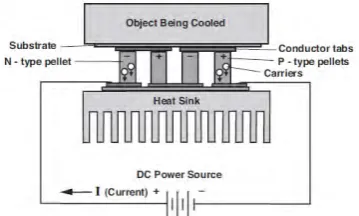
Peltier Module is one of the main components that will be used in this project. A thermoelectric (TE) cooler, also known asthe thermoelectric module or Peltier cooler, will be used in this project as a cooling system. This Peltier module has two side surfaces. When aDC source is applied to a thermoelectric cooler module, the heat will be transferred through the module from one medium to anotherin a small scale.Figure below are according to the site on the internet page is (“The Peltier Device | Zhihua Ma,” n.d.)(Specifications, n.d.)
Figure 2.1: ThePeltier Device
2.1.1 Introduction
The principle behind the thermoelectric devices was first discovered in 1821 by Thomas Seebeck. He observed that if a closed circuit was made oftwo different metals, and an electric current flowsprovidedthe junctions were maintained at different temperatures. Anopposite of this application is, froma DC voltage to a closed circuit consist ofdifferent metals causesa temperature rise at the junction of the differentmetals. (“Introduction to Thermoelectrics,” n.d.)
As a DC current passes from an N to a P material, there is a decrease in temperature at the cold junction, resulting in heat energy transferin the environment. The heat is carried through the device by an electron transport and released on the opposite (hot) side as the electrons move from a high to low energy state. The amount of heat is proportional to the current and the number of PN junctions.(“Introduction to Thermoelectrics,” n.d.)
The thermal energy flows between two sides of the module: cold and hot. Consequently, the module absorbs heat from an element touching the cold side gives it away to another element in the system (the heat sink) which is in contact with the hot side(Niculina & Svasta, 2015)
When thermoelectric coolers(TECs) are used in various applications, it is important to design a TEC for obtaining the maximum coefficient of performance of the TEC system in which the thermal resistance of heat-exchangers is given and which operates under a constant temperature difference. Several attempts have been done to analyze the performance of a TEC or a TEC system.(Yamanashi, Kibayashi, Toyada, & Azechi, 1996)
2.1.2 Basic Principles of Thermoelectric Devices
[image:16.595.271.451.226.334.2]Referring to (Land, 2011), a thermoelectric product is a device that contains of a p-type and n-type semiconductors connected in series and thermally in parallel. These thermoelectric and their electricals are mounted between two ceramic substrates.
Figure 2.2: Direction of the electron and hole in thermoelectric cooler
This structure can be used to convert heat energy to electricity using a principle known as the Seebeck effect. When heat is applied to one of the thermoelectric generator’s surface, the electrons in the n-type semiconductor and the holes in the p-type semiconductor will move away from the heat source. The movement of electrons and holes caused an electricity. The direction of the current is opposite to the movement of the electrons, and in the same direction as the movement of the holes.(Specifications, n.d.)
When a DC voltage is applied to the module, the positive and negative charge carriers in the pellet array absorb the heat energy from one substrate surface and release it to the substrate at the opposite side. The surface where the heat energy is absorbed becomes cold; the opposite surface where the heat energy is released, becomes hot. Using this simple approach to “heat pumping,” the thermoelectric technology is applied to many widely-varied applications – such as small laser diode coolers, portable refrigerators, scientific thermal conditioning, liquid coolers, and beyond.
2.1.3 Parameters of a Thermoelectric Module
• Heat temperature 𝑇𝑇ℎ
• Cold temperature 𝑇𝑇𝑐𝑐
• Charge, 𝑄𝑄𝑐𝑐
• Voltage, V. current, I
2.1.4 Cold Side Temperature
The negatively charged carriers in the n-type leg flow towards the bottom, or base, and the positively charged holes also flow towards the base when the current flows through the legs. As a result, both electrons and holes carry heat away from the top junction to the bottom (base). Thus, the top junction is being cooled. An externally generated temperature gradient is used to drive heat from the top to thebottom junction and thus, a voltage drop is generated between the electrodes at the base.
2.1.5 Hot Side Temperature
When current passed through the thermoelectric cooler to the top, thejunction is being cooled and there will be some heat generation due to the Joule heating in each leg. This Joule heating is equal to the square of the current times the electrical resistance of the leg and it causes the backflow of heat. Therefore, a low electrical resistivity is required for thermoelectric (TE) materials. Materials with a low thermal conductivity are required in order to minimize the backflow of heat from the hot to cold junction.
2.1.6 Electric Peltier Cooler
Thermoelectric (TE) coolers offer several distinct advantages over other technologies. The choice of a cooling technology will depend entirely on the exclusive requirements of any given application. Some of the advantages are as follows:
I. Small size and weight.
II. Silent running and absence of shock. III. High reliability.
IV. Less maintenance because the thermoelectric cooler has no moving part. V. Capability of a thermoelectric device exceeds 100 000 hrs.
VI. Freon-free technology.
VII. Possibility to achieve a very low temperature (up to 80ºC)
2.2 Related Previous Project
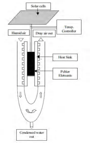
Referring to a researchby Raghied Mohammed Atta “Solar Water Condensation Using Thermoelectric Coolers” pages 142-145, 2011,the design used the semiconductor thermoelectric Peltier module to produce water from the basic laws of thermodynamics and applied to these devices just as they do to the conventional heat pumps, the absorptionrefrigerators and other devices involvedin the transfer of heat energy. This system’seffectiveness depends on the humidity level of the environment. A more humidity air will produce more water vapor and can produce up to one liter of condensed water per hour during the day.The solar cell unit used in this system is to drive the thermoelectric system and stored the energy to run the system at night. All mechanical interfaces between the objects are to be cooled as well as the ambient which is also a thermal interface. The humid air will enter the space to be cooled to condense the humid from air to water. The water will enter the water storage and the dry air is released to the ambient through Peltier (hot surface) for the purpose of cooling as shown in the diagram below.
The conservative favorable position of this kind of systems is still unclear because the installation costs are high. This system would be a long-term cost saving since the source is free and the sun oriented sub-system for the most part requires little maintenance. For the future, this system can be marketed to the appropriate areas to take advantage of the system that uses free source.
Figure 2.3: A water condensation system
2.3 Arduino
An Arduino is one of the most popular physical programmable circuit boards because it is more user friendly and easy to handle. Arduino also use the C language for the coding.The Arduino Mega 2560 is a microcontroller board and also known as the ATMega2560.
2.3.1 The Arduino Mega Specification
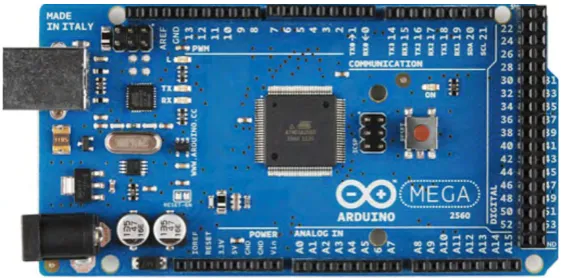
[image:20.595.197.478.412.551.2]Arduino Mega can have a 54-digital pins for the input/output pin. In the 54 pins, the 15 pins can be used as the Pulse Width Modulation (PWM). In the analog side, it can have 16 input pins anda USB connection, a power jack, an ICSP header and a reset button to contain everything needed to support the microcontroller.(Sram & Cycles, 2014)
Figure 2.4: The top view of Arduino Mega.
2.3.2 Pin Configurations
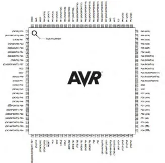
Figure 2.5: A Detailed PinIC in ATMEGA 2560
2.3.3 The Advantages of Arduino Mega
Microcontrollers are the main components to carry out a project but there are many types of microcontroller. In this project, Arduino Mega is the most suitable type of microcontroller to control the cooling and monitoring system. Some of the advantages of Arduino Mega are as follows:
I. has 70 input/output pins. II. 32 KB flash memory.
III. 2 KB SRAM.
IV. 1 KB EEPROM
V. four hardware serial ports.
2.4 Bluetooth for Communication System
2.4.1 Introduction
Bluetooth is an always-on, short-range radio hookup that resides on a microchip.Bluetoothisthe low-power short-range wireless standard for a wide range of devices.Bluetooth is intended to support an open-ended list of applications, including data, audio, graphics, and even video.(“Introduction to Bluetooth | Bluetooth Applications | InformIT,” n.d.)
A Bluetooth system uses the standard industry protocols to connect to the standard communication applications. In this example, a laptop computer is communicatedwith a wireless mouse, a personal digital assistant (PDA) and an access node using a single WPAN PCMCIA card. During the communication with the mouse, the laptop uses the standard RS-232 protocol. When transferring (exchanging) items between an address book stored in the laptop and an address book stored in the PDA, it uses the standard Object Exchange (OBEX) protocol. To connect to the Internet, the laptop connects through an access node to a router using a standard point-to-point protocol (PPP).(“Bluetooth Protocols,” n.d.)
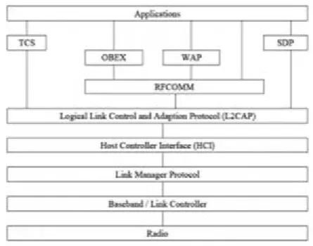
2.4.2 Bluetooth Structure
[image:23.595.240.463.246.421.2]The Bluetooth stack consists of seven layers. The Host Controller Interface(HCI) is the separating Hardware and Software and partially implemented in the software and hardware. The bottom layers are implemented in the hardware and those above are implemented in the software.(“Bluetooth System And Architecture,” n.d.)
Figure 2.6: A Bluetooth’s Architecture.
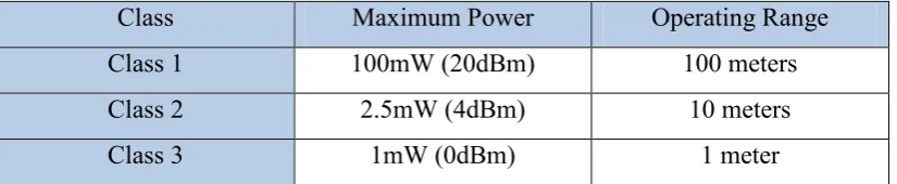
2.4.3 Power Class of Bluetooth
Bluetooth defines three main power classes used by the devices. Power control is used to keep the radiation within the limit so that the system works efficiently without interfering the neighborsof the Bluetooth devices. The power control algorithm is designed between the master and slave devices using a link management protocol.
Table 2.1: Power Class of Bluetooth
Class Maximum Power Operating Range
Class 1 100mW (20dBm) 100 meters
Class 2 2.5mW (4dBm) 10 meters
Class 3 1mW (0dBm) 1 meter
2.5 Software
An MIT App Inventor 2 will be used to monitor the temperature inside the lightning detection box. This application will be used to createan interface between the devices and the android phone.
2.5.1 MIT App Inventor 2
An MIT App Inventor 2is a software developed in Android Operating System which enable users to create their own applications like a monitoring system using a smartphone. The MIT App Inventor has a simple graphical interface allows inexperienced users to create applications without coding. The visual building block is easy to handle because it uses a drag-and-drop function on the running application.