DRAG COEFFICIENT REDUCTION OF A 30° YAW ANGLE CUBE SUBJECTED TO ACTIVE FLOW CONTROL DEVICE BY MEANS OF
NUMERICAL INVESTIGATION
JEDEDIAH KONG MENG HOI
This report is submitted
in fulfillment of the requirement for the degree of Bachelor of Mechanical Engineering (Thermal Fluid)
Faculty of Mechanical Engineering
UNIVERSITI TEKNIKAL MALAYSIA MELAKA
ii DECLARATION
I declare that this project report entitled “Drag Coefficient Reduction of a 30° yaw Angle Cube Subjected to Active Flow Control Device by Means of Numerical Investigation” is the result of my own work except as cited in the references
iii APPROVAL
I hereby declare that I have read this project report and in my opinion this report is sufficient in terms of scope and quality for the award of the degree of Bachelor of Mechanical Engineering (Thermal Fluid).
iv DEDICATION
v ABSTRACT
vi ABSTRAK
vii ACKNOWLEDGEMENT
I would like to express my profound appreciation to my supervisor Dr. Cheng See Yuan for his guidance, advice, as well as support provided to me throughout this research. Although there is slight dispute as well as disagreement among us throughout this research, Dr. still manage to provide a clear path and guidance for me. I sincerely appreciate it.
I would also love to express my gratitude to my friends and lecturers that have provided me with solutions and advices at difficult times faced throughout this research. Your presence and help had always been my motivation to preserve.
Not to forgotten, my family members that have been always supporting me in term of financial and mental, I will not be here without your support.
This research was supported by Universiti Teknikal Malaysia Melaka (UTeM). I thank UTeM for the support in terms of resources provided help completion of this research. Faculty of mechanical engineering (FKM) have been a big contribution for the success of this project. Besides providing computer and software through laboratory located in Fasa B, FKM have also provide seminars, lecturers and lab assistant support to ensure this research is successfully completed.
viii TABLE OF CONTENT
CHAPTER CONTENT PAGE
DECLARATION ii
SUPERVISOR’S APPROVAL iii
DEDICATION iv
ABSTRACT v
ABSTRAK vi
ACKNOWLEDGEMENT vii
TABLE OF CONTENT viii
LIST OF TABLES x
LIST OF FIGURES xi
LIST OF ABBREVIATIONS xiv
LIST OF SYMBOLS xv
CHAPTER 1 INTRODUCTION 1
1.1 Background 1
1.2 Problem Statement 3
1.3 Objective 3
1.4 Scope Of Project 4
CHAPTER 2 LITERATURE REVIEW 5
2.1 Bluff-Body Aerodynamics 5
2.2 Cube Flow 6
2.3 Synthetic Jet 7
2.4 Plasma Actuator 10
2.5 Moving Surface Boundary-Layer Control 13
CHAPTER 3 METHODOLOGY 16
3.1 Introduction 16
3.2 Geometry Drawing 18
3.3 Meshing 19
ix
3.5 Post-processing 28
CHAPTER 4 RESULTS AND DISCUSSION 30
4.1 No Flow Control Device 30
4.2 MSBC Device 32
4.3 Synthetic Jet 35
4.4 Plasma Actuator 38
4.5 Grid Independent Test 41
4.6 Data and Comparison 43
4.7 Result Validation 45
4.8 Pressure Fluctuation 46
CHAPTER 5 SUMMARY 48
5.1 Conclusion 48
5.2 Future Work 49
REFERENCE 50
LIST OF APPENDIX 54
x LIST OF TABLES
TABLE TITLE PAGE
xi LIST OF FIGURES
FIGURE TITLE PAGE
1.1.1 Variation of Drag Force on a Body 1 2.2.1 Instantaneous Velocity Contour with Streamline of B/D=2.0 6 2.2.2 Streamline of Air Flow across a 30º Yawed Cube 7 2.3.1 Schematic Diagram of Synthetic Jet 8 2.4.1 Schematic Diagram of SDBD Plasma Actuator 11
2.4.2 Top View of Plasma Discharge 15
2.5.1 Iso Surface for Natural Case (a) and Controlled Case (b) in the Case of 30◦ Yaw Angle, Top View
15
2.5.2 Iso Surface for Natural Cases (a) and Controlled Case (b) in the Case of 30◦ Yaw Angle, Side View
13
3.1.1 Flow Chart of CFD Simulation 17
3.2.1 Geometry of 30° Yaw Cube 18
3.2.2 Location of Synthetic Jet Actuator’s Orifice 18
3.3.1 Meshed Product of Cube 19
3.4.1 Location of Rotating Cylinder 21
3.4.2 UDF Code for Synthetic Jet Actuator (clockwise side, x-axis) 22 3.4.3 UDF Code for Synthetic Jet Actuator (clockwise side, y-axis) 22 3.4.4 UDF Code for Synthetic Jet Actuator (counter-clockwise side,
x-axis)
23
3.4.5 UDF Code for Synthetic Jet Actuator (counter-clockwise side, y-axis)
23
xii 3.4.8 UDF Code for Plasma Actuator (counter-clockwise side,
x-axis)
27
3.4.9 UDF Code for Plasma Actuator (counter-clockwise side, y-axis)
28
4.1.1 Diagram of Velocity Contour around a Cube with No Active Flow Control Device
30
4.1.2 Diagram of Pressure Contour around a Cube with No Active Flow Control Device
31
4.1.3 Diagram of Velocity Vector around a Cube with No Active Flow Control Device
31
4.1.4 Graph of Drag Coefficient against Time for Simulation with No Flow Control Device
32
4.2.1 Diagram of Velocity Contour around a Cube subjected to MSBC Device
33
4.2.2 Diagram of Pressure Contour around a Cube subjected to MSBC Device
34
4.2.3 Diagram of Velocity Vector around a Cube subjected to MSBC Device
34
4.2.4 Graph of Drag Coefficient against Time for Simulation with MSBC Device Implemented on a Cube
35
4.3.1 Diagram of Velocity Contour around a Cube subjected to SJ 36 4.3.2 Diagram of Pressure Contour around a Cube subjected to SJ 36 4.3.3 Diagram of Velocity Vector around a Cube subjected to SJ 37 4.3.4 Graph of Drag Coefficient against Time for Simulation with SJ
Device Implemented on a Cube
37
4.4.1 Diagram of Velocity Contour around a Cube subjected to PA 39 4.4.2 Diagram of Pressure Contour around a Cube subjected to PA 39 4.4.3 Diagram of Velocity Vector around a Cube subjected to PA 40 4.4.4 Graph of Drag Coefficient against Time for Simulation with
PA Device Implemented on a Cube
40
4.5.1 Scale of 1.5 𝑐𝑚 : 20 𝑚𝑚 View for Mesh Generated Around a Cube Used for Grid Independence Test
xiii 4.5.2 Scale of 1.5 𝑐𝑚 : 75 𝑚𝑚 View for Mesh Generated Around a
Cube Used for Grid Independence Test
42
4.5.3 Scale of 1.5 𝑐𝑚 : 175 𝑚𝑚 View for Mesh Generated Around a Cube Used for Grid Independence Test
42
4.7.1 Iso-surface of the Time-averaged Streamwise Velocity 𝑈=0 for No Flow Control Device Case
46
4.8.1 Graph of Pressure Coefficient against Time Step for Synthetic Jet Implemented on a Cube
xiv LIST OF ABBEREVATIONS
MSBC Moving Surface Boundary-Layer Control SJ Synthetic Jet
PA Plasma Actuator
xv LIST OF SYMBOL
𝑓 = Frequency
𝐷𝐶 = Diaphragm Diameter 𝐷0 = Orifice Diameter
∆ = Amplitude 𝑡 = Time
𝑢̃0(𝑡) = Fluid leaving Orifice Velocity
𝐶𝐷 = Drag Coefficient 𝐹𝑋 = Drag Force 𝐴𝑟𝑒𝑓 = Reference Area
1 CHAPTER 1
INTRODUCTION
1.1 BACKGROUND
[image:16.595.153.493.626.731.2]In general, there are only two distinct types of body, which are streamlined body and bluff body. The major property differentiating these bodies are the type of drag force dominating the body. Viscous drag dominates the drag force of a streamlined body whereas pressure drag dominates the drag force of a bluff body. For a given fixed frontal area and velocity flowing through both types of body, a bluff body will produce higher drag force as compared to a streamline body. This results in many researches done to reduce the drag force for a bluff body. As fluid flows across a bluff body, a large flow separation tends to occur and this will lead to the formation of wake region at the leeward side of the body which prevents pressure from recovering. A larger wake will prevent more pressure recovery from recovering and this will lead to greater pressure drag (Srinivas, 2016). Figure 1.1.1 below shows the variation of drag forces that act on a body.
2 The modification of wake region is one of the common technique used to reduce the bluff body’s drag force. There are two ways to modify the wake region of a body, by using an active flow control device or passive flow control device. Passive control usually utilizes the method of geometry modification and this devices are always operating, regardless of the need. In active flow control method, a device is used to inject extra energy or momentum to the flow. In some cases, active flow control operates only when needed, making it more desirable compared to passive flow control in term of performance. However, additional cost and effort is needed for active flow control. There are three commonly used devices in the application of active flow control which are Synthetic Jet (SJ), Plasma Actuator (PA) and Moving Surface Boundary layer Control (MSBC). These devices have one advantage compared to other device which is it produce zero-net-mass-flux. A research have been done by (Han et. al., 2013) which successfully shown that drag coefficient of a cubical shaped object is reduced with the use of Moving Surface Boundary layer Control (MSBC). On the other hand, a study too have been done by (Pescini et. al., 2016) using plasma actuator to reduce the displacement and momentum thickness of the boundary layer’s separated region which in turn reduces the shape factor value.
3
1.2 PROBLEM STATEMENT
As a flow passes through a cube, the pressure drag dominates the drag force, which means cube is a bluff body. According to a research done by (Xingsi and Siniša, 2013), the use of MSBC technique reduced the drag force of a 30° yawed cube by up to 44%. However, as many research have been done by using individual active flow control device to test the drag reduction of a certain shape, not many research have been done to compare the performance of different active flow control device. In this study, simulation will be done to compare the drag reduction result by using SJ and PA with MSCB on a 30° yawed cube. The positioning for the placement of these two devices will be at the exact same spot at which the MCBS is positioned, which is at the both corners of the windward side of the cube. A fixed angle of 45º actuation from the actuation outlet is implemented for both SJ and PA. The same boundary condition will be used.
1.3 OBJECTIVE
The objectives of this project are:
1) To numerically investigate the effect of active flow control devices on flow of a 30º yaw cube.
4 1.4 SCOPE OF PROJECT
The scopes of this project are:
1) Simulating flow around a cube with Reynolds number of 6.7×10⁴.
2) Using 4 magnitudes of Synthetic Jet maximum actuation speed which are
1 𝑚 𝑠⁄ , 2 𝑚 𝑠⁄ , 3 𝑚 𝑠⁄ and 4 𝑚 𝑠⁄
3) Using 4 magnitudes of Plasma Actuator force value which are
1𝑚𝑁 𝑚⁄ , 2𝑚𝑁 𝑚⁄ , 3𝑚𝑁 𝑚⁄ and 4𝑚𝑁 𝑚⁄ .
4) Comparing the drag coefficient reduction around a cube after the cube is equipped with MSBC device, Synthetic Jet, and Plasma Actuator.
5 CHAPTER 2
LITERATURE REVIEW
2.1 Bluff-Body Aerodynamics
6 2.2 Cube Flow
In a research done by Ying et. al. (2012), by using Reynolds number of 21400, the aerodynamic patterns of rectangular cylinders with various aspect ratios are determined. From the results obtain, Ying categorized the patterns into three types, namely separated type (B/D=1.0 and B/D=2.0), intermittently reattached type (3.0<B/D<6.0) and fully reattached type (7.0<B/D<10.0). Thus, a cube can be categorize as the same flow as rectangular cylinder with aspect ratio of B/D=2.0. Ying also mentioned that the three-dimensional properties of the flow will become more significant as the location from the separation point is further from the leading point.
[image:21.595.136.502.485.625.2]From Figure 2.2.1 below, there are recirculating vortices generated around the upper and lower surfaces of the wall, with flow separation at the leading edge remain unattached to the wall. Not only that, the vortex generated behind the cross-section is far away from the back surface, resulting in relatively small Strouhal number.
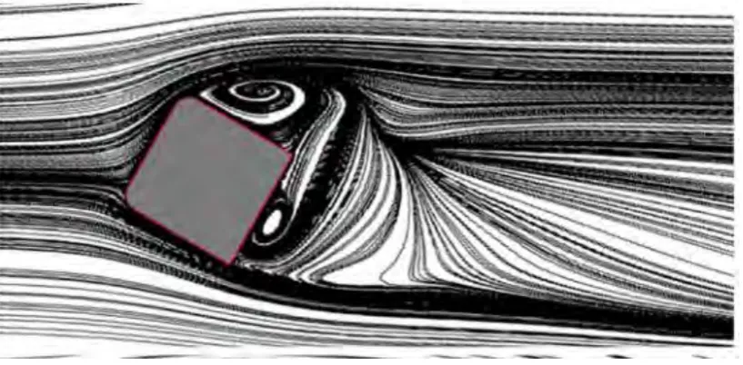
7 In another research done by Xingsi and Siniša (2012) on the flow across a 30º yawed cube, based on the streamline flow diagram, we can deduce that the pressure is maximum at the front left edge of the cube. In Figure 2.2.2, as the flow travel through the cube to the right side of the cube, there is a great pressure drop. This happens as the flow starts separating. The difference in pressure at the front of the cube and the side of the cube causes large drag force.
Figure 2.2.2 Streamline of Air Flow across a 30º Yawed Cube (Xingsi and Siniša, 2013)
2.3 Synthetic Jet
8 of SJ actuator have been discussed by Macovei and Florin (2014). Mocevei and Florin (2014) mentioned two major steps in the working mechanism. Firstly, outer air is sucked into the cavity through the orifice when the membrane moves downward. The second step is when the membrane moves upward, causes the fluid to be discharged through the orifice. Vortex ring will be generated as the fluid discharge through the orifice with sufficient energy. Upon continuous upwards and downwards movement of the membrane, generation of vortices column will occur. The vortices column add momentum to the outer fluid without adding mass flux. Mocevei and Florin (2014) also stated that SJ is available for various application due to its wide range of time and length scale.
Figure 2.3.1Schematic Diagram of Synthetic Jet (Macovei and Frunzulica, 2014)
9 frequencies in a specific range. This causes breaking down of the large-scale flow structure correlated with detached shear flow into smaller-scale flow (Tang et. al., 2013)
The periodic motion of diaphragm in the actuator driven by piezoelectric disc produce an unsteady forcing flow (Glezer & Amitay, 2002), which definitely differ from a steady forcing flow. Although this flow is way more complex as compared to a steady forcing flow, it presents three major advantages: smaller order of power requirement magnitude, possible decoupling of actuators from main propulsive system, and SJ are small-sized, light, and autonomous (Greenblatt & Wygnanski 2000).
According to Arun and Ankit (2015), it is expected that maximum jet velocity affects the jet penetration effect. Thus, taking the same average velocity of uniform profile (steady blowing) and parabolic profile (unsteady blowing), a parabolic profile will have the advantage of having higher maximum velocity at the jet centre. In turn, a parabolic profile jet will be able to penetrate deeper as compared to a uniform profile jet. Arun and Ankit (2015) also stated that while there are backflow along the wake centreline during unsteady forcing flow, the effect is negligible. Not only that, Arun and Ankit (2015) discover that upon taking jet momentum into consideration, the drag coefficient is greatly reduced.