Developing a backplane solution for the TCS PCC : thesis submitted in complete fulfilment of the requirements for the Master of Engineering
200
0
0
Full text
(2) MASSEY UNIVERSITY NEW ZEALAND DEVELOPING A BACKPLANE SOLUTION FOR THE TCS PCC. MASTERS THESIS Thesis submitted in complete fulfilment of the requirements for the Master of Engineering. Author: Thomas Johannes Laurentius Leijen [email protected]. Supervisor: Dr Frans Weehuizen [email protected]. 1.
(3) 2.
(4) 3.
(5) Acknowledgements Thanks to my mentor and lecturer Frans Weehuizen for being supportive, inspirational and educational throughout my time at Massey University. Thanks to my parents Herbert and Cunie Leijen for providing financial support and motivation to keep excelling throughout my education at Massey University. Thanks to TCS and their staff for providing a great study environment and providing me the opportunity to gain valuable industry experience alongside a valuable education.. 4.
(6) Abstract TCS is company that specialises in systems integration and development of products for industrial application. Their flagship product for distributed control is the CPU5. This project covers the design and development of a backplane solution to solve the limitation of the CPU5 that it only has a limited number of inputs and outputs. The next iteration of the CPU5, is to be called the PCC. Background research was carried out into the needs of TCS and their target markets. The IEC61499 standard, Windows CE platform and ISaGRAF software environment were also investigated. The project planning was analysed to gain an understanding of R&D project planning. This project concluded that it was important to be able to make changes to the plan as the project proceeds so that it can still be completed by the deadline. TCS had set the limitation that the backplane protocol must be a serial bus. Various different types of serial bus were investigated including CAN, USB, Light Peak (optical) and EIA485. The bus selected was a CAN bus with a custom protocol. Research was carried out into the operation of existing bus drivers and protocols such as DeviceNet and CANOpen to determine an appropriate protocol for a serial bus based backplane. Software was developed to manage devices attached to the backplane. Hardware and software for a digital I/O module was developed. Various ways of updating the I/O were investigated, an event-based and cyclic updating method was implemented with an adjustable debounce time to maximise performance and robustness. Hardware and software for a serial port module was developed. A major challenge faced was to transmit a stream based protocol across a frame based CAN backplane. Software for an Ethernet module was developed. Software design included development of an NDIS compatible miniport driver for Windows CE and software for the slave module. To demonstrate that the PCC is an effective platform for distributed control, a test setup was created to be shown at a trade show in Nuremberg. The trade show setup was fully programmed in compliance with the IEC61499 standard and demonstrated the power of the PCC.. 5.
(7) Contents Acknowledgements................................................................................................................................. 4 Abstract ................................................................................................................................................... 5 Introduction ............................................................................................................................................ 9 Aim ........................................................................................................................................................ 10 Objective ............................................................................................................................................... 10 1.. 2. 3. 4. Background Research.................................................................................................................... 11 1.1. Introduction .......................................................................................................................... 11. 1.2. TCS ltd ................................................................................................................................... 12. 1.3. The IEC 61499 standard ........................................................................................................ 13. 1.4. Windows CE 5 ....................................................................................................................... 17. 1.5. ISaGRAF 5.0 ........................................................................................................................... 19. 1.6. Conclusion ............................................................................................................................. 21. Project planning ............................................................................................................................ 22 2.1. Introduction .......................................................................................................................... 22. 2.2. Developing the initial timeline .............................................................................................. 22. 2.3. Timeline update in July ......................................................................................................... 23. 2.4. Recommendations ................................................................................................................ 24. 2.5. Discussion.............................................................................................................................. 24. 2.6. Conclusion ............................................................................................................................. 24. Backplane communications protocol selection ............................................................................ 25 3.1. Introduction .......................................................................................................................... 25. 3.2. Criteria................................................................................................................................... 25. 3.3. Reason for using a serial bus topology ................................................................................. 26. 3.4. List of potential data bus options ......................................................................................... 27. 3.5. First round of eliminations .................................................................................................... 31. 3.6. Possible communications protocols ..................................................................................... 32. 3.7. Recommendations ................................................................................................................ 41. 3.8. Discussion.............................................................................................................................. 42. 3.9. Conclusion ............................................................................................................................. 43. Windows CE backplane driver development ................................................................................ 44 4.1. Introduction .......................................................................................................................... 44. 4.2. Background research ............................................................................................................ 45. 4.3. Initial design ideas ................................................................................................................. 48 6.
(8) 5. 6. 4.4. Examples of similar device installation procedures .............................................................. 49. 4.5. Device installation routine plans .......................................................................................... 54. 4.6. Registry Setup ....................................................................................................................... 58. 4.7. Message prioritisation .......................................................................................................... 59. 4.8. Backplane driver software development .............................................................................. 60. 4.9. Error logging .......................................................................................................................... 70. 4.10. Fragmentation....................................................................................................................... 72. 4.11. Multithreading ...................................................................................................................... 74. 4.12. Slave microcontroller software ............................................................................................. 76. 4.13. Recommendations ................................................................................................................ 82. 4.14. Discussion.............................................................................................................................. 84. 4.15. Conclusion ............................................................................................................................. 84. Digital I/O module development .................................................................................................. 85 5.1. Introduction .......................................................................................................................... 85. 5.2. Hardware used for initial development ................................................................................ 85. 5.3. Windows CE stream interface driver .................................................................................... 88. 5.4. Software Development ......................................................................................................... 90. 5.5. Slave microcontroller software ............................................................................................. 94. 5.6. ISaGRAF software development ........................................................................................... 99. 5.7. Hardware development ...................................................................................................... 102. 5.8. Performance testing............................................................................................................ 104. 5.9. Recommendations .............................................................................................................. 105. 5.10. Discussion............................................................................................................................ 106. 5.11. Conclusion ........................................................................................................................... 106. Serial port module development ................................................................................................ 107 6.1. Introduction ........................................................................................................................ 107. 6.2. Hardware used for initial testing ........................................................................................ 107. 6.3. Layered drivers .................................................................................................................... 108. 6.4. COM MDD and PDD interaction.......................................................................................... 109. 6.5. Software development ....................................................................................................... 110. 6.6. Data transmission ............................................................................................................... 114. 6.7. Slave microcontroller software development .................................................................... 120. 6.8. ISaGRAF software development ......................................................................................... 121. 6.9. Hardware development ...................................................................................................... 123 7.
(9) 7. 8. 6.10. Performance testing............................................................................................................ 128. 6.11. Recommendations .............................................................................................................. 131. 6.12. Discussion............................................................................................................................ 132. 6.13. Conclusion ........................................................................................................................... 132. Ethernet port module development ........................................................................................... 133 7.1. Introduction ........................................................................................................................ 133. 7.2. Hardware used for testing .................................................................................................. 133. 7.3. Network driver architectures .............................................................................................. 134. 7.4. Ethernet driver software development .............................................................................. 136. 7.5. Slave microcontroller software development .................................................................... 160. 7.6. Data transmission ............................................................................................................... 172. 7.7. Performance testing............................................................................................................ 174. 7.8. Recommendations .............................................................................................................. 179. 7.9. Discussion............................................................................................................................ 180. 7.10. Conclusion ........................................................................................................................... 180. Nuremberg show setup (PCC Test and Demonstration) ............................................................. 181 8.1. Introduction ........................................................................................................................ 181. 8.2. Hardware setup................................................................................................................... 182. 8.3. SCADA screen ...................................................................................................................... 184. 8.4. IEC61499 ............................................................................................................................. 185. 8.5. Public reaction .................................................................................................................... 191. 8.6. Recommendations .............................................................................................................. 192. 8.7. Discussion............................................................................................................................ 192. 8.8. Conclusion ........................................................................................................................... 192. Project Discussion ............................................................................................................................... 193 Project Conclusion .............................................................................................................................. 194 Bibliography ........................................................................................................................................ 195 Glossary ............................................................................................................................................... 198. 8.
(10) Introduction TCS is a systems integrator as well as a developer of products for industrial control. TCS has over 10 years of history developing distributed control products; their current flagship product is the CPU5. The CPU5 was developed as a platform for the ISaGRAF software. ISaGRAF is a control software environment that supports the IEC61131 (ladder logic) and IEC61499 (distributed control using function blocks) standards. Although TCS has sold many CPU5 modules, they have not yet captured the market share they intended to. A few reasons for the CPU5 not being as successful as anticipated include: cost, size, lack of inputs and outputs (I/O) and component availability. This project is part of the next major design iteration of the CPU5, the development of the CPU6. To give the CPU6 more appeal in a market where devices are named by acronyms such as PLC (Programmable Logic Controller), it has been given the name PCC which stands for “Programmable Cell Controller”. The PCC will be built with newer components so that it is smaller, more powerful and cheaper but will run a similar software platform (ISaGRAF installed on a Windows CE platform) to that installed in the CPU5. One significant difference between the CPU5 and the PCC will be that the PCC will have a system where additional I/O modules can be attached to the controller in a similar way to how traditional programmable logic controllers (PLCs) using a backplane for I/O modules. TCS is already experienced in the development of embedded controllers so they will be in charge of developing the main controller as it will only be a slight iteration from the CPU5. Because of its complexity, TCS staff will also develop the hardware for the Ethernet module. The part of the project that is completely new to TCS is the development of the backplane hardware and software to allow additional I/O modules to be attached to the PCC controller. The parts of this project discussed in this thesis include: carrying out background research, developing a project plan, selecting a communications protocol for the backplane, developing hardware and software for the backplane, developing hardware and software for a digital I/O module, developing hardware and software for a serial port module, developing software for an Ethernet port module and demonstrating the project running an IEC61499 compliant program at a trade show.. 9.
(11) Aim Develop and test hardware and software for a backplane solution that allows extra I/O to be attached to TCS’s latest iteration of their flagship distributed control product (the PCC). The backplane solution developed must be as flexible as (or more flexible than) current PLC rack and remote I/O solutions. Hardware and software to be developed include a digital I/O module, a serial port module and an Ethernet/IP port module. The modules developed are some of the most commonly available types and will provide platforms from which it is possible to develop additional types of I/O modules. The software developed must support Windows CE and the ISaGRAF software and be compatible with the latest in industrial control standards. The backplane and the I/O modules will be put through various performance tests to determine whether they are ready to be implemented in an industrial situation and which parts will need to be focussed on in future development. The effectiveness of the project will be tested by developing a sample application for a real-life industrial situation and demonstrating this working on the newly developed hardware at a trade show in Nuremberg.. Objective Complete the tasks listed in the aim within 12 months using research resources sourced from Massey University and any other resources sourced from TCS that fit within the project budget. Although the final goal is to produce a product that can be released into industry, care needs to be taken that the project is also academically relevant and that emphasis is put on parts of the project that fall outside TCSs areas of expertise. Priority is to be put on the parts of the project that fall outside TCSs areas of expertise such as the development of the backplane, the I/O modules and performance testing. Other features, such as product documentation, error reporting and some hardware development, that are needed to make the project ready for release into industry will be of a lower priority.. 10.
(12) 1. Background Research 1.1. Introduction. This section includes all the background research carried out relevant to the project. It contains a description of the company sponsoring the project, a description of the IEC61499 standard which is relevant to the control methodology that the project has to be compatible with, a description of Windows CE which is the operating system that the software developed has to be compatible with and a description of ISaGRAF which is the program that will be running all the control algorithms that drive the I/O modules.. 11.
(13) 1.2. TCS ltd. About the company TCS is a New Zealand owned and operated industrial automation and technology company that has been operating for over 25 years. Their customers are involved in a wide range of industries such as dairy, food, beverage, meat, timber, paint, quarries and fertiliser and have projects ranging from standalone equipment to complex fully integrated plants. TCS has a strong reputation for industrial communications that interface to a wide range of industrial devices and can also link with management network systems. TCS areas of expertise are: . Industrial automation Industrial communications Management database integration Production traceability Electronic micro-processor based technology and products Distributed intelligence. There are 3 interrelated engineering teams within TCS: . . . The Industrial Automation team specialises in industrial automation, communications, traceability and management database integration using industrial hardened devices such PLC, SCADA / HMI and industrial communications technologies. The Product Development team is a highly innovative team that designs, develops and builds microprocessor based technology for a range of agricultural and industry applications, for end users or for Original Equipment Manufacturers (OEMs). The team is continually researching and developing new technologies. The Manufacturing team assembles, tests and quality controls all TCS products. (TCS (NZ) Ltd) The CPU5 project TCS has been developing distributed control products for over 10 years. At the start of this project TCS’s flagship product for distributed control was the CPU5. The CPU5 is an industrial thin client controller running ISaGRAF on a Windows CE 5.0 platform. The CPU5 is equipped with the following ports: Ethernet, CAN, RS232, RS422 and RS485. There is also a version with Wi-Fi. The CPU5 however has a number of limitations that are preventing TCS from obtaining the market share they hoped to get with their distributed products. These limitations include: . Price: The hardware and components used are too expensive compared to similar products on the market. Component availability: The PXA255 microcontroller used in the CPU5 is becoming obsolete and will not be available on the market for much longer. Cost of adding I/O modules: TCS currently does not produce I/O modules so has to purchase DeviceNet modules from other vendors to add extra I/O.. (Meek, 2010) 12.
(14) 1.3. The IEC 61499 standard. Why it is being developed The trend of growth in industrial control systems is a movement toward more integrated and agile systems. With concepts such as lean manufacturing becoming more popular it is important that systems are able to rapidly change from one production process to another. Industrial control systems therefore need to be easier to adapt and be changed in a quick manner. Integrating plant floor control with logistics, accounting and business management systems plays a very important role in improving the agility of a system/business. Globalisation of production is also becoming more common so there are developing needs for integrating production systems in one country with offices in other countries. The well-established standard for industrial automation is the IEC61131-3 standard (full description of this protocol is beyond the scope of this project) which has still got several flaws, these are listed below: . Not distributable over multiple resources. Execution order is not always clearly defined. It is not flexible enough, not all blocks can be connected directly etc. IEC61131 is of a scanned nature so it cannot be distributed over large networks.. The IEC61499 standard has been developed as a logical development of the IEC61131-3 standard. One of the major benefits of the IEC61499 standard is that function blocks can be understood by mechanical, electronic and software engineers: They can be seen as components of a physical system, of an electronic circuit, or as objects of an object oriented program. (Lewis, Introduction, 2008) Present standard The IEC61499 standard consists of 4 main parts, these are: . . The system model. The system model describes the relationships between communicating devices and applications. It describes how devices are connected together and what sort of communication links they use. The system model also shows how applications (software) are divided amongst the resources (hardware) in the system. The resource model. The resource model encompasses the physical resources in a production system, these resources range from smart sensor controllers to administration servers. The resource model describes how the controllers are connected to the machinery and provides communication interfaces between the various resources in a production system.. 13.
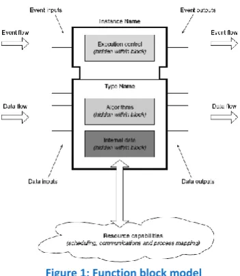
(15) . . The application model. The application model encompasses the software, in the case of the IEC61499 standard it is a network of interconnected function blocks. An application can be distributed over multiple resources. A sub application is a type of function block that is constructed from networks of basic and composite function blocks designed to provide a re-usable part of an application that can be distributed over many resources. The function block model. This is the core of the standard. A function block can represent anything from a single sensor in a plant to a complete division of a company. A function block has the following features: Type name and instance name Event input(s) Event output(s) Data input(s) Data output(s) Internal variables Behaviour is defined in terms of algorithms and state information, these algorithms can be text based, or they can be in function block diagram format.. Figure 1: Function block model. In the future it is anticipated that a function block diagram will be able to be compiled into a textual format which is legible and understandable by almost anyone, even people without programming experience, this will make understanding of processes, improvement and fault finding much easier. (Lewis, IEC 61499 models and concepts, 2008). 14.
(16) Current research An article written by Jeffrey Yan and Valeriy Vyatkin discusses an implementation of IEC61499 on an airport baggage handling system (BHS). Baggage handling systems consist of many interconnected conveyors that are laid out according to airport requirements, this layout is likely to change over time as new bag routes are developed, equipment is upgraded or equipment malfunctions occur. Traditional BHS are controlled by a monolithic control program based in a centralised controller unit; this means that the program will need to be changed with every slight change to the conveyor layout. The researchers suggest a method using IEC61499 which will greatly improve the control methodology of the baggage handling system. To prove this they used a software package by ICS Triplex called ISaGRAF (this software is discussed later in this report). A number of smart conveyors (conveyor with control and sensing functionality) were set up with the ISaGRAF runtime. Using the ISaGRAF Workbench tool, function blocks were developed for each individual conveyor and these were networked together to form a model of the entire conveyor system. In IEC61499 terms, the function block representing a conveyor in a BHS, receives an event input when a bag is passed onto the conveyor, bag specific data, such as destination, is also passed to the block through the event inputs, when the bag leaves the conveyor, the data and an event is passed to the next conveyor. Because a BHS can be quite a complex system, it is likely that there are multiple ways to transport a bag from the source to the destination, this has the benefits of redundancy and also efficiency but can get quite complex to control. Where traditional systems would have a central unit observing the state of the system, or even just fixed routes, Yan and Vyatkin suggest implementing a Bellman Ford algorithm (similar to that used to route IP packets over the internet). Using the Bellman Ford algorithm, individual function blocks (representing conveyors with multiple outputs) can maintain an up to date routing table (by passing data to the function blocks before and after them) to automatically determine where to send the bag as to ensure it reaches its destination in the fastest possible way. (Yan & Vyatkin, 2010) The benefits of the IEC61499 BHS control methodology proposed by Yan and Vyatkin include: . . . Decentralised processing adds redundancy to a system; no longer will the whole system fail if one part of it fails. Increased baggage transfer speeds, with the modules re-calculating the fastest route (using the Bellman Ford algorithm) at regular intervals, bags will always reach their destination in the fastest possible way. Ease of re-arranging the BHS or adding extra routes. It will simply be a case of adding a few extra function blocks representing the new conveyors/apparatus using the Workbench tool. The Bellman Ford algorithm will then automatically recalculate all the routes through the system. Instead of viewing the control software as several pages of structured text or ladder logic, it is represented in the much more intuitive form of function blocks. Because bag specific data is maintained within the database of the individual conveyors data access is a lot faster and there is no need for large amounts of storage in a central database.. 15.
(17) The concepts researched by Yan and Vyatkin can have a wide range of applications other than baggage handling in industries ranging from materials handling to food processing.. 16.
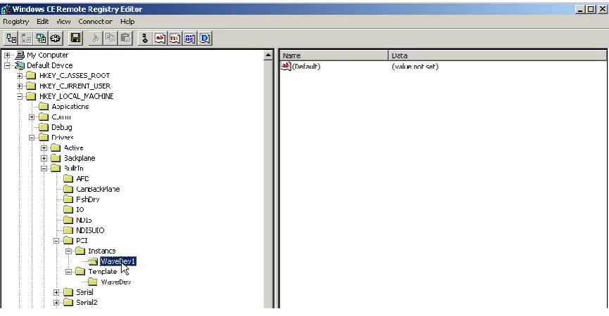
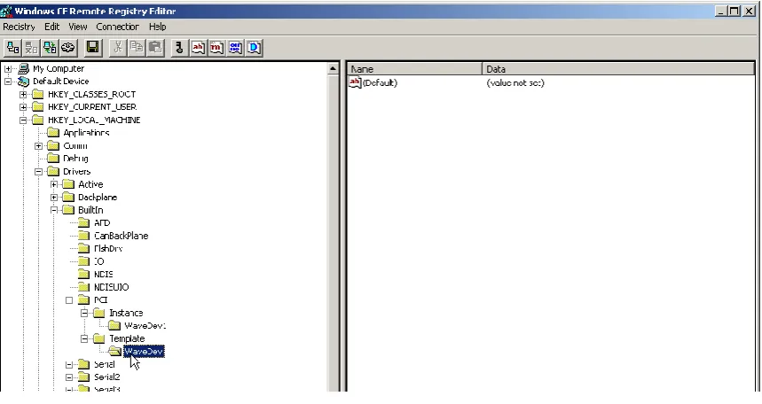
(18) 1.4. Windows CE 5. “Microsoft® Windows® CE 5.0 is an open, scalable, 32-bit operating system (OS) that integrates reliable, real time capabilities with advanced Windows technologies. Windows CE allows one to build a wide range of innovative, small footprint devices. A typical Windows CE–based device is designed for a specific use, it often runs disconnected from other computers, and requires a small OS that has a deterministic response to interrupts. Examples include enterprise tools, such as industrial controllers, communications hubs, and point-of-sale terminals, and consumer products, such as cameras, Internet appliances, and interactive televisions.” (Microsoft) The quote states that the Windows CE operating system “is an open, scalable, 32-bit operating system”; the operating system is in fact not completely open source. Only the parts that Microsoft has determined are relevant for developers of embedded devices, such as hardware interfaces are open source. Brief history Windows CE was first released as a scaled down version of Windows 95 in November 1995. The project from which Windows CE originated was the WinPad project. The WinPad project was developed to drastically change the way users interacted with handheld devices, unfortunately “ahead of its time” features such as handwriting recognition could not be supported due to hardware limitations at the time, the death of this project led to the introduction of the Windows CE project. Windows CE 5.0 was announced at the start of 2003 and released in Q3/4 of 2004. The current version of Windows CE is version 6.0. Version 7.0 is however on the horizon with an anticipated release date of Q3/4 2010 (Tilley, 2001) TCS is currently using Windows CE 5.0 as it was the latest version when they started using it to develop drivers and software for the CPU5 project. Platform Builder “Microsoft® Platform Builder for Windows CE is an integrated development environment (IDE) for building customized embedded operating system (OS) designs based on the Microsoft Windows® CE OS. Platform Builder comes with all development tools necessary for one to design, create, build, test, and debug a Windows CE–based OS design. The IDE provides a single integrated workspace where one can work on both OS designs and projects.” (Microsoft) Platform builder is the software package used by TCS to write software and drivers for their windows CE operating system. Platform Builder contains all the source code for the windows CE operating system and allows the development of applications and board specific source code (board specific source code is known as a BSP – Board Support Package). Platform builder contains the source code for many common hardware drivers and allows these to be copied and customised to suit different types of hardware. For this project we will be creating a new BSP for the CPU6 (PCC) hardware by modifying and adding to the BSP made for the CPU5 project. Platform builder also contains many tools for debugging such as the Remote Registry Editor (allows one to observe and edit the Windows CE registry) and the Remote Kernel Tracker (allows one to see which software routines/threads are being executed in the CPU).. 17.
(19) Current uses Windows CE is commonly known to be used in the PDA (Personal Digital Assistant), handheld computer and mobile phone markets. Because Windows CE is a customisable RTOS (Real Time Operating System), it is however used in many more markets. A few examples of applications for Windows CE, outside of the aforementioned markets, include GPS (Global Positioning Satellite) navigation systems, automotive display units, remote storage, media players (set top and handheld), POS (point of sale) devices industrial HMI displays and industrial controllers. The advantage of using a Windows CE based device over using a PC with a traditional Windows operating system is that it can be made a lot more lightweight and the ability to create high priority system interrupts allows Windows CE devices to be a lot faster and a lot more reliable.. 18.
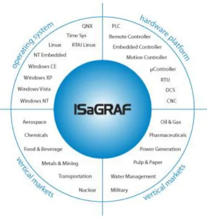
(20) 1.5. ISaGRAF 5.0. About ISaGRAF “ISaGRAF is a control software environment that enables you to create local or distributed control systems. It offers a combination of a highly portable, robust control engine (Virtual Machine) and an intuitive application development environment (Workbench). ISaGRAF 5 is the world's first automation software to be compliant with both IEC 61131 and IEC 61499 industrial standards. This leading-edge software is comprised of a powerful set of new features that promise to change the way you build your control systems.” (ICS Triplex). Figure 2: ISaGRAF market coverage (ICS Triplex). The figure above shows how ISaGRAF works in combination with various products and markets. ISaGRAF can be installed on any of the hardware platforms listed but the platform must be running one of the listed operating systems, the resultant PLC can then be used to automate systems in any of the listed markets. TCS has decided to, to best suit their target markets, install ISaGRAF on a microcontroller running the Windows CE operating system.. 19.
(21) ISaGRAF 61499 environment While designing the ISaGRAF IEC61499 environment, ICS Triplex research engineers kept the following factors in mind: . . . . The IEC61499 implementation would complement the existing IEC61131 implementation so that both IEC61131 and IEC61499 could co-exist in the system. The state machine used in the controller would use the IEC61131 language with a few slight changes to allow IEC61499 to function. This means that design engineers can still use ISaGRAF without needing to learn a new language. The basic logic engine would be cyclic, like the traditional PLC logic implementation. This was done to preserve determinism and stability and to entice other automation vendors to adopt the standard. The producer consumer communication model was adopted because it can be implemented on any communication stack such as Ethernet IP, DeviceNet, Profibus etc. This will make it more compatible with other systems. IEC61499 function blocks would live within a resource as a program organisation unit like any other in the 61131 environment. IEC61499 function blocks will be autonomous and only able to be manipulated by data it is consuming and producing.. (Chouinard, 2007). 20.
(22) 1.6. Conclusion. The background research allowed a broad understanding to be gained of the concepts involved with the project and the history and future of TCS distributed control products. Having this understanding gives a clearer picture of what is required of the project and what is possible with the available tools.. 21.
(23) 2 Project planning 2.1. Introduction. This section describes the timeline developed to complete the project as described in the project description (the project description can be found earlier in this report) and discusses the process of project planning that was involved with the project. This section shows the initial timeline and then describes the change made halfway through the year and discusses why it was made.. 2.2. Developing the initial timeline. The initial timeline was developed together with Nathan May and Andrew Meek, the two primary R&D staff at TCS. Nathan and Andrew both have many years of experience in project management and Andrew had previously completed a Masters Project with TCS. The timeline was planned out as follows: 15 – 19 February: Developing a plan for the backplane driver loading process. 22 – 27 February: Finding out how a Windows CE bus driver interacts with a bus agnostic driver. 1 - 27 March: Select an electrical layer and protocol for the backplane. 29 March to 30 April: Developing a bus driver and bus agnostic driver for the 8 port I/O module. 3 May to 18 June: Developing drivers for the 8 port I/O and serial port modules and PCB development for these modules. 21 June to 2 July: Developing ISaGRAF function blocks for the I/O and serial port modules. 5 -23 July: Investigate networking architectures such as PROFI, IEP, ETCP etc... 26 July to 20 August: Develop APIs to interface other TCS software with the PCC system. 23 August to 17 September: Building a test trial setup to test the PCC and to demonstrate the system at a trade show in Nuremberg. 18 September to 29 October: Clean up software and work on thesis. 1 November to 24 December: Develop other modules such as analogue I/O and Ethernet. Remaining project time: Clean up completed software and prepare final copy of thesis.. 22.
(24) 2.3. Timeline update in July. During the first week of July the timeline was revisited with Andrew Meek (TCS), Nathan May (TCS) and Frans Weehuizen (the University staff member in charge of the project). At that point in time the project stages had been completed up to 18 June, making the project effectively two weeks behind schedule. The reason the project was behind schedule was the complexity of the plug and play system and the complexity of getting a stream based protocol such as EIA232 to work on a backplane with a frame based protocol (CAN data bus). After some discussions with Frans Weehuizen, Nathan May and Andrew Meek, the decision was made to replace the stages: “Investigate networking architectures such as PROFI, IEP, ETCP etc...” and “Develop APIs to interface other TCS software with the PCC system” with “Further development and Performance testing of the 8 port I/O module and serial port module”. It was also decided to prioritise the development of a 2 port Ethernet module. It was decided to replace the “networking architecture investigation” and “API development” stages because they were less relevant to what TCS required out of the Project. It was decided that by further developing and testing the digital I/O and serial port modules and developing an Ethernet module, it was more likely that the project would come out with a product that could be sold. TCS has previously carried out research into networking architectures and they already had a range of APIs which were developed for the CPU5 and it was decided that those could be applied to the PCC.. 23.
(25) 2.4. Recommendations. The project planning element of this project highlighted the difficulties involved with planning and carrying out such a large project. To improve the running of such a project in the future it is recommended to follow a few of the following practices: Regular meetings When TCS research and development (R&D) staff are working on a project they hold weekly, sometimes daily, meetings to catch up on the project progress. Regularly discussing the progress of a project would give a better overview of the project as talking about something often gives a clearer picture than just doing something blindly. Meeting with other staff will also allow staff to discuss ways to speed up the process and alternative methods of reaching the goal. Contingency plans When dealing with unknowns it is always good to have a contingency plan so that a product can still be developed within the set time frame. For example, if an essential part of the project such as: “Developing drivers for the serial port modules” turns out to be more work than expected, a particular nice-to-have part such as “Investigate networking architectures such as PROFI, IEP, ETCP etc...” can be left out in favour of just using the established ETCP networking architecture.. 2.5. Discussion. It was interesting to see that although this project timeline was developed by engineers with many years of experience in planning R&D projects, the timeline still needed significant changes to ensure the project was completed before the deadline. This demonstrates that no matter how much experience one has in planning R&D projects, the project will never go exactly as planned. The difference between planning an R&D project and planning a project that makes use of technology which has already been developed (such as a builder building a house) is that with an R&D project one is working with completely new technology and the complexities involved with the technology and are unknown. Some parts may turn out to be easier than expected, but other parts will be harder than expected, in some cases they may even be too complicated to be completed before the deadline, even with the use of external resources. Rather than developing a project plan out of stages of known duration, gained from experience of doing the same thing over and over, the duration of the stages will have to be estimated, and contingency plans, such as time limits, external help and alternatives, will need to be put in place if certain parts of the project turn out to be too complicated to be completed within the limit of the project deadline.. 2.6. Conclusion. The project planning process gone through for this project proved that when dealing with unknown technologies such as in an R&D project it is very difficult to set a project timeline and the timeline of a project with a set deadline should be reviewed regularly so that the time spent on certain parts of the project can be adjusted to produce a satisfactory result even if some features need to be left out.. 24.
(26) 3 Backplane communications protocol selection 3.1. Introduction. This section describes the process gone through to select a communications bus and protocol for the backplane. It describes the criteria for the backplane and lists a number of potential candidates for the backplane bus. The list is then narrowed down to a few options that are investigated in further depth together with some appropriate communications protocols, from that a selection of the final bus type and protocol is made.. 3.2. Criteria. The following factors were important in deciding a communications protocol for the PCC backplane: Topology The backplane must be a serial bus with plug and play functionality. The reason for this requirement is discussed in further detail in section 3.3. Speed The backplane must ideally be able to transmit Ethernet frames at 100 mbps, this requirement is however of a lower priority than other requirements such as cost and availability. 100 mbps speeds would be ideal for communicating with PC networks where 100 mbps speeds are common, but many industrial devices, such as label printers, do not require speeds that high. Frame Size The backplane must be able to transmit frames of data of up to 1500 bytes in order to transmit Ethernet frames, if the frame size is less than 1500 bytes the protocol must have fragmentation capability. Compatibility TCS currently manufactures products with CAN, EIA232, EIA422 and EIA485 interfaces, the ability to interface the hardware of existing products with the backplane would be desirable as it could save some costs in terms of hardware design if such an interface is required in the future. Cost/Availability The PCC must be able to be made from readily available components with a low lead time to suit the Lean Manufacturing system TCS has implemented. The price of components for the main microcontroller and communications components (excluding I/O related components that vary across the modules may not exceed $250.. 25.
(27) 3.3. Reason for using a serial bus topology. During the planning stages of the project the question came up several times as to why one of the requirements was to use a serial bus rather than a parallel bus. Less data to be transmitted The majority of PLCs currently on the market have a parallel backplane data bus. A parallel bus allows larger volumes of data to be transferred at a faster rate. Because the PCC is intended to be used for distributed control there will be less modules attached to each controller therefore reducing the amount of data transferred over the backplane. In distributed control a plant is divided into cells with each cell having its own controller that handles data only relevant to the cell. The control application is distributed across all the controllers in the factory rather the traditional central control where there is one large PLC that contains the whole control system and has to deal with all the data. Different arrangement of modules In a distributed control situation a plant is divided into production cells with one PLC per production cell. When converting a plant that was originally set up for centralised control to distributed control, there will be a lot of machinery (cells) that do not have a control cabinet big enough to fit a PLC that uses a rack (parallel backplane) to hold I/O modules. The PCC will be using a serial bus for its backplane which is less susceptible to interference allowing the modules to be spaced further apart and nearer to the hardware they are controlling. Existing serial replacements for parallel busses In the personal computer (PC) market there are several serial busses, such as USB, FireWire and eSATA, which have been developed to replace parallel busses. The benefits of replacing parallel busses with serial busses for connecting peripherals to PCs can be seen by the fact that peripherals that require a parallel bus are all but phased out. A few reasons why serial busses have become so popular are listed below: . . Economy: Serial cables have fewer cores so they are cheaper and require less shielding. Ease of interconnect: Having fewer cores means plugs can be smaller and more robust. With multiple devices on the same bus, devices on a parallel bus will need to be assigned an address before connecting, this is not necessary with a plug and play serial bus. Less bulky cabling: Fewer cores and smaller connectors allow the cables to be made less bulky, making the cable more user-friendly. Greater distances: A lot of serial buses use differential signalling over a twisted pair, this type of signalling is very robust and allows data transmissions to be reliable over a far greater distance than data transmitted over a parallel bus.. 26.
(28) 3.4. List of potential data bus options. This section contains a list of potential standards selected for the electrical layer of the backplane. Initial research was carried out only into the electrical specifications of each bus type because the development of a custom link layer protocol was an option that had to be considered. HyperTransport HyperTransport was developed by a group of leading computer hardware manufacturers such as Advanced Micro Devices, Alliance Semiconductor, Apple Computer, Broadcom Corporation, Cisco Systems etc... HyperTransport was developed to allow high speed communications on computer motherboards. HyperTransport allows both inter-processor communication as well as communication between processors and I/O devices. “HyperTransport technology is a powerful board level architecture that delivers high bandwidth, low latency, scalability, PCI compatibility, and extensibility. When processor-native, HyperTransport provides an integrated front-side bus that eliminates custom/proprietary buses and the need for additional glue logic. As an integrated I/O bus, HyperTransport eliminates the need for multiple local buses, ultimately simplifying overall system design and implementation.” A few of the electrical characteristics: Maximum link transfer rate: 400Megatranfers to 2.8 Gigatransfers per second. Data link: 2, 4, 8, 16 or 32 bits wide. Communication can be in parallel or point to point. Electrical protocol: 1.2 Volt differential. Packet protocol: 4 - 64 byte data payload with 8 or 12 byte header. Transfer medium: HyperTransport signals are transmitted over balanced/differential lines making it more immune to noise allowing higher rates of communication over longer distances, the HyperTransport specification allows communication lines to be as long as 600mm. (HyperTransport Consortium, 2004) I2C I2C (Inter-Integrated Circuit bus) is a bus widely used in areas such as consumer electronics, telecommunications and industrial applications. I2C is designed to allow multiple ICs (Integrated Circuits) to communicate with each other over a two-wire bus. The I2C bus is a multi-master bus allowing multiple devices to talk to each other individually rather than via a single master. A few of the electrical characteristics: Maximum transfer rate: 34 Megabits per second. Packet protocol: 8 bit data payload. (NXP Semiconductors, 2007) Intel Light Peak Intel Light Peak is a brand new optical bus (parts are expected to ship in 2010) being developed by Intel. Light peak is designed to connect peripherals to a PC in a similar way as is currently done by USB and FireWire cables.. 27.
(29) Light Peak uses light generating silicone to transfer data to other light sensitive silicone chips over an optical fibre. Not unlike USB, Light peak needs to be set up in a point to point topology. A few of the characteristics: Transfer rates: 10 to 100 Gigabits per second. This protocol uses optical technology because existing electrical cable technology is approaching practical limits for speed and length. (Intel, 2009) CAN CAN (Controller Area Network) was originally developed in the early 1980’s as an automotive serial bus system. The CAN protocol is now internationally standardised in ISO 11898-1 and comprises the data link layer of the 7 layer OSI model. CAN is now widely available on most microcontrollers and there are many different types of dedicated CAN controllers. Apart from the application of CAN in the automotive field, it is also widely used in industry together with protocols such as DeviceNet and CANOpen. TCS produces various DeviceNet compatible products, so CAN is already widely used by TCS. A few of the electrical characteristics: Transfer rate: Up to 1 Megabit per second. Packet protocol: 11 bit identifier and 8 byte payload. CAN is a highly robust multi-master protocol. Signal monitoring and CRC are used to ensure all packets get transferred successfully. (CAN in Automation e.V.) FlexRay “The FlexRay Communications System is a robust, scalable, deterministic, and fault-tolerant digital serial bus system designed for use in automotive applications. It was developed by the FlexRay Consortium, a cooperation of leading companies in the automotive industry, from the year 2000 to the year 2009.” (Altran Technologies) FlexRay is essentially an upgraded version of the CAN bus which was developed because new automotive electronic technologies such as ABS, ESP, Airbags etc… are requiring faster communication rates and more bandwidth than CAN which is the current standard for interECU(Electronic Controller Unit) communications in the automotive industry. A few of the electrical characteristics: Transfer rate: Up to 10 Megabits per second. Packet protocol: 40 bit header, 0-254 Bytes payload and 24 bit trailer. (Millinger & Nossal, 2005) EIA 485 EIA485 (formerly RS485) is a serial data protocol that can be set up in a bus topology. EIA485 is widely used in industry as the electrical layer for well-known interface standards such as Profibus 28.
(30) and Modbus. EIA485 can be implemented on most microcontrollers making it relatively easy and cheap to implement. The maximum transfer speed of EIA485 is 35Mb/s (not all controllers can run at this speed) and it can transfer data in streams, which means that a protocol can be used where large packets of data such as IP packets will not have to be fragmented. A few of the electrical characteristics: Transfer rate: Up to 35 Megabits per second Maximum number of Driver/Receiver Pairs: 32 (TCS has worked with networks with more than 32 pairs, so it is possible to have more than 32 but it would not be recommended) (Bies) 1394 FireWire and USB FireWire and USB are high-speed serial busses that can transfer large packets of data. A lot of the peripherals planned to be made for the PCC are currently available as USB or FireWire connected peripherals for PCs. FireWire and USB are both point to point protocols which can only be arranged in a daisy chain topology if each device has a repeater inside it. A few of the electrical characteristics: FireWire Transfer rate: 100 Megabits per second Packet protocol: 20 Byte header 256 Byte payload 4 Byte trailer (Teener) USB 2.0 Transfer rate: 480 Megabits per second (raw data rate). (Everything USB, 2006) SPI SPI (Serial Peripheral Interface) is similar to I2C and also widely used in areas such as consumer electronics, telecommunications and industrial applications. The main difference between SPI and I2C is that SPI is better suited for applications that are naturally thought of as data streams. SPI is also much faster than I2C transferring data in the 10s of megahertz. SPI can only be set up in a master slave arrangement where the master sends a signal to the slave to activate it. A few of the electrical characteristics: Transfer rate: 10s of Megabits per second. It is a stream based protocol so there is no set packet protocol. Slaves are addressed by a slave select line, connecting multiple slaves to a single master would require having one slave select line running from the master for each slave. (Kalinsky & Kalinsky, 2002). 29.
(31) UNI/O “As embedded systems become smaller, there exists a growing need to minimize I/O signal consumption for communication between devices. Microchip has addressed this need by developing the UNI/O bus, a low-cost, easy-to-implement solution requiring only a single I/O signal for communication.” A few of the electrical characteristics: Transfer rate: 10 to 100 Kilobits per second. Transfer medium: Single wire Packet protocol: Single byte start header, 8-12 bit device address, acknowledge bits and optional: command, word address and data bytes. (Microchip Technology Inc, 2008) Ethernet Modern Ethernet is usually laid out in a star topology. It is also possible to connect Ethernet cables together using a hub. The benefits of using Ethernet are the high speeds of 100s of Megabits (ranging up to Gigabits). Standard Ethernet/IP protocols on Ethernet do not support real-time data communication and don’t automatically provide safety and security features. There are however various industrial Ethernet protocols (such as Ethernet PowerLink) that are known to support real time data communication and provide safety and security features. A few of the electrical characteristics: Transfer rate: 100 Megabits to 1 Gigabit. Transfer medium: Differential twisted pair (making it more robust and immune to noise). (Ethernet Powerlink Standardisation Group, 2009) Other bus types During this research several other bus types were found but not noted in this report for various reasons. Many of these bus types were similar to the ones mentioned in this section and either superseded by them or indistinguishable at the level at which they were being looked at. Others were obviously less suitable for this project due to factors such as cost, complexity, lack of available parts etc... After narrowing down the selection to the final few bus types, further in depth research was carried out to ensure they are the more suitable of their type.. 30.
(32) 3.5. First round of eliminations. The sections below describe why some bus types were not considered appropriate for the PCC backplane. Reasons for eliminating backplane protocols included slow transfer rate, susceptibility to interference and too complicated or expensive to fit within the project budget set by TCS. Slow data transfer rate or susceptible to interference UNI/O: This was eliminated because it transfers data over a single wire, this makes it very susceptible to interference and not suitable for use in an industrial environment. It also only has a maximum speed of 100 Kilobits per second which is too slow for the PCC requirements. I2C: I2C is very similar to SPI; SPI however is better suited to transferring data as streams so it will allow for better and faster transmission of data. It was therefore deemed better to focus further research efforts on SPI and eliminate I2C. Too expensive or complex HyperTransport: This is specifically designed for communication between processors on PC motherboards. To convert it so that it can be used to transmit data over a cable would require parts that don’t exist or are very rare. There are also very few microcontrollers compatible with HyperTransport, and HyperTransport parts are very expensive. Intel Light Peak: Light Peak compatible products are currently still very rare because it is a very new technology. It is also a point to point protocol which falls outside of the criteria for the backplane bus. 1394 FireWire and USB: These products are quite common on the market but they were originally designed for point to point protocols only. Suggestions were made to use the hardware but modify the protocol, which would take advantage of the high speeds and reliability. There however wasn’t enough information available to make this an easy task and would likely result in the design of a bus protocol a project in itself. Using 1394 FireWire or USB therefore does not fit the project objective. Ethernet: Ethernet has proven to have fast data rates, high bandwidth and robustness but data speeds and throughput are not consistent. As with 1394 FireWire and USB, the hardware could be used with a custom protocol that suits the requirements, but this would also be a project in itself and is therefore not fit the project objective.. 31.
(33) 3.6. Possible communications protocols. Further investigations were carried out into the remaining bus types: CAN, FlexRay, EIA485 and SPI. Before deciding upon a final bus type, some investigation needs to be carried out into communications protocols suitable for use on the electrical hardware. The decision to investigate a few communications protocols in detail before selecting a bus type was made because there might be a situation where a bus type may seem better in one instance but the overheads required to transmit data across it may make it actually less desirable than a solution on a different bus type. Communications protocols investigated were mainly selected based on availability of information at TCS and from TCS staff because TCS has experience using a broad range of communications protocols in a broad range of industries, it is unlikely that there are any other protocols available that are significantly better than what TCS is currently using. CAN bus based protocols The most common communications protocols suitable for a CAN bus are CANOpen and DeviceNet. DeviceNet DeviceNet was developed by Allen-Bradley based on the Controller Area Network (CAN) which was originally developed by Bosch (GmbH). DeviceNet was designed to interconnect lower level devices (sensors and actuators) to higher level devices (controllers). DeviceNet can support up to 64 nodes which can be added or removed individually under power (plug and play) and it supports communication rates of up to 500 kbaud. The CAN bus layer is designed to avoid collisions, this means that DeviceNet can be set up as a Master-Slave protocol and a Multi-Master protocol without the need to implement systems such as token passing to prevent collisions.. 32.
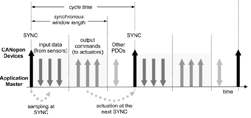
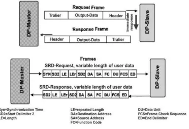
(34) The following diagram shows the frame format of a CAN/DeviceNet frame:. Figure 3: DeviceNet frame (SMAR Industrial Automation, 2001). It can be seen that for up to 8 bytes of data the overhead of a DeviceNet frame is only 36 bits (4.5 bytes), this overhead can be seen as even less when counting the function codes in the 11 bit identifier. If more than 8 bytes of data need to be transmitted over a DeviceNet network, the data will need to be fragmented; this will further increase overhead, and may reduce the number of bytes per data frame if they need to be used for data such as fragment count. (Reynders, Mackay, & Wright, 2005) An additional benefit of using DeviceNet is that TCS has a lot of experience using DeviceNet due to the fact that it has already developed various DeviceNet products. These DeviceNet ready products may even be able to be integrated into the PCC system. CANOpen In CANOpen, a frame of data is referred to as an object. The following is a list of the various types of objects and what they are used for: . Process data object (PDO): These objects are used for real-time communications such as sensor inputs and actuator outputs. Service data object (SDO): These objects are used for non-real-time communications such as setting parameters in devices and carrying out diagnostics. Emergency object (EMCY): These objects are used to notify the control application of errors and alarm events. Synchronisation object (SYNC): These objects are used to achieve synchronised and coordinated operations in the system.. Even though CAN networks can support multi-master communications, CANOpen is a master-slave protocol with only one master application controlling the network.. 33.
(35) The following diagram shows how a CANOpen network is controlled by the master to ensure a reliable network update time:. Figure 4: CANOpen synchronous operation (Cena & Valenzano, 2005). To ensure synchronisation is carried out correctly, an appropriate cycle time needs to be set; in CANOpen this is a set value in the master controller. CANOpen therefore isn’t as adaptable to plug and play as DeviceNet. (Cena & Valenzano, 2005) FlexRay based protocols FlexRay is currently only being used in the automotive industry, this industry is very competitive and does not release any information on their communications protocols. FlexRay is very similar to CAN so the communications protocols that would be used on a FlexRay bus will be very similar to those used on a CAN bus (mentioned above), only with less overhead due to the larger data allocation in a FlexRay frame. EIA485/SPI based protocols EIA-485 is very commonly used in industrial communications applications. There are various communications protocols used in EIA-485 networks, these protocols vary from manufacturer to manufacturer and a few have been developed into industrial standards. Modbus and Profibus are two of the most common communications protocols used with EIA-485 networks. It could also be possible to develop a custom communications protocol for use on the EIA-485 data bus.. 34.
(36) Modbus The Modbus protocol was originally developed by American PLC manufacturers, but is now a worldwide standard. A lot of European PLCs are compatible with Modbus, but it is still most common in American PLCs. The diagram below shows how the Modbus application layer can be applied to various physical layers:. Figure 5: Modbus applications (Reynders, Mackay, & Wright, 2005). When applied to an EIA-485 Network, Modbus operates in a Master-Slave format where the initiator (client) will send a request for data, which is responded to by the server with the data; this can be seen in the following diagram:. Figure 6: Modbus transaction (Reynders, Mackay, & Wright, 2005). The following diagram shows the structure of the Modbus protocol:. Figure 7: Format of Modbus message frame (Reynders, Mackay, & Wright, 2005). The first byte represents the address field, although practical limitations allow only a limited number of devices, each slave can have an address between 1 and 247. In a request message the address field is used to identify the device to which this request is being sent and in a response message this field is used to identify the device that has sent the response.. 35.
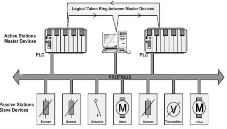
(37) The second byte represents the function to which the message is related, this byte remains the same for a request and response message. A few examples of Modbus function codes are: . 01: Read coil status 05: Force single coil 07: Read exception status Etc…. The data field is variable length. In a request frame the data field contains whatever information the PLC needs to complete the requested function. In a response frame the field contains any data requested by the host. The last two bytes comprise the error check field. Every message is checked for errors by performing a 16bit cyclic redundancy check (CRC) on the message frame; this assures that devices do not react to corrupted messages. (Reynders, Mackay, & Wright, 2005) The total overhead of a Modbus message is therefore 4 bytes, this does not include the overhead caused by the fact that each message has to be preceded by a request or followed by a response. Profibus The Profibus protocol was originally developed by European PLC manufacturers, but is now a worldwide standard. A lot of American PLCs are compatible with Profibus, but it is still most common in European PLCs. There are various versions of Profibus: . Profibus DP (distributed peripheral): this protocol has only one master and multiple slaves. Profibus FMS (fieldbus message specification): this protocol has multiple masters that communicate peer to peer. Profibus DP/FMS COMBI: some Profibus devices support having multiple masters and multiple slaves on the same network. Profibus PA: this protocol is intrinsically safe.. A Profibus master is a controller of some form (this can range from PLC to smart sensor). Profibus master devices have the right to transfer messages without any remote request. A Profibus slave is a peripheral device such as a transmitter or a sensor, these devices may only acknowledge received messages.. 36.
(38) When set up as a multiple master system (Profibus FMS) Profibus operates a token passing system, where the master can only transmit data when it has the token, this prevents collisions on the bus. When set up as a master-slave system (Profibus DP) slave devices are polled by the master at regular intervals. These two methods can be combined into a hybrid system (COMBI) where the master holding the token polls the slaves then passes the token on etc… the following diagram shows this setup:. Figure 8: Profibus COMBI setup (Reynders, Mackay, & Wright, 2005). 37.
(39) The following diagrams show the frame formats used by Profibus:. Figure 9: User data exchange for Profibus DP (Reynders, Mackay, & Wright, 2005). It can be seen that Profibus has a similar frame structure to Modbus (see the top part of the above figure). (Reynders, Mackay, & Wright, 2005). SPI based protocols During further investigation into EIA485 it was decided that SPI did not have any attributes that made it significantly better than EIA485 to warrant any further investigation.. 38.
(40) Comparison between protocols Due to lack of information on FlexRay and the elimination of SPI it was decided to limit further investigations to CAN and EIA485. The following comparison was set up with information gained by research and some help from TCS staff. It compares various features relevant to the requirements set by TCS that the backplane would have if it used a CAN bus with a custom protocol based on CANOpen and DeviceNet or an EIA485 bus with a custom protocol based on Modbus and Profibus.. Recommended protocol Data Rate FIFO Buffers Number of devices Communication Model. Data. Overhead (Electrical) Overhead (Processor). Actual data rate after overhead Error checking. CAN Custom based on: CANOpen/DeviceNet. EIA485 Custom based on: Modbus/Profibus. 1Mbps yes. 2Mbps (depending on whether the controller can handle it) no 32. 127 Master-Slave, Client-Server or Producer-Consumer CANOpen has a 4 bit part for data length, with 8 bytes per frame => total length is 128 bytes. 44 bits per frame of 108 bits (always 40%) No need to implement software FIFO. 600Kbps Link layer built in with CSMA/NDBA, ACK etc…. Master-Slave only. N*8 bytes up to 252 bytes 60% for small amounts of data such as digital I/O but it can get up to as low as 20% for large amounts of data such as Ethernet Need to implement software FIFO 400Kbps for small frames such as digital I/O to 800Kbps for large frames such as Ethernet. Maybe less depending on processor load due to processor overhead Need to set up link layer in the CPU. The values for overhead are rough estimations based on the frame structure of CAN and Modbus frames, this does not take into consideration that Modbus operates on a polled/token ring passing system because a custom version of the protocol might not use any of those systems. Removing doubt that CAN isn’t appropriate During research there were some doubts that CAN was not an appropriate protocol for transferring Ethernet frames because of the size of Ethernet frames and the fact that most Ethernet networks run at speeds of 10 mbps to 1 gbps which is much faster than the speed at which a CAN bus is able to transmit data. This section discusses why this limitation was acceptable: It was decided that the main controller of the PCC was to have an on-board Ethernet port capable of speeds of up to 100 mbps. The main port would be enough to connect the controller to the main factory network. Any additional ports were to be specified for use as a local low speed subnet or to attach devices such as network printers which only require transmission of low data volumes at long intervals. 39.
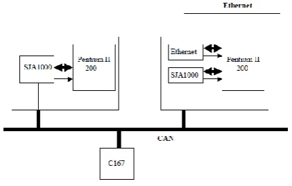
(41) A research paper was found called “Porting the Internet Protocol to the Controller Area Network” by Ditze et. al. The main object of their research carried out by Ditze et. al. was to see if they could stream video to the internet from devices on a CAN network. The following figure shows the setup they used:. Figure 10: IP over CAN Hardware Architecture (Ditze, Bernhardi, Kamper, & Altenbend, 2003). Because Ethernet packets can be up to 1500 bytes long, the packets needed to be fragmented into 7 byte fragments with the remaining data byte of the CAN frame used for sequencing numbers. The test setup used consisted of two PCs with SJA1000 CAN controllers and a Microcontroller with a CAN controller (C167). One of the PCs was connected to the Internet via an Ethernet network. The most significant test carried out was a video streaming test where video was streamed from the PC without Internet connection to the Internet via the PC with the Ethernet connection all whilst the C167 was also transmitting data. By carrying out this test Ditze et. al. proved that low quality streams of around 380 kbps could be handled over a CAN network. (Ditze, Bernhardi, Kamper, & Altenbend, 2003) This research gave a good indication of the speeds that could be expected from porting Ethernet over a CAN backplane, these speeds were deemed more than acceptable in terms of the requirements for speed of the Ethernet modules by TCS staff.. 40.
(42) 3.7. Recommendations. Below are a few recommendations for any further research that could be carried out into backplane options for the PCC: . Look into the electrical layer/specifications of higher speed protocols such as USB and FireWire to see if there is potential to run a protocol allowing a bus topology on it. Carry out further investigations into FlexRay. At the time of this research it was still quite rare, but in the future components might become more common. Because FlexRay was only removed as an option due to lack of availability it might become a viable option when components are more readily available.. As with FlexRay, an optical bus may also become viable if components become more widely available. It is highly unlikely that an optical bus can be laid out in a bus topology, but the extremely high speeds and immunity to electrical noise could supersede the need for it to be in a bus topology. When not using a bus topology, it is important to take care that the nodes in the network still aren’t reliant on each other in a way that if one module fails, the rest of the bus doesn’t go down (There is no single point of failure). This is a serious factor that will need to be considered when selecting a bus option such as an optical bus.. 41.
(43) 3.8. Discussion. Overall the research went quite well. Due to loose selection criteria and time restrictions, there were an almost overwhelming amount of options. This limited the depth of investigation into the lesser known bus types. Because some backplane options couldn’t be investigated too deeply, there may have been a bias towards more familiar backplane options. If more time was spent looking into certain bus types or protocols, it may have come out that there were specific features making them ideal for use as a backplane that weren’t immediately apparent. It could be seen as a good thing that a familiar bus type was picked because it allows more time for software and protocol development or less overall development time allowing TCS to determine whether the PCC is a viable product before investing large amounts into researching better backplane options.. 42.
Figure
+7
Related documents
We apply the framework developed in Reitz and Taylor (2008) to daily data on the yen-US dollar exchange rate and on Federal Reserve and Japanese Ministry of Finance
Formally as it was shown above that prohibition does not exist even in standard quantum mechanics (there is no laws of conversation for single processes with small
The present study was carried out to determine the physico-chemical properties and heavy metal content of the cassava mill effluent, to compare soil physico-chemical properties
Materials and Methods: The specificity of the assay was tested using reference strains of vancomycin-resistant and susceptible enterococci.. In total, 193
4b (again, vehicle icons are not drawn to scale). This area was approximately 2. We analyzed scenarios with different vehicle densities per square kilometer, as specified in Table
This study proposed a systematic grounded theory approach to discover if students became motivated for reading by being given an opportunity to select reading content for
The aim of this study is to describe the meaning of hospice nurses ’ lived experience with alleviating dying patients’ spiritual and existential suffering.. Methods: This is
