and Plate Rheometer
Vincent Cregan, Stephen B.G. O’Brien, and Sean McKee
Abstract A cone and a plate rheometer is a laboratory apparatus used to measure the viscosity and other related parameters of a non-Newtonian liquid subject to an applied force. A small drop, of order millimetres, of the liquid is located between the horizontal plate and the shallow cone of the rheometer. Rotation of the cone ensues, the liquid begins to flow and the plate starts to rotate. Liquid parameters are inferred based on the difference in the applied rotational force and the resulting rotational force of the plate. To describe the flow of the drop, the initial drop configuration, before rotation commences, must be determined. The equilibrium drop profile is given by the solution to the well-known nonlinear Young–Laplace equation. We formulate asymptotic solutions for the drop profile based on the small Bond number. The modelling of the drop exhibits a rich asymptotic structure consisting of five distinct scalings which are resolved via the method matched asymptotics.
1
Introduction
The study of surface tension and capillarity has long been an area of interest to both scientists and applied mathematicians. The importance of capillarity phenomena is highlighted by their abundance in both nature (self-cleaning behaviour of the lotus plant [1] and the water repellent properties of water striders [3]) and industry (glass fabrication [4] and in the application of coatings to surfaces such as television screens [7]).
V. Cregan ()S.B.G. O’Brien
MACSI, University of Limerick, Limerick, Ireland e-mail:[email protected];[email protected]
S. McKee
University of Strathclyde, Glasgow, Scotland, UK e-mail:[email protected]
M. G¨unther et al. (eds.), Progress in Industrial Mathematics at ECMI 2010, Mathematics in Industry 17, DOI 10.1007/978-3-642-25100-9 51, © Springer-Verlag Berlin Heidelberg 2012
Early attempts at understanding surface tension include Leonardo da Vinci’s ad-hoc, intuitive explanation for capillary effects and Newton’s experiments involv-ing the rise of a liquid up a thin tube based on the attraction of the liquid to the tube [8]. In the early nineteenth century, the independent surface tension research of Young and Laplace resulted in the Young–Laplace capillary equation
p D
1
R1 C 1 R2
; (1)
which describes the equilibrium profile of a static liquid–gas interface. We observe thatpis the pressure difference across the liquid interface,is the surface tension andR1andR2are the principal radii of curvature.
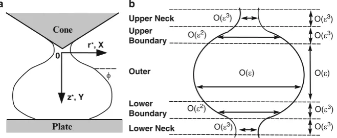
A cone and plate rheometer is a laboratory device used to study the way in which a non-Newtonian fluid flows and deforms subject to an applied force. A fluid drop is placed on the flat plate of the rheometer and the shallow cone is lowered towards and in to the drop (see Fig.1a). Typically, the plate is rotated though in certain designs the cone may rotate. The rotational force causes the fluid to flow and thus, cone rotation ensues. On the basis of the difference of the applied force and the resulting rotational force exerted on the cone, parameters such as fluid viscosity can be established. To simulate the fluid flow associated with the drop in contact with the cone and plate rheometer the initial, static drop profile must be determined.
The method of matched asymptotics is used to derive expressions for the shape of the static drop profile. The perturbation approach is based on the small Bond number—where surface tension dominates body force terms—and is similar to previous work on sessile drops and pendant drops [5].
Plate Cone
r*, X
z*, Y 0
a
φ
Upper Neck
b
Lower Neck Upper Boundary
Lower Boundary Outer
O(ε3) O(ε2)
O(ε2)
O(ε3) O(ε3)
O(ε3)
O(ε3)
O(ε3)
O(ε) O(ε)
[image:2.439.57.387.384.519.2]2
Mathematical Model and Nondimensionalisation
Assuming that the contact angles are constant, the resulting drop is axisymmetric with profile z D z.r/with respect to a polar coordinate system aligned such that z D 0is located at the thinnest part of the upper neck of the drop with the z-axis pointing downwards in the direction of gravity (see Fig.1a). The hydrostatic pressure in the drop is given bypCgzwhereis the fluid density,gis gravity andpis the unknown pressure at zD0where the profile becomes vertical. Thus, at the liquid–gas interface, the hydrostatic pressure in the drop is balanced by the capillary forces and it follows from (1) that
z00
. 1 C z02/3=2 C
z0 r. 1C z02/1=2
D pC gz; (2)
where differential geometry has been used to formulate expressions forR1andR2. We adopt the standard nondimensionalisation approach [5] and we nondimen-sionalise (2) via the fundamental dimensionless variables
z D aY; r D aX; p D gaP; (3)
whereap=.g/is the liquid capillary length, to obtain
Y00
. 1C Y02/3=2 C
Y0
X . 1 C Y02/1=2 D P C Y: (4)
From a numerical perspective a more convenient parametric formulation of (4) is
dX
ds D cos ;
dY
ds D sin ;
d ds C
sin
X D P C Y; (5)
whereis the inclination (see Fig.1a) andsis the arclength. Finally, elimination of the arclength from (5) yields
dX d D
X cos XP CXY sin;
dY d D
X sin
XP CXY sin; (6)
which is the starting point for our asymptotic analysis.
We denoteLto be the maximum radius of the drop (or drop half-width) in the main body of the drop where its profile becomes vertical [9]. From previous work [5], we assume that the width of the neck isO."3/where"L=apL2g=is the dimensionless half-width and may also viewed as a Bond number. We consider solutions for"1(orLa) which represents the dominance of surface tension over body force effects in determining the drop profile.
X.D=2/D˛"3andY.D =2/D0where˛is anO.1/parameter which is found via the asymptotic analysis. The dimensionless half-width conditionX. D =2/D"fixes the pressureP. In relation to the contact angles we adopt the strategy of previous authors whereby the contact angles are used to determine the points at which the drop is in contact with the cone and the plate [5]. For example if the lower contact angle is=2we truncate the solutions at the point in the main body of the drop where the profile becomes vertical.
The drop asymptotic structure consists of an upper neck, an upper boundary layer, an outer region (main body), a lower boundary layer and a lower neck (see Fig.1b) and is based on previous work on sessile drops and pendant drops [5,6,8].
3
Results
To reflect the balance between the surface tension curvature terms, which are opposite in sign, in the upper neck of the drop we define the rescaled neck variables
X D "3
u; Y D "3v ; P D p=" ; D O.1/; (7)
which upon substituting into (6) leads to the leading order equations
du
d D u cot ;
dv
d D u; (8)
with boundary conditions u.D=2/D˛andv.D=2/D0. The correspond-ing solutions are
u D ˛csc ; v D ˛lnjtan=2j; (9)
where we note the existence of a singularity as!0which implies that the upper rescaling is not appropriate and an alternative set of scaled variables must be defined. The upper boundary layer provides a transitional layer between the curvature dominated terms of the upper neck region and the three term balance in the main body of the drop. Moreover, Fig.1b illustrates a change in sign in the curvature in the upper boundary layer which suggests the presence of a point of inflection. Consequently, (6) is rescaled via
X D "2 ; Y D "3 ; P D p=" ; D "˚; (10)
to obtain the leading equations
d d˚ D
p ˚ ;
d d˚ D
˚
We note the solution
D 12
(
˚ ˙ p˚2 C 4C)
; (12)where the positive root applies before the point of inflection, located at D "p4C, and the negative root applies after inflection. The unknown integration constants are found via asymptotic matching [2].
In the main body of the drop, the basic shape is nearly spherical and the fundamental balance is between the curvature terms and the pressure term P. To highlight this balance we rescale (6) by the outer variables
zDLx; rDLy; (13)
to attain the outer equations
dx d D
xcos "2xy C xp sin;
dy d D
xsin
"2xy C xp sin; (14)
with the conditionx. D =2/D 1. The presence of the"2terms in (14) suggest O."2/asymptotic expansions inx,yandp. The leading order solutions are
x0 D sin ; y0 D 1 cos ; p0 D 2; (15)
which represents a circular drop profile. Proceeding toO."2/we have
x1 D 16 .13˛/cos2 2cos
3 C 1 3˛
sin ; (16)
which upon inspection reveals a singularity as ! and thus an alternative rescaling fornearDis required.
At the base of the drop we encounter a lower boundary layer analogous to the upper boundary layer and we rescale via
X D "2 ; Y D 2"C "3 ; P D p=" ; D "˚; (17)
which upon introduction into (6) leads to a system of equations identical to (11). Noteworthy is the solution
˚ D D ; (18)
leading order and obtain the relevant solutions. The theoretical results pertaining to the lower boundary layer (˛ > 2=3) and the presence of another drop structure need to be validated experimentally.
In reality, the static solutions outlined here may be quite difficult to achieve if the appropriate experimental configuration is not calibrated correctly. Other authors have reported on systems which exhibit a similar type of multiple drop structure as outlined here [8].
0 a
1
2
3
x 10−3
0 0.002 0.004 0.006 0.008 0.01
Y
X
Upper Composite Numerical
0.05 b
0.1
0.15
0.2
0 0.02 0.04 0.06 0.08 0.1
Y
[image:6.439.55.387.172.304.2]X Outer Numerical
Fig. 2 Comparison of numerical solution (arclength formulation (5)) with associated asymptotic solutions in (a) upper neck and (b) outer region."D0:1,˛D1
0.19
0.195
0.2
0.205
0.21
0 0.01 0.02 0.03 0.04 0.05
X Numerical
Outer Neck
Lower Boundary Layer
[image:6.439.105.333.348.526.2]4
Conclusion
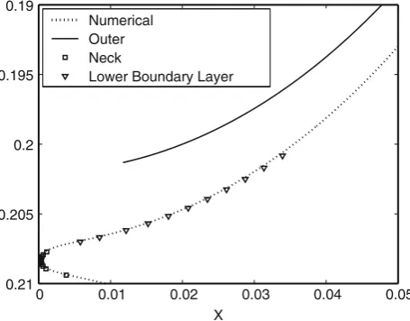
The method of matched asymptotic expansions has been used to derive asymptotic solutions for the profile of a liquid drop in contact with a cone and plate rheometer. A number of rescalings and boundary layers were required to fully describe the drop profile. As indicated by Fig.2and Fig.3the asymptotic solutions display excellent agreement with the corresponding numerical solutions.
Acknowledgements We gratefully acknowledge the financial support of the Mathematics Appli-cations Consortium for Science and Industry (MACSI) supported by a Science Foundation Ireland mathematics grant 06/MI/005 and an Embark Initiative postgraduate award RS/2006/41.
References
1. Dupuis, A., Yeomans, Y.: Modeling droplets on superhydrophobic surfaces: equilibrium states and transitions. Langmuir 21(6), 2264–2629 (2005)
2. Dyke, M.V.: Perturbation Methods in Fluid Mechanics. Academic Press, New York (Annotated edition from Parabolic Press, Stanford) (1975)
3. Hu, D., Bush, J.: The hydrodynamics of water-walking arthropods. J. Fluid Mech. 644, 5–33 (2010)
4. Nemchimsky, V.: Size and shape of the liquid droplet at the molten tip of an arc electrode. J. Appl. Phys. 27(7), 1433–1442 (1994)
5. O’Brien, S.: On the shape of small sessile and pendant drops by singular perturbation techniques. J. Fluid Mech. 233, 519–537 (1991)
6. O’Brien, S.: Asymptotic solutions for double pendant and extended sessile drops. Q. Appl. Math. 52(1), 43–48 (1994)
7. O’Brien, S.: The meniscus near a small sphere and its relationship to line pinning of contact lines. J. Colloid Interface Sci. 183(1), 51–56 (1996)
8. O’Brien, S.: Asymptotics of a sequence of pendant drops. SIAM J. Appl. Math. 62(5), 1569– 1580 (2002)