A comparison between single sided and double sided friction stir welded 8mm
thick DH36 steel plate
N.A. McPherson
BAE Systems Marine - Naval Ships, Glasgow, G51 4XP, Scotland, UK norrie.mcpherson@baesystems.com
A. M. Galloway
Strathclyde University, Glasgow, United Kingdom alex.galloway@strath.ac.uk
S. R. Cater
TWI Technology Centre, Yorkshire, United Kingdom stephen.cater@twi.co.uk
M. M. Osman
Military Technical College, Cairo, Egypt m.mahmoud@lycos.com
Abstract
As part of an ongoing process to fully evaluate the potential for friction stir welding (FSW) to be used in the shipbuilding industry, a comparison has been made between two variants of the process. 8mm thick DH36 steel plate was friction stir welded using a single sided and a double sided process. An assessment of the processes was made to report on the resultant distortion behaviour, hardness, yield strength, toughness and microstructure. As a further comparison, additional work on 8mm thick submerged arc welded (SAW) DH36 plate has been included as the current shipbuilding benchmark. The overall process feasibility will be assessed including the issue of the requirement to rotate the workpiece through 180° to complete the second side of the double sided process.
Keywords
Friction Stir Welding (FSW), DH36, Plate distortion, Weld toughness, Submerged Arc Welding (SAW).
Introduction
Many industries, especially transportation (railways, automotive, shipbuilding and aerospace), are considered to be major investors in advanced welding research because of the direct impact of the research outcomes on their product quality and versatility. In recent years, this investment has promoted the development of more advanced welding techniques than the commonly used arc welding processes. The prerequisites necessary for commercializing these continually developing
(mm sec-1)] of 1.72 rev/mm. These FSW parameters developed a microstructure with a combination of bainite and martensite in the nugget region whereas it was pearlite and martensite in the HAZ region. Regions of martensite showed a maximum hardness of 415 HV0.3 (using indentation load of 300 gf) whereas the parent material showed a value of 177 HV0.3. Lienert et al. [9], studied the same process parameters on the same material but with a W-25%Re tool having the same geometry as that used in the study by Reynolds et al. [8]. However, a welding speed of 200 mm/min and 2 rev/mm weld pitch was used. A maximum hardness of 215 HV0.5 (using indentation load of 500 gf) was measured in the nugget region that showed no evidence of martensite. All the previously presented observations have been carried out on steel plates with thicknesses less than 6 mm. FSW of thicker plates requires stir tools with longer pins manufactured from stronger tool materials and recent developments in modern tool materials has looked primarily at refractory metals (W-Re), polycrystalline boron nitride (PCBN) and WC. Another way to successfully weld greater thicknesses of carbon steel plate involves passing the tool along both sides of the abutted plates in sequence [10], hence the term double sided FSW. However, FSW involves complex interactions between a variety of simultaneous thermomechanical processes and these interactions affect the heating and cooling rates, plastic deformation and flow, dynamic recrystallization and mechanical integrity of the joint [11]. The objective of the present study is to evaluate and compare the extent of post weld distortion, microstructure, hardness and toughness of the micro-alloyed 8mm plate DH36 steel plates subjected to single and double friction stir welding regimes. Comparisons will also be drawn against the benchmark process, namely SAW.
Experimental Work
Material Used
The as received DH36 micro-alloyed steel was supplied in the form of rolled plates with dimensions 2000 x 300 x 8mm (length x width x thickness). The plate chemical composition given by the supplier fitted well with the actual chemical analysis, which was carried out using optical emission spectroscopy. This is shown in Table (1) and the carbon equivalent for the shown chemical composition is 0.37% as calculated from the Dearden and O'Neill formula was adopted in 1967 [12].
15 5
6
Ni) %(Cu V) Mo %(Cr %Mn %C
[image:2.595.320.551.306.414.2]CE= + + + + + +
Table 1: Chemical analysis for the as received 8 mm DH36 steel (wt%)
C 0.14 S 0.008
Si 0.37 Al 0.01
Mn 1.34 Nb 0.03
P 0.017 N 0.003
Fe Rem.
Welding Procedures
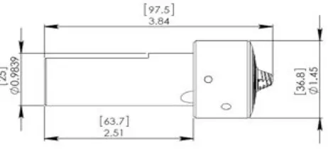
The as received DH36 steel plates were initially checked for edge straightness and profile. They were tightly clamped to the table of TWI’s Power Stir computer controlled friction stir welding machine. For good contact and homogenous distribution of the forces exerted by the tool shoulder, the surface of the side to be welded was milled smoothly for about 30mm with a very high rotating shank milling tool to remove the paint primer from the weld area. The single sided FSW process was performed in the counter clock wise (CCW) direction using the MegaStir tool shown in Fig. 1 with a pin length of 8 mm and a shoulder of 36.8mm. Performing the double sided FSW, similar tools but with 4mm and 6mm pin lengths were used respectively. All the tool pins were made from polycrystalline boron nitride (PCBN) Q70 material, whereas the rest of the tool was made from a refractory metal alloy.
Fig. 1: Friction stir welding tool geometry
[image:2.595.370.497.534.628.2]To apply the second pass of the FSW, the plates were rotated around their welding axes after completing the first weld. All welding passes were performed with a welding traverse speed of 125 mm/min, rotation speed of 250 rev/min (a weld pitch of 2 rev/mm) and an axial force of 60 KN in the Z direction. For comparison purposes, two additional DH36 plates with the same thickness were welded together using the (SAW) process in two passes as shown in Fig. 2.
Fig. 2: SAW Passes
Distortion Measurement
centered and leveled above these four screws and a complete laser scan for the plate top surface was carried out. This scan was applied using a laser probe supported in a moving carriage in a plane parallel to the leveling plane with a separation distance of 30 cm. This probe allows the determination the height difference of the plate surface with respect to the leveling plane (30 cm – plate thickness in (cm)) in steps of 20 mm in both X and Y directions. The data was captured and processed by the Lab View software package where the plate surface profile shows the plate distortion.
Microstructure Evaluation
The microstructure of the as received plates as well as that for the single and double sided friction stir welds was optically investigated using an Olympus GX-51 metallurgical microscope. In addition, a scanning electron microscope (HITACHI S-3700), with a large chamber (150 x 110 mm), was used for higher magnification and spot analysis. This scanning microscope was equipped with the Energy Dispersive Spectroscopy (EDS) capability, Oxford Inca 350 with 80 mm X-Max detector that allows precise elemental analysis. All the microstructure investigations were conducted in a plane perpendicular to the weld passes.
[image:3.595.324.542.131.239.2]Mechanical Testing
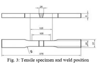
Fig. 3: Tensile specimen and weld position
Tensile test specimens were machined according to the British Standard (BN EN ISO 4136:2011) in directions perpendicular to the centre line of the weld so that the weld region is exactly in the mid of the original length as shown in Fig. 3. These specimens were used to evaluate the mechanical properties of the as received plates as well as to compare its strength with that of the weld region. Toughness of the weld joint in different zones was evaluated by using the standard V-notch Charpy specimen according to the British Standard (BS EN ISO 148-1:2010) but with a height equal to the plate thickness (8mm). The specimens were machined in a direction perpendicular to the weld centre line so that the vertex of the notch is in position (-6, -4, -2, 0, +2, +4, +6) mm from the centre line as shown in Fig. 4. At each position, three impact specimens were machined and tested at -20○C. Hardness maps
for the weld joint, were produced using fully automated microhardness tester equipment with a 1kg load.
Using a motorized stage, measurements were carried out in steps of 0.7 mm in both X and Y direction, following the
[image:3.595.66.259.394.521.2]programmed regime. Indentations were adjusted in parallel rows with 0.5 mm away from the plate surfaces.
Fig. 4: Charpy impact test orientation and notch position with respect to the weld centreline
Results and Discussion
Hardness
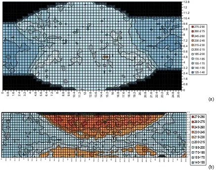
The hardness scans for the SAW and double sided FSW weld regions are shown in Fig. 5. Overall the FSW weld metal is slightly harder than the SAW, but it is not at a level that would cause any concern. However in the FSW representation there is an area in the overlap region which has been softened, and this may have an effect on the mechanical properties.
Plate Distortion
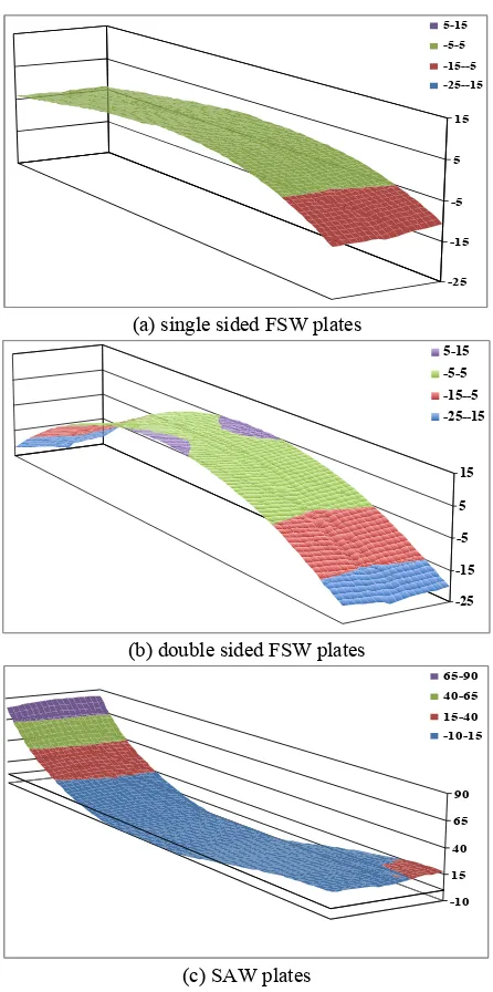
Both surfaces of the single and double sided friction stir welded FSW plates were scanned for distortion. Depending on the bending direction (top/down), the surfaces show different profiles. These profiles that show maximum deviation from the leveling plane are shown in Fig. 6. For comparison, the distortion profile for the arc welded plates is shown in the same figure. All plates show a longitudinal distortion along the Y axis but with different degrees of deformation. In the single sided FSW plates, a range of (5 to -5 mm) deviation from the leveling plane covers most of the plate length whereas the rest lies in the range of (-5 to -15 mm). The same distortion behavior is observed for the double sided FSW plates but with wider range (5 to -25 mm). The arc welded plates profile shows asymmetric distortion behavior rather than the symmetrical behavior shown for the FSW plates, where most of the distortion is clearly observed in the edge of the plates in the range (15 to 90 mm). Significant angular distortion around the Y axis is observed for the arc welded plates, whereas very little is observed in the FSW plates.
Microstructure evaluation
Microstructure variation of the weld joint for the 8mm single sided FSW plate is shown in Fig. 6. Explaining this variation, one should clearly understand the effect of many interacting phenomena that take place as a consequence of the stirring operation. During FSW, the tool is forced axially in the Z
Notch end (2mm from the plate surface)
Notch position from the weld C.L.
L
T
-6 mm -4 mm -2 mmWeld C.L.
Notch end (2mm from the plate surface)
Notch position from the weld C.L.
L
T
-6 mm -4 mm -2 mmWeld C.L.
Notch end (2mm from the plate surface)
Notch position from the weld C.L.
L
T
-6 mm -4 mm -2 mmWeld C.L.
Notch end (2mm from the plate surface)
Notch position from the weld C.L.
L
T
L
T
-6 mm -4 mm -2 mm(a)
[image:4.595.84.521.100.443.2](b) Fig. 5: Hardness scans of 8 mm (a) SAW and (b) double sided FSW
direction to keep its shoulder in direct contact with the plate surface, continuously rotating and heating the material. Some authors [13], have reported that the material temperature beneath the tool shoulder is constantly in the range of 1000 -1200○C, depending on the welding parameters. These authors
[13, 14] proved either experimentally and/or analytically that the friction of the tool shoulder produces most of the heat generated during the FSW process whereas the tool pin participation is comparably low. In spite of this fact, they presented temperature profiles showing that the material adjacent to the tool pin always has a higher temperature. On the contrary, they related the metallurgical development (mainly dynamic recrystallization phenomena observed in the nugget) during the FSW process to the mechanical action exerted by the tool pin together with the generated heat flux. However, Fig. 7 (a) shows the macrostructure of the single sided FSW joint. In this macrostructure, the weld region is surrounded by the thermo mechanically affected zone (TMAZ). The parent material shown in Fig. 7 (b) shows a banded ferrite and pearlite microstructure. . In the boundary of the TMAZ, the pearlite has been seen to start to degenerate and will probably be a mixture of various transformation products, shown in Fig. 7 (c). Going towards the weld region, receiving more deformation during the FSW process by the tool pin, enhances the dynamic recrystallization process
reported by [15-18] and produces finer acicular structure in combination with areas of ferrite in Fig. 7 (d). In the weld region, the welded material received maximum deformation, higher temperature and encountered a relatively lower dissipation rate that produced a relatively uniform acicular ferrite structure. Fig. 7 (e).
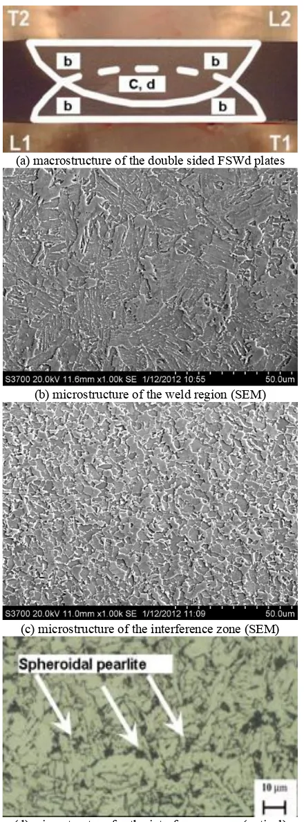
The microstructure of the double sided stir welded joint shows the same microstructure as was observed in the single sided stir welded joint except for the interference zone between the two passes as shown in Fig. 8 (a). In this zone, the microstructure observed by the SEM shows that the grains are equiaxed and smaller than these grains of the rest of the weld Fig 8(b and c). This morphology as well as the grain size is expected to raise the material toughness and enhance the relevant mechanical properties. Optically, the observed microstructure shows the presence of degenerated pearlite, on the ferrite boundaries. Further higher resolution work is required in this area to more fully understand the phases present in the overlap area.
0
0.8 1.6 2.4 3.2 4 4.8 5.6 6.4 7.2 8 8.8 9.6 10.4 11.2 12
(a) single sided FSW plates
(b) double sided FSW plates
[image:5.595.50.273.103.551.2](c) SAW plates
Fig. 6: Post weld distortion profiles (dimensions in mm)
Mechanical property evaluation
All cross weld tensile tests fractured in the parent plate illustrating the higher strength of the weld metal in the FSW and SAW welds. This was also reported by Reynolds et al [8]. Some small scale tensile testing of longitudinal samples also confirmed this. The highest strength was seen in the double sided FSW welds, and the lowest in the SAW welds. This is a reflection of the mixed coarser microstructure of the SAW material in comparison to the regular fine acicular ferrite seen in the FSW samples.
(a) macrostructure of the single sided FSWd plates
(b) parent material
(c) TMAZ near to the parent plate
(d) TMAZ near tp the weld
[image:5.595.325.542.109.702.2](e) microstructure of the weld
Fig. 7 Macro and microstructure for the single sided FSW -25
-15 -5
5 15 5-15 -5-5
-15--5 -25--15
-25 -15 -5 5 15 5-15 -5-5 -15--5 -25--15
(a) macrostructure of the double sided FSWd plates
(b) microstructure of the weld region (SEM)
(c) microstructure of the interference zone (SEM)
[image:6.595.53.273.104.698.2](d) microstructure for the interference zone (optical)
Fig. 8: Macro and microstructure for the weld region and the interference zone (double sided FSWd joint)
[image:6.595.323.546.211.332.2]The toughness of the three welds is shown in Fig. 9 and this data is based on a Charpy specimen size of 10 x 7.5 mm. based on this data it would appear that the double sided FSW process has the potential to improve the weld toughness over the single sided FSW and SAW. This will be related to the relative microstructures, such as the softer area in the overlap, but that requires more research.
Fig. 9: Absorbed energy along the weld joint
Conclusions
1) Single/double sided friction stir welding produces lower angular and longitudinal distortion than the sub arc welding of DH36 shipbuilding steel.
2) Strength and hardness of the double sided friction stir welded joint are higher than that of the single sided friction stir welded joint.
3) Performing the second pass in the double side friction stir welding process creates an improvement in toughness which is likely to be related to microstructural differences.
4) There is scope for further work based on this study on the exact contribution to the effects in the overlap area on the overall properties
Acknowledgements
The authors would like to acknowledge the tireless help of the technical team in TWI in performing the FSW and Stuart Campbell (AMRL) in Strathclyde University in helping measuring the plates distortion. BAE Systems-Marine is acknowledged for supplying the material and funding the experimental work.
References
[1] Pace, D. P., Kenney, K. L., and Galiher, D. L., “Laser assisted arc welding of ultra high strength steels,” Proc 6th- Trends in Welding Research, Pine Mountain, GA, 2002, pp. 442–447.
0 25 50 75 100 125 150
-6 -4 -2 0 2 4 6
Position from the weld center (mm)
A
bs
orbe
d
E
ne
rgy
[
J/-20
○
C
]
[2] McPherson, N. A., “Thin plate distortion reduction—a management or technology issue?” Welding and Cutting, No. 5 (2006), pp. 277–282.
[3] Roland, F., Manzon, L., Kujala, P., Brede, M., and Weitzenböck, J., “Advanced joining techniques in European Shipbuilding”, Journal of Ship Production, Vol. 20, No. 3 (2004), pp. 200–210.
[4] Sa´nchez-Amaya, J. M., Delgado, T., Gonza´ lez Rovira, L., Botana, F.J., “Laser welding of aluminium alloys 5083 and 6082 under conduction regime”, Applied Surface Science, No. 255 (2009), pp. 9512–9521.
[5] Park, S. H. C., Sato, Y. S., Kokawa, H.;. 161. “Effect of micro-texture on fracture location in friction stir weld of Mg alloy AZ61 during tensile test”, Scripta Materialia, Vol. 49. No 2 (2003), pp. 161-166.
[6] Thomas, W. M., Nicholas, E. D., “Friction stir welding for the transportation industries,” Mater Des, No 18 (1997), pp. 269–273.
[7] Thomas, W.M., Nicholas, E.D., Needham, J.C., Murch, M.G., Dawes, C.J., “Friction stir butt welding,” International Patent, PCT/GB92/02203; 1991.
[8] Reynolds, A. P., Tang, W., Posada, M. and DeLoach, J., “Friction stir welding of DH36 steel”, Science and Technology of Welding and Joining, Vol. 8, No. 6 (2003), pp.455-461.
[9] Lienert, T.J., Tang, W., Hogeboom, J.A., and Kvidahl, L.G.’’ Friction stir welding of DH36 steel’’ Proceedings of 4th International Symposium on Friction Stir Welding, May 14-16, 2003, Park City, UT
[10]Barnes, S. J, Steuwer, A., Mahawish, S., Johnson, R., Withers, P. J., “Residual strains and microstructure development in single and sequential double sided friction stir welds in RQT-701 steel”. Materials Science and
Engineering A, Vol. 492 (2008), pp 35-44.
[11]Su, J. Q., Nelson, T.W., Mishra, R. , Mahoney, M., “Microstructural investigation of friction stir welded 7050-T651 aluminium”, Acta Materialia, Vol. 51, No. 3 (2003), pp.713-729.
[12]Lancaster, J.F., Metallurgy of welding - Sixth Edition. Abington Publishing (1999). pp. 464-465.
[13]Cook, G., Nielsen, B., “An Analytical Solution to Heat Dissipation during Friction Stir Welding of Steel X65”,
JAMHT, Vol. 1, No. 1 (2007), pp. 1–13.
[14]Buffa, G., Fratini, L., Pasta, S., Shivpuri, R., “On the thermo-mechanical loads and the resultant residual stresses in friction stir processing operations”, CIRP
Annalsys Manufacturing Technology, Vol. 57 (2008), pp.
287–290.
[15]Bao, S., Zhao, G., Yu, C., Chang, Q., Ye, C., Mao X., “Recrystallization behavior of a Nb-microalloyed steel during hot compression” Applied Mathematical
Modelling, Vol. 35 (2011), pp. 3268–3275.
[16]Liang-yun, L., Chun-lin, Q., De-wen, Z., Xiu-hua, G., Lin-xiu, D., “Dynamic and Static Recrystallization Behavior of Low Carbon High Niobium Microalloyed Steel” Journal Of Iron And Steel Research, Vol., 18, No.1(2011), pp. 55-60.
[17]Mejía, I., Bedolla-Jacuinde, A., Maldonado, C., Cabrera J.M., “Determination of the critical conditions for the initiation of dynamic recrystallization in boron microalloyed steels” , Materials Science and Engineering A, Vol. 528 (2011), pp. 4133–4140.