Rochester Institute of Technology
RIT Scholar Works
Theses
Thesis/Dissertation Collections
5-6-2010
Providing flow parameters for approximate die
design models and the improvement and
verification of those models using cfd analysis
Mark Livelli
Follow this and additional works at:
http://scholarworks.rit.edu/theses
This Thesis is brought to you for free and open access by the Thesis/Dissertation Collections at RIT Scholar Works. It has been accepted for inclusion in Theses by an authorized administrator of RIT Scholar Works. For more information, please [email protected].
Recommended Citation
Providing Flow Parameters for Approximate
Die Design Models and the Improvement and
Verification of Those Models Using CFD
Analysis
Mark Andrew Livelli
A Thesis Submitted in Partial Fulfillment of the Requirement
for Master of Science in Mechanical Engineering
Approved by:
Dr. Steve Weinstein—Thesis Advisor
Department Head of Chemical and Biomedical Engineering
Dr. Kenneth Ruschak—Thesis Advisor
Department of Chemical Engineering
Dr. Kathleen Lamkin-Kennard
Department of Mechanical Engineering
Dr. Alan Nye
Associate Department Head of Mechanical Engineering
Department of Mechanical Engineering
Rochester Institute of Technology
Rochester, New York 14623
Permission for Duplication
Providing Flow Parameters for Approximate Die
Design Models and the Improvement and Verification
of Those Models Using CFD Analysis
I, Mark Andrew Livelli, hereby grant permission to the Wallace Memorial Library of
Rochester Institute of Technology to reproduce my thesis in the whole or part. Any
reproduction will not be for commercial use or profit.
Signature:
Abstract
The role of a coating die is to distribute a uniform, two dimensional liquid film over a solid surface, often formed as an intermediate step in the manufacturing process of polymeric sheet products. The goal of coating die design is to deliver, with a single die, the largest range of fluid rheologies and flow conditions to within specified uniformity limits. Demanding applications require the film thickness nonuniformity to be as little as one percent across the entire coating surface for acceptable quality of the final product, necessitating optimized design as well as precision manufacturing.
There are two principal techniques used for the prediction of optimal die geometry and the analysis of flow uniformity at the slot exit, which includes full numerical computation and theoretical approximate models. Three dimensional computational solutions are numerically intensive, often requiring long computational times to accurately simulate a single die flow condition, and for this reason it is difficult to optimize coating die design solely through the use of full numerical computation. In the alternative approximate modeling approach, the complete set of three dimensional equations governing flow are averaged across the cavity cross section. As a result, the details of the flow and pressure fields at each node point specified within the cavity geometry is exchanged for average flow properties. The advantage of these simplified approximate models is that they are much easier to solve, allowing for many flow conditions and geometric parameters to be tested quickly; however, quantifiable error is incurred due to the approximations of the complete three dimensional set of governing momentum equations.
necessary inputs; these parameters incorporate the specific cross sectional shape of the cavity domain into the pressure drop flow relationship.
In more complex but often superior designs, a secondary cavity and slot are added to improve flow distribution, where the function of the inner cavity and slot are identical to those respective of the single cavity coating die design, however significant flow occurs in the cross section of the outer cavity between the exit of the inner slot and entrance to the outer slot. Despite the complication of this flow in the outer cavity cross section, much of the initial work on theoretical dual cavity die design directly applied the established governing equations of flow in the inner cavity, represented in the approximate models, to both the inner and outer cavities. Ruschak and Weinstein (1997a) obtain a different outer cavity equation for the analysis of dual cavity coating dies, utilizing a perturbation technique to derive a flow equation which accounts for the three dimensional nature of the outer cavity flow and considers the nonlinearities occurring due to inertia or generalized Newtonian rheology. Here, a similar, yet generalized, shape factor for the outer cavity arises which is defined to be consistent with the usual definition for the inner cavity for purely viscous, Newtonian flow.
Dedicated to David and Susan Livelli, Jackie Livelli,
Table of Contents
Table of Contents ii
List of Figures v
List of Tables ix
Nomenclature xi
1 Die Design Fundamentals 1
2 Literature Overview 6
3 Derivation of the Outer Cavity Approximate Model 14
4 Solution of the Outer Cavity Approximate Model 24
5 Computation of the Outer Cavity Shape Factor 30
5.1 Numerical Procedure . . . 31
5.2 Mesh Generation . . . 45
5.3 Results . . . 51
5.4 Shape Factor Estimation . . . 63
5.5 Summary . . . 70
6 Validation of the Outer Cavity Approximate Model 72 6.1 Two Dimensional Validation . . . 73
6.2 Three Dimensional Validation . . . 80
6.3 Summary . . . 90
7 Design of the Outer Cavity Cross Section 91
References 124
Appendices 127
A User Defined Functions 127
A.1 Two Dimensional Velocity Inlet Profile . . . 127
A.2 Three Dimensional Velocity Inlet Profile . . . 128
A.3 Thermal Conductivity by Viscosity Duplication . . . 129
A.4 Density by Reynolds Number Duplication . . . 130
B Gambit Journal 131 C Matlab Functions 137 C.1 OuterCavityApproximation.m . . . 137
C.2 OuterCavityShapeFactor.m . . . 145
C.3 GeometryTest.m . . . 149
C.4 StandardizePlot.m . . . 152
C.5 ThreeDimensionalValidation.m . . . 157
C.6 Fluent.m . . . 161
List of Figures
1.1 Typical Single and Dual Cavity Coating Die Geometry . . . 1
1.2 Dual Cavity Coating Die Primary Flow Orientation . . . 2
1.3 Compensation Effects of Geometric Adjustments on Flow Profile . . . 3
3.1 Detailed View of the Outer Cavity Geometry Symmetric About the Inlet Plane 15 5.1 ANSYS Fluent Pressure Based Coupled Algorithm Solution Process Flowchart 42 5.2 Illustration of ANSYS Fluent Mesh Terminology . . . 44
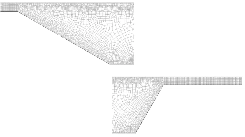
5.3 Streamlined Outer Cavity Cross Sectional Design . . . 45
5.4 Triangular 15.0-15.0 Final Mesh . . . 48
5.5 Triangular 15.0-15.0 Final Mesh Magnified . . . 48
5.6 Triangular 30.0-30.0 Final Mesh . . . 49
5.7 Triangular 30.0-30.0 Final Mesh Magnified . . . 49
5.8 Triangular 30.0-60.0 Final Mesh . . . 50
5.9 Triangular 30.0-60.0 Final Mesh Magnified . . . 50
5.10 Triangular 15.0-15.0 Outer Cavity Shape Factor First Fitted Curve Plotted Results . . . 55
5.11 Triangular 15.0-15.0 Outer Cavity Shape Factor Second Fitted Curve Plotted Results . . . 55
5.12 Triangular 15.0-15.0 Outer Cavity Shape Factor Second Fitted Curve Plotted Residuals . . . 55
5.13 Triangular 30.0-30.0 Outer Cavity Shape Factor First Fitted Curve Plotted Results . . . 58
5.14 Triangular 30.0-30.0 Outer Cavity Shape Factor Second Fitted Curve Plotted Results . . . 58
5.16 Triangular 30.0-60.0 Outer Cavity Shape Factor First Fitted Curve Plotted
Results . . . 61
5.17 Triangular 30.0-60.0 Outer Cavity Shape Factor Second Fitted Curve Plotted Results . . . 61
5.18 Triangular 30.0-60.0 Outer Cavity Shape Factor Second Fitted Curve Plotted Residuals . . . 61
5.19 Triangular 15.0-15.0 Newtonian Approximated Outer Cavity Shape Factor Plotted Results . . . 64
5.20 Triangular 15.0-15.0 Non-Newtonian Approximated Outer Cavity Shape Fac-tor Plotted Results . . . 65
n= 0.8 . . . 65
n= 0.6 . . . 65
n= 0.4 . . . 65
5.21 Triangular 30.0-30.0 Newtonian Approximated Outer Cavity Shape Factor Plotted Results . . . 66
5.22 Triangular 30.0-30.0 Non-Newtonian Approximated Outer Cavity Shape Fac-tor Plotted Results . . . 67
n= 0.8 . . . 67
n= 0.6 . . . 67
n= 0.4 . . . 67
5.23 Triangular 30.0-60.0 Newtonian Approximated Outer Cavity Shape Factor Plotted Results . . . 68
5.24 Triangular 30.0-60.0 Non-Newtonian Approximated Outer Cavity Shape Fac-tor Plotted Results . . . 69
n= 0.8 . . . 69
n= 0.6 . . . 69
n= 0.4 . . . 69
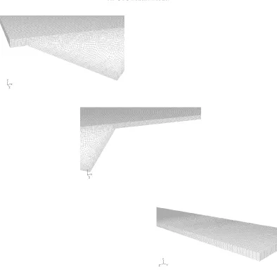
6.1 Triangular 30.0-60.0 Long Slot Final Mesh . . . 77
6.2 Triangular 30.0-60.0 Long Slot Final Mesh Magnified . . . 77
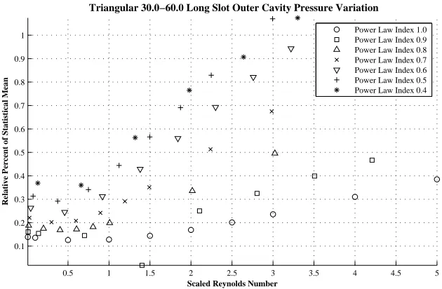
6.3 Triangular 30.0-60.0 Long Slot Outer Cavity Pressure Variation Plotted Results 79 6.4 Triangular 30.0-60.0 Three Dimensional Final Mesh Magnified . . . 86
6.5 Triangular 30.0-60.0 Three Dimensional Newtonian Inlet Flow Profile . . . . 87
6.6 Triangular 30.0-60.0 Three Dimensional Newtonian Outlet Flow Profile . . . 87
6.7 Triangular 30.0-60.0 Three Dimensional Non-Newtonian Inlet Flow Profile . . 88
7.1 Triangular 30.0-60.0 Flat Bottom 0.316 Final Mesh . . . 95
7.2 Triangular 30.0-60.0 Flat Bottom 0.316 Final Mesh Magnified . . . 95
7.3 Triangular 30.0-60.0 Flat Bottom 0.416 Final Mesh . . . 96
7.4 Triangular 30.0-60.0 Flat Bottom 0.416 Final Mesh Magnified . . . 96
7.5 Triangular 30.0-60.0 Flat Bottom 0.516 Final Mesh . . . 97
7.6 Triangular 30.0-60.0 Flat Bottom 0.516 Final Mesh Magnified . . . 97
7.7 Proposed Outer Cavity Design Cavity Wall Shear Stress Statistical Mean Plotted Results . . . 99
7.8 Proposed Outer Cavity Design Cavity Wall Shear Stress Percent Increase Plotted Results . . . 99
7.9 Proposed Outer Cavity Design Newtonian Cavity Wall Shear Stress Profile . 100 7.10 Proposed Outer Cavity Design Non-Newtonian Cavity Wall Shear Stress Profile . . . 100
7.11 Triangular 30.0-60.0 Flat Bottom 0.316 Outer Cavity Shape Factor First Fit-ted Curve PlotFit-ted Results . . . 105
7.12 Triangular 30.0-60.0 Flat Bottom 0.316 Outer Cavity Shape Factor Second Fitted Curve Plotted Results . . . 105
7.13 Triangular 30.0-60.0 Flat Bottom 0.316 Outer Cavity Shape Factor Second Fitted Curve Plotted Residuals . . . 105
7.14 Triangular 30.0-60.0 Flat Bottom 0.416 Outer Cavity Shape Factor First Fit-ted Curve PlotFit-ted Results . . . 108
7.15 Triangular 30.0-60.0 Flat Bottom 0.416 Outer Cavity Shape Factor Second Fitted Curve Plotted Results . . . 108
7.16 Triangular 30.0-60.0 Flat Bottom 0.416 Outer Cavity Shape Factor Second Fitted Curve Plotted Residuals . . . 108
7.17 Flat Bottom 0.516 Outer Cavity Shape Factor First Fitted Curve Plotted Results . . . 111
7.18 Flat Bottom 0.516 Outer Cavity Shape Factor Second Fitted Curve Plotted Results . . . 111
7.19 Triangular 30.0-60.0 Flat Bottom 0.516 Outer Cavity Shape Factor Second Fitted Curve Plotted Residuals . . . 111
7.20 Proposed Outer Cavity Design Outer Cavity Damping Dimensionless Group Percent Increase Plotted Results . . . 112
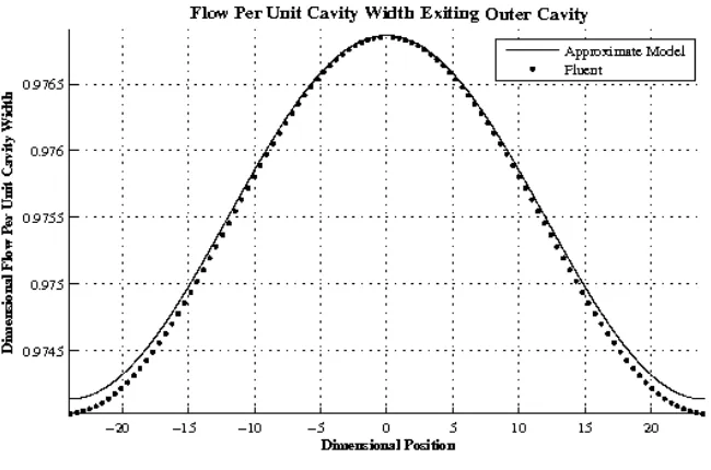
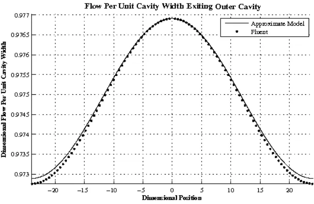
7.22 Proposed Outer Cavity Design Newtonian Flow Per Unit Cavity Width
Profile . . . 115
7.23 Proposed Outer Cavity Design Non-Newtonian Flow Per Unit Cavity Width
Profile . . . 115
List of Tables
5.1 Simulation Parameters General for All Cross Sections in the Computation of
the Outer Cavity Shape Factor . . . 37
5.2 Simulation Parameters Specific to the Triangular 15.0-15.0 Cross Section in
the Computation of the Outer Cavity Shape Factor . . . 48
5.3 Simulation Parameters Specific to the Triangular 30.0-30.0 Cross Section in
the Computation of the Outer Cavity Shape Factor . . . 49
5.4 Simulation Parameters Specific to the Triangular 30.0-60.0 Cross Section in
the Computation of the Outer Cavity Shape Factor . . . 50
5.5 Triangular 15.0-15.0 ANSYS Fluent Outer Cavity Shape Factor Data Summary 53
5.6 Triangular 15.0-15.0 Curve Fitting Constants Summary . . . 53
5.7 Triangular 15.0-15.0 Fitted Curve Outer Cavity Shape Factor Data Summary 54
5.8 Triangular 30.0-30.0 ANSYS Fluent Outer Cavity Shape Factor Data Summary 56
5.9 Triangular 30.0-30.0 Curve Fitting Constants Summary . . . 56
5.10 Triangular 30.0-30.0 Fitted Curve Outer Cavity Shape Factor Data Summary 57
5.11 Triangular 30.0-60.0 ANSYS Fluent Outer Cavity Shape Factor Data Summary 59
5.12 Triangular 30.0-60.0 Curve Fitting Constants Summary . . . 59
5.13 Triangular 30.0-60.0 Fitted Curve Outer Cavity Shape Factor Data Summary 60
5.14 Triangular 15.0-15.0 Approximated Outer Cavity Shape Factor Data Summary 64
5.15 Triangular 30.0-30.0 Approximated Outer Cavity Shape Factor Data Summary 66
5.16 Triangular 30.0-60.0 Approximated Outer Cavity Shape Factor Data Summary 68
6.1 Simulation Parameters Specific to the Triangular 30.0-60.0 Long Slot Cross
Section in the Computation of the Outer Cavity Shape Factor . . . 76
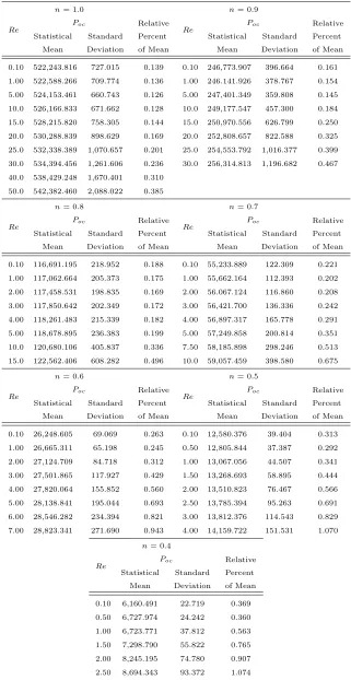
6.2 Triangular 30.0-60.0 Long Slot ANSYS Fluent Pressure Statistical Data
Sum-mary . . . 78
6.3 Simulation Parameters Specific to the Triangular 30.0-60.0 Three
7.1 Simulation Parameters Specific to the Triangular 30.0-60.0 Flat Bottom 0.316
Cross Section in the Computation of the Outer Cavity Shape Factor . . . 95
7.2 Simulation Parameters Specific to the Triangular 30.0-60.0 Flat Bottom 0.416
Cross Section in the Computation of the Outer Cavity Shape Factor . . . 96
7.3 Simulation Parameters Specific to the Triangular 30.0-60.0 Flat Bottom 0.516
Cross Section in the Computation of the Outer Cavity Shape Factor . . . 97
7.4 Proposed Outer Cavity Design Wall Shear Stress Statistical Data Summary . 98
7.5 Triangular 30.0-60.0 Flat Bottom 0.316 ANSYS Fluent Outer Cavity Shape
Factor Data Summary . . . 103
7.6 Triangular 30.0-60.0 Flat Bottom 0.316 Curve Fitting Constants Summary . 103
7.7 Triangular 30.0-60.0 Flat Bottom 0.316 Fitted Curve Outer Cavity Shape
Factor Data Summary . . . 104
7.8 Triangular 30.0-60.0 Flat Bottom 0.416 ANSYS Fluent Outer Cavity Shape
Factor Data Summary . . . 106
7.9 Triangular 30.0-60.0 Flat Bottom 0.416 Curve Fitting Constants Summary . 106
7.10 Triangular 30.0-60.0 Flat Bottom 0.416 Fitted Curve Outer Cavity Shape
Factor Data Summary . . . 107
7.11 Triangular 30.0-60.0 Flat Bottom 0.516 ANSYS Fluent Outer Cavity Shape
Factor Data Summary . . . 109
7.12 Triangular 30.0-60.0 Flat Bottom 0.516 Curve Fitting Constants Summary . 109
7.13 Triangular 30.0-60.0 Flat Bottom 0.516 Fitted Curve Outer Cavity Shape
Factor Data Summary . . . 110
7.14 Proposed Outer Cavity Design Outer Cavity Damping Dimensionless Group
Data Summary . . . 112
7.15 Proposed Outer Cavity Design Outer Cavity Damping Factor Data Summary 114
Nomenclature
Roman
Aoc Area of the outer cavity . . . 22
¯ Aoc Dimensionless area of the outer cavity . . . 22
c1 Rheological and model specific fitting constant . . . 52
c2−8 Model specific fitting constants . . . 52
cp Fluid specific heat . . . 33
Et Total energy . . . 33
~ F Body force vector . . . 32
~ G Gravitational force vector . . . 32
h Fluid enthalpy . . . 33
His Height of the inner slot . . . 48
Hoc Height of the outer cavity . . . 48
Hos Height of the outer slot . . . 18
Fluid species number . . . 33
J Diffusion flux vector . . . 33
k Fluid thermal conductivity . . . 33
Lf b Length of the outer cavity flat bottom . . . 95
Lis Length of the inner slot . . . 48
Loc Length of the outer cavity . . . 15
Los Length of the outer slot . . . 18
m Fluid consistency . . . 14
Mc Characteristic mesh size . . . 48
n Power law index . . . 14
P Pressure . . . 32
Poc Outer cavity pressure . . . 16
¯ Poc Dimensionless outer cavity pressure . . . 16
˙¯ Poc Lowest order perturbation of the dimensionless outer cavity pressure . . . 18
qa Average flow per unit cavity width . . . 16
qis Flow per unit cavity width in inner slot . . . 22
¯ qis Dimensionless flow per unit cavity width in inner slot . . . 25
¨ ¯ qis First order perturbation of the dimensionless flow per unit cavity width in inner slot . . . 26
qos Flow per unit cavity width in outer slot . . . 16
¯ qos Dimensionless flow per unit cavity width in outer slot . . . 16
¨ ¯ qos First order perturbation of the dimensionless flow per unit cavity width in outer slot . . . 17
Qoc Volumetric flow along outer cavity . . . 22
¯ Qoc Dimensionless volumetric flow along outer cavity . . . 25
˙¯ Qoc Lowest order perturbation of the dimensionless volumetric flow along the outer cavity . . . 26
¨¯ Qoc First order perturbation of the dimensionless volumetric flow along the outer cavity . . . 26
~ R Position vector . . . 15
Re Reynolds number . . . 16
¯ Re Scaled Reynolds number . . . 52
SE Energy source . . . 33
SM Mass Source . . . 32
t Time . . . 32
T Temperature . . . 33
Tr Reference temperature . . . 33
~ V Velocity vector . . . 15
Va Average velocity . . . 33
Vx x-component of velocity . . . 16
¯ Vx Dimensionless x-component of velocity . . . 16
˙¯ Vx Lowest order perturbation of the dimensionless x-component of velocity . . . 17
¨¯ Vx First order perturbation of the dimensionless x-component of velocity . . . . 17
Vy y-component of velocity . . . 16
¯ Vy Dimensionless y-component of velocity . . . 16
˙¯ Vy Lowest order perturbation of the dimensionless y-component of velocity . . . 17
¨ ¯ Vy First order perturbation of the dimensionless y-component of velocity . . . . 17
Vz z-component of velocity . . . 16
¯ Vz Dimensionless z-component of velocity . . . 16
˙˜
Vz Lowest order superposition of the first order dimensionless z-component of
velocity . . . 20
¨˜ Vz First order superposition of the first order dimensionless z-component of velocity 20 ¨ ˘ Vz Constructed form of the first order superposition of the first order dimension-less z-component of velocity . . . 21
Wis Width of the inner slot . . . 86
Woc Width of the outer cavity . . . 15
Wos Width of the outer slot . . . 86
x Spatial coordinate . . . 15
¯ x Dimensionless spatial coordinate . . . 15
y Spatial coordinate . . . 15
¯ y Dimensionless spatial coordinate . . . 15
Y Mass fraction . . . 33
z Spatial coordinate . . . 15
¯ z Dimensionless spatial coordinate . . . 15
Greek αι Condensed Fourier coefficient . . . 28
βι Condensed Fourier coefficient . . . 28
˙ γ Fluid rate of strain . . . 14
δ Ratio of the outer cavity length to width . . . 15
ǫ Measure of flow perturbation . . . 16
ε Outer cavity damping factor . . . 29
η Fluid viscosity . . . 14
ηc Characteristic fluid viscosity . . . 16
¯ η Dimensionless fluid viscosity . . . 16
˙¯ η Lowest order perturbation of the dimensionless fluid viscosity . . . 17
¨¯ η First order perturbation of the dimensionless fluid viscosity . . . 17
θ Entrance angle in outer cavity . . . 48
ι Fourier mode number . . . 28
λoc Outer cavity shape factor . . . 22
ξ Integration variable . . . 28
ρ Fluid density . . . 16
σ Anticipated outer slot back pressure dimensionless group . . . 18
ς Outer cavity damping dimensionless group . . . 27
τ Fluid shear stress . . . 32
Chapter 1
Die Design Fundamentals
In a number of manufacturing processes, extrusion or coating dies are often employed
to distribute a uniform, two dimensional liquid film over a solid surface. These films are
often formed as an intermediate step in the manufacture of polymeric sheet products, of
which several layers may be applied simultaneously. A high degree of thickness uniformity
in each of these layers can be extremely important for acceptable quality of the final
prod-uct. Demanding applications require the film thickness nonuniformity to be as little as one
percent across the entire coating surface. Therefore, such stringent requirements necessitate
[image:18.595.217.399.473.719.2]optimized design as well as precision manufacturing.
Chapter 1: Die Design Fundamentals
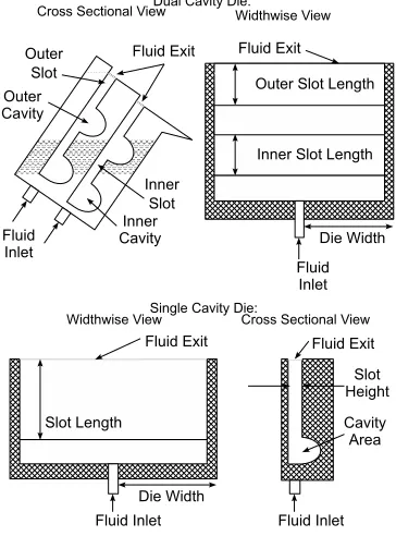
The simplest possible coating die design consists of a single cavity and slot (Fig. 1.1).
Typically, fluid is supplied to the center of the cavity, which acts as a distribution manifold,
redistributing fluid from the inlet along the width of the die. A narrow slot joins the cavity,
through which fluid is extruded and emerges at the slot exit to form the liquid film. In more
complex but often superior designs, a secondary cavity and slot are added to improve flow
distribution while increasing the robustness and operating range of the design.
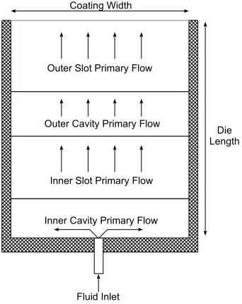
As fluid enters the die through the inlet, flow in the inner cavity is predominantly oriented
widthwise along the cavity axis, and thus resembles flow in a duct (Fig. 1.2). To achieve this
redistribution of fluid along the widthwise direction, the resistance to flow in the cavity is
made low by choosing a relatively large cross sectional area. In contrast, the slot geometry
is designed such that the resistance to flow is high, accomplished by choosing a relatively
small slot height and long slot length. As a result, fluid entering the inner cavity tends to
distribute widthwise, before secondary flows direct the fluid through the slot, where flow
consequently becomes oriented primarily along the length of the die toward the slot exit.
In a dual cavity coating die design, the functions of the inner cavity and slot are identical
to those of the single cavity coating die design. In contrast, significant flow occurs in the
cross section of the outer cavity between the exit of the inner slot and entrance to the outer
slot, such that the primary flow of the outer cavity is no longer oriented widthwise along
[image:19.595.218.389.474.689.2]the cavity axis but predominantly perpendicular to the axis along the length of the die.
Figure 1.2: Dual Cavity Coating Die Primary Flow Orientation
Chapter 1: Die Design Fundamentals
by maintaining a constant cavity pressure, such that, if the flow is subject to atmospheric
conditions at the slot exit, the coating film would be widthwise uniform. It is important
to note that a constant cavity pressure cannot be obtained with a finite sized cavity, and
so for a coating die with cavity and slot dimensions which are independent of the cavity
width, perfect widthwise uniformity cannot be accomplished. In principal this pressure drop
cannot be eliminated, as it is required for the redistribution of fluid across the entire width
of the die, although it is possible that recoverable pressure from inertia may cancel a portion
of the viscous pressure losses.
Geometric adjustments, such as widthwise cavity area and slot length variations, may
be chosen to counteract these pressure variations, however, such a design can only ensure
perfect flow uniformity for a particular fluid and flow condition. If the cavity and slot
dimensions designed to optimize flow uniformity for a particular fluid and flow condition
are used to deliver flows of differing fluid rheology, the flow uniformity can deteriorate
rapidly and its effect can overcompensate flow profiles (Fig. 1.3). It is important to note
that this pressure variance is necessary for the redistribution of flow across the entire width
of the die; therefore a more practical consideration of die design is to minimize the pressure
drop along the cavity with respect to the average cavity pressure, and thus minimize flow
nonuniformity.
Figure 1.3: Compensation Effects of Geometric Adjustments on Flow Profile
In the coating industries, a single coating die may be utilized to deliver a variety of
Chapter 1: Die Design Fundamentals
design is to deliver, with a single die, the largest range of fluids and flow conditions to within
specified uniformity limits. To achieve this goal, theoretical models for fluid flow in dies are
a valuable tool to identify the impact of geometrical adjustments, as well as allow for the
prediction of flow uniformity and design performance. There are two principal techniques
used for the prediction of optimal die geometry and the analysis of flow uniformity at the slot
exit, full numerical computation of the complete, unsimplified equation set and approximate
models.
Full numerical computation utilizes the complete set of three dimensional equations
governing fluid flow to extract the precise details of the flow and pressure fields at each
node point specified within the cavity and slot geometry. These equations are well known,
therefore various commercially available software packages can be used to generate solutions
to the equations. However, these governing equations are nonlinear in nature, and with the
iterative algorithms used by such packages, there is no guarantee a solution will converge.
For the case of coating die design, fine mesh resolution is required to adequately capture
the disparate geometrical and flow characteristics in the cavity and slot regions, as well as
the rapid changes in flow characteristics as the fluid transitions from one region to another.
With each adjustment in the process of dual cavity coating die design through numerical
computation, the revised geometry of the current iteration must be remeshed, initialized, and
the numerical solution of the flow details recomputed before further analysis and adjustments
can be made. Thus, although very accurate, the three dimensional computational solutions
are numerically intensive, often requiring long computational times to accurately simulate
a single die flow condition, and for this reason it is difficult to optimize coating die design
solely through the use of full numerical computation.
In the alternative approximate modeling approach, the complete set of three dimensional
equations governing fluid flow are averaged across the cavity cross section. Although the
precise knowledge and details of the flow and pressure fields at each node point specified
within the cavity and slot geometry are lost, average flow properties such as cavity pressure,
widthwise volumetric flow through the cavity, and volumetric flow per width in the slot are
readily obtained in exchange. The advantage of these simplified approximate models is that
they are much easier to solve, allowing for many flow conditions and geometric parameters
to be tested quickly and without redefinition of a computational model and mesh. The
shortcoming of the approximate modeling approach is that the governing equations are
approximations of the complete three dimensional set, and thus, although quantifiable,
there is some incurred error in their use.
The best theoretical approach, based on the previous arguments, would utilize a
Chapter 1: Die Design Fundamentals
coating die design. The modeling approach can be used to determine reasonable designs
for a suitable range of flow conditions and fluid rheology, and from these designs the most
promising can be scrutinized by the more precise three dimensional numerical computation,
identifying adjustments required in the design to correct approximation errors in the
mod-eling approach. The combined use of approximate models and three dimensional numerical
Chapter 2
Literature Overview
Much of the initial work on theoretical single cavity die design and the approximate
modeling approach focused on the viscous dominated analysis of both the cavity and slot
regions for a generalized Newtonian fluid obeying a power law dependence of viscosity on
shear rate. Such models utilize the common assumption that the cavity volumetric flow,
and therefore the axial pressure gradient for designs in which the cavity area does not taper,
gradually vary as fluid leaks into the slot. Despite this leakage of flow from the cavity
to the slot regions, the pressure drop flow relationship is assumed to have a locally fully
developed form, similar to the Poiseuille relationship for Newtonian flow in a pipe. Once
flow has transitioned from the cavity to the slot region, the pressure drop flow relationship
is assumed to be that of unidirectional flow between parallel plates. Therefore, the initial
theoretical single cavity die design and viscous dominated analysis are one dimensional in
nature, and the governing equations for fluid flow are spatially dependent upon position
along the cavity width only.
For the initial approximate modeling approach and viscous dominated analysis of single
cavity coating dies, closed form analytical solutions relating pressure drop to axial position
along the cavity for simple geometries of constant circular cross sectional area cavities and
straight slots were examined (Carley, 1954). Since this initial work, such viscous dominated
analyses have been expanded to incorporate more complex geometries, for which the cavity
cross sectional area, slot lengths, and slot heights may vary widthwise along the die (Durst
et al., 1994; Leonard, 1985b; Liu et al., 1994; Weinstein and Ruschak, 1996a,b). In all of
these analyses, the general form of the pressure drop flow relationship remains that of a
locally fully developed form associated with constant geometric dimensions, thus neglecting
entrance and end effects at the respective regions of the cavity, to present a one dimensional,
closed form analytical solution relating pressure drop to axial position along the cavity.
Chapter 2: Literature Overview
inertial and gravitational forces were neglected due to the balance of viscous and pressure
forces in the cavity. However, Leonard (1985b) has generalized the viscous dominated model
to include these inertial and gravitational effects within the cavity, discussing when these
effects become significant in coating die design. In the derivation of his cavity equation, the
approximations of the complete set of three dimensional equations governing fluid flow are
identical to the approach used by Huang and Yu (1973) to describe flow in porous ducts. It
is important to note that from his cavity equation, the aforementioned viscous dominated
model may be obtained when such inertial and gravitational effects are neglected.
In most theoretical analyses, the description of flow in the cavity region is treated
sep-arately from that of the slot region. However, Vrahopoulou (1991) presents an integrated
analysis of die performance, coupling the flow in the cavity and slot regions. It is important
to note here that a two dimensional Hele Shaw analysis has been used to examine flows in
coating die geometries for which the boundaries of the slot region are considerably sloped,
demonstrating good agreement with the one dimensional lubrication approximation in the
limit as the die aspect ratio becomes small. Since the purpose of practical coating die design
is to obtain a widthwise uniform liquid film at the slot exit, where any design with significant
widthwise variation in flow would not be accepted, and the length of the slot is typically
greatly exceeded by the width of the coating die, Durst et al. (1994) argues that the one
dimensional slot equation of Leonard (1985b) would be reasonable to utilize.
For the approximate, one dimensional modeling approach of single cavity coating dies,
numerous forms of the cavity momentum equations have been proposed when inertial effects
within the cavity are considered significant to the analysis of flow uniformity. To rectify
the differences between the various proposed cavity equation forms, Weinstein and Ruschak
(1996b) have formalized the derivation of the cavity equation through asymptotic
simpli-fications, specifically indicating the assumptions essential to their use. The derived cavity
equation and differential equation system is found to be identical to that of Leonard (1985b)
for single cavity coating dies.
For all of the analyses cited above, shear thinning behavior in the cavity and slot has
been characterized as a generalized Newtonian fluid obeying a power law dependence of
viscosity on shear rate. The typical rheological curves of polymers may approach a constant
Newtonian viscosity at low and high rates of strain, making the power law model
inade-quate to predict flow nonuniformities for fluids that may be classified as moderately shear
thinning. Due to the disparate rates of strain in the cavity and slot of an coating die, flow in
portions of the cavity may exhibit Newtonian behavior, while at the same time, flow in the
slot may exhibit power law rheology (Yuan, 1995). There are models which do overcome this
com-Chapter 2: Literature Overview
plexity cannot easily be implemented in the one dimensional approximate model approach.
Through a linearization of the one dimensional equations, Weinstein and Ruschak (1996a)
have demonstrated how derived analytic switching criteria are used to determine whether
the flow can effectively be viewed as either Newtonian or power law in both the cavity and
slot regions as a whole.
Following the rigorous proof of Weinstein and Ruschak (1996b) to clarify the differences
in modeling the inertial effects of the various proposed cavity equation forms, Yu et al. (1997)
examine the validity of the different one dimensional approaches through comparison of three
dimensional finite element simulations. Their results have indicated that the approximate,
one dimensional modeling approach can predict the flow distributions emerging from the
slot with reasonable confidence, while the approaches of Yuan (1995) and Weinstein and
Ruschak (1996a) can handle both Newtonian and shear thinning behavior of the cavity and
should be favorable in the theoretical analysis of single cavity coating die design.
Demanding applications in the photographic industry require the film thickness
nonuni-formity to be as little as one percent across the entire coating surface; therefore in more
complex but often superior designs, a secondary cavity and slot are added to improve flow
distribution while increasing the robustness and operating range of the design. In a dual
cavity coating die design, the function of the inner cavity and slot is identical to those
re-spective of the single cavity coating die design. Here, the primary flow of the inner cavity is
predominantly oriented widthwise along the cavity axis, and thus resembles flow in a duct,
before secondary flows direct the fluid through the slot, where flow consequently becomes
oriented primarily along the length of the die toward the slot exit (Figure 1.2). In contrast,
significant flow occurs in the cross section of the outer cavity between the exit of the inner
slot and entrance to the outer slot, such that the primary flow of the outer cavity is no
longer oriented widthwise along the cavity axis but predominantly perpendicular to the axis
along the length of the die.
For the purely viscous flow of a Newtonian fluid, the equations for flow along the width
and cross section of the outer cavity are independent; however, as recognized by Leonard
(1985a), nonlinearities occurring due to inertia couple the flow, and the equations for the
outer cavity become three dimensional in nature. The inertia of this cross flow impedes
widthwise redistribution along the outer cavity, and thus the damping ability of the outer
cavity to improve flow uniformity is diminished. Despite this complication of flow in the
outer cavity, much of the initial work on theoretical dual cavity design directly applied
the established governing equations of flow in the inner cavity to both the inner and outer
cavities of the approximate models (Leonard, 1985a; Lee and Liu, 1989; Yuan, 1995).
Chapter 2: Literature Overview
of dual cavity coating dies, utilizing a perturbation technique to derive a flow equation
which accounts for the three dimensional nature of the outer cavity flow and considers the
nonlinearities occurring due to inertia or generalized Newtonian rheology. Since the flow
uniformity of practical coating die design cannot vary more than a few percent across the
entire coating width, an asymptotic technique is justified and thus linearizes the governing
equations of momentum and mass conservation about small deviations in the flow per unit
cavity width exiting the inner slot. The components of the momentum equation in the
cross section of the outer cavity indicate that the pressure perturbation varies widthwise
along the die but is uniform over the outer cavity cross section, and thus the resulting form
of the governing equation of flow along the axis of the outer cavity becomes analogous to
the convective heat transfer equation with internal heat generation. Furthermore, Ruschak
and Weinstein (1997b) have designed a dual cavity coating die analytically through the
asymptotic solution of their equations for which the flows in the inner and outer cavities are
coupled.
Much of the theoretical single and dual cavity die design and the approximate modeling
approach focused on the derivation of the general form of the governing equation and
pres-sure drop flow relationship for more complex geometries where the cavity shape and cross
sectional area vary widthwise along the die. Additional parameters, known as shape factors,
are necessary inputs to the approximate die design models which incorporate the specific
cross sectional shape of the cavity into the pressure drop flow relationship. By
approximat-ing the velocity field in the inner cavity as fully developed in any cross section, the viscous
and kinetic shape factors explicitly arise (Leonard, 1985b; Weinstein and Ruschak, 1996b).
A similar, yet differing, shape factor for the outer cavity arises (Ruschak and Weinstein,
1997a), which is identical to that of the viscous shape factor for the inner cavity under
conditions of creeping flow, relating the pressure drop to fully developed flow in a duct.
However, if fluid inertia is present or the rheological model is that of a generalized Newtonian
fluid, such as a power law dependence of viscosity on shear rate, the flow across the outer
cavity cross section and along the outer cavity axis are coupled. The generalized outer cavity
shape factor accounts for the effects of the flow field in the cross section of the outer cavity,
specifically those of fluid inertia and a shear rate dependent viscosity, on the redistribution
of flow along the outer cavity axis.
The accurate prediction of the pressure drop flow relationship for the laminar flow of
generalized Newtonian fluids through ducts of arbitrary yet constant cross section is
essen-tial for the determination of the necessary shape factor inputs to approximate die design
models. A variational method evolved from an expression of the principal of minimum
Chapter 2: Literature Overview
the velocity profiles in rectangular ducts, from which the friction factor Reynolds number
correlation, or cavity viscous shape factor, has been determined (Schechter, 1961). The
velocity profiles of power law fluids in rectangular ducts were also solved through the finite
difference method (Wheeler and Wissler, 1965), from which a three parameter expression
for the viscous shape factor was correlated through a least squares regression which was
then verified experimentally. Since this initial work, the prediction of the pressure drop flow
relationship has been expanded to incorporate more complex geometries of arbitrary cross
section, where the geometric parameters required in the expression of Wheeler and Wissler
(1965) to characterize the duct geometry have been tabulated through the finite element
method (Liu, 1983).
A different approach to predict pressure losses has been proposed by Kozicki et al. (1966),
through which an expression is derived in terms of two geometric parameter constants
characteristic of the shape of the duct cross section, whose determination for more complex
geometries requires Newtonian flow data, and a function of shear stress characterizing the
fluid. In a much simpler empirical method, Miller (1972) suggests there exists a universal
curve relating the average shear rate to the average wall shear stress for the flow of a
given generalized Newtonian fluid through ducts of arbitrary cross section. Such a curve is
obtained through flow experiments or calculations in a duct of simple geometry, such as that
of a circular duct, from which the pressure drop flow relationship is obtained for any duct
of arbitrary cross section through the knowledge of the Newtonian viscous shape factor.
Theoretical models for fluid flow in coating dies are a valuable tool to identify the impact
of geometrical adjustments, as well as allow for the prediction of flow uniformity and design
performance. For the approximate, one dimensional modeling approach of single cavity
coating dies, the pressure drop flow relationship for cavity geometries of irregular cross
section provides the necessary inputs to analyze flow widthwise distribution and thickness
uniformity quickly and effectively. Hanks (1974) and Liu and Hong (1988) examine the
analytical basis of Miller’s method for estimating the pressure drop flow relationship for
a generalized Newtonian rheology, observing several restrictions to the original method,
defining limits of applicability, and proposing additional methods to supplement Miller’s
basic technique.
The final coating die designs obtained through the use of approximate models must be
examined experimentally, as this is the ultimate test and validation for any of the theoretical
approaches discussed. However, in order to perform a meaningful experimental verification
of lateral flow uniformity, the coating die must be built with the proper dimensional aspect
ratios and precisely machined. Such a coating die is prohibitively expensive, and academic
infor-Chapter 2: Literature Overview
mation regarding the die flow experiments performed in industry are considered proprietary
and seldom released; even there, reliable data is difficult to obtain while conclusive results
are often elusive (Ruschak, 2010). For this reason, the validity of theoretical one
dimen-sional approximate die design models and the governing pressure drop flow relationships are
examined in academic literature through the use of three dimensional numerical simulation;
whereas such an approach is widely accepted within industry as well, when experiments are
difficult to quantify.
Fluid flow in single and dual cavity coating dies is three dimensional in nature, and
thus the most accurate approach to the analysis of widthwise flow uniformity is to solve the
complete set of three dimensional equations governing fluid flow, without simplifications,
through numerical computation. This technique extracts the precise details of the flow and
pressure fields at each node point specified within the cavity and slot geometry. Three
dimensional finite element methods are a valuable tool to identify secondary flows within
the cavity and slot flow fields, such as regions of stagnation and vortex formation.
A study of the three dimensional flow fields of generalized Newtonian fluids concerning
the entrance region and inlet effects of single cavity coating dies has been examined by Wen
and Liu (1994). The center fed and end fed inlet designs have been analyzed for the effects
of inertial force, fluid rheology, and inlet geometry on flow uniformity and local vortex
for-mation, while theoretical predictions have been qualitatively confirmed experimentally by
the observation of streamlines through a flow visualization technique. For center fed inlet
designs, strong jetting effects of increased fluid inertia cause a “fountaining effect” peak in
the flow distribution confined to the central region of the coating width. For end fed inlet
designs, strong jetting effects of increased fluid inertia cause the appearance of two
undesir-able vortices near the inlet entrance region, with a peak in flow distribution near the cavity
end. Although a number of the theoretical approximate die design models incorporate the
effects of fluid inertia in their analysis, three dimensional numerical simulation is necessary
for the prediction, and ultimate elimination, of entrance effects and vortex formation at the
inlet region.
Similar to the analysis of entrance effects in the inlet regions of single and dual cavity
coating dies, three dimensional numerical simulation is a valuable tool for the prediction of
vortex formation in the cross flow of the outer cavity regions of a dual cavity coating die.
Flow patterns of fluids obeying a power law dependence of viscosity on shear rate within
semicircular and tear drop outer cavity cross sections were computed by the finite element
method to reveal the formation of vortices with increased fluid inertia. A relationship has
been derived for the critical Reynolds number as a function of power law index, above which
Chapter 2: Literature Overview
the expansion and contraction angles, as well as the rheological properties of polymeric
fluids on vortex formation in the outer cavity of a dual cavity coating die have also been
examined by Lee et al. (1990). Again, a relationship for the critical Reynolds number, above
which vortex formations are found to occur, has been presented as a function of power law
index and expansion angle, and a flow visualization technique was used to observe the flow
field patterns in the outer cavity experimentally. While the theoretical approximate die
design models allow for the quick and efficient determination of general coating die design
geometrical parameters, such as the required cross sectional area of the cavity domain, two
and three dimensional numerical simulation is necessary for the detailed analysis of specific
cavity shape and ultimate geometrical design.
While much of the complete three dimensional numerical simulation approaches focused
on stagnation and vortex formation within the cross section of the outer cavity, general three
dimensional finite element codes have also been developed for the purpose of widthwise flow
distribution analysis. Wang (1991) has discussed the effects of coating die geometry on film
thickness uniformity, concluding that a uniform widthwise flow distribution may be obtained
if the contour of the cross section of the slot geometry were to be machined with a “dog
bone profile”. Several design variations, such as the discharge of coating solutions at the
cavity end have been examined to eliminate stagnant regions and reduce flow nonuniformities
caused by production variations (Liu et al., 1994).
There are two principal techniques used for the prediction of optimal die geometry and
the analysis of flow uniformity at the slot exit, full numerical computation and approximate
models. The modeling approach can be used to determine reasonable designs for a suitable
range of flow conditions and fluid rheology. From these designs the most promising can
be scrutinized by the more precise three dimensional numerical computation, identifying
adjustments required in the design to correct approximation errors in the modeling approach
(Lee and Liu, 1989; Liu et al., 1994). Such three dimensional computational solutions are
numerically intensive, often requiring long computational times to accurately simulate a
single die flow condition, and for this reason the most advantageous design approach utilizes
a combination of the approximate models and numerical computation for the most efficient
coating die design process.
The experimental validation of current theoretical approximate die design models through
the verification of lateral flow uniformity is difficult, owing to the fact that the coating die
must be built with the proper dimensional aspect ratios and precisely machined, making
phenomena occurring within the individual cavities difficult to measure. Computational
Fluid Dynamics offers valuable information to the internal flow details, yet such an analysis
Chapter 2: Literature Overview
dual cavity coating die designs has been lacking while the mesh generation for the numerical
computations cited has been coarse. The focus of this research is to utilize Computational
Fluid Dynamics as idealized experimental data, which is to be used for the improvement
and verification of simplified approximate models as well as provide the first numerical
com-putations for the generalized outer cavity shape factor proposed by Ruschak and Weinstein
Chapter 3
Derivation of the Outer Cavity
Approximate Model
Demanding applications in industry require the film thickness nonuniformity to be as
small as one percent across the entire coating surface. Therefore, in more complex but often
superior designs, a secondary cavity and slot are added to improve flow distribution. For
the purely viscous flow of a Newtonian fluid, the equations for flow along the width and
cross section of the outer cavity are independent, however, nonlinearities occurring due to
inertia or non-Newtonian rheologies couple the flow, and the equations of motion for the
outer cavity become nonlinear. When the flow uniformity of the liquid film exiting the outer
slot can vary by no more than a few percent, perturbation methods are applicable and the
flow equations are linearized about the limiting case of perfect uniformity.
The derivation of the outer cavity approximate model utilizes the complete set of three
dimensional equations of motion that govern the flow in the outer cavity of a dual
cav-ity coating die design. Here, the complete set of three dimensional governing momentum
equations are applied for generalized Newtonian rheologies with a power law dependence of
viscosity on shear rate, where the viscosity of the fluid may be expressed as a function of
the magnitude of the rate of strain tensor.
η=m|γ˙|n−1
(3.0.1)
where
|γ˙|2= ∐∆
2 (3.0.2a)
Chapter 3: Derivation of the Outer Cavity Approximate Model
∆ij =
∂Vi
∂Rj
+ ∂Vj
∂Ri
(3.0.2c)
Disparate length scales typical of coating die design give rise to small parameters, which
are summarized below, that enable simplifications to the complete set of three dimensional
governing momentum and continuity equations. These simplifications are achieved through
scaling each of the components and considering the relative order of magnitude of terms,
which is the basis of asymptotic analysis.
Figure 3.1: Detailed View of the Outer Cavity Geometry Symmetric About the Inlet Plane
For consistency in the final form of the derived approximate model, the characteristic
length of the outer cavity cross section (Fig. 3.1) is chosen to be the length of the outer
cavity, while the axial characteristic length is chosen to be the width of the outer cavity.
As a result of this scaling, a small parameter arises in the derivation of the outer cavity
approximate model, defined as the ratio of the outer cavity length to width.
¯
x= x
Loc
¯
y= y
Loc
¯
z= z
Woc
(3.0.3a)
δ= Loc
Woc
(3.0.3b)
The characteristic flow per unit cavity width in the outer slot is chosen to be the average
flow per unit cavity width, and is used to construct the dimensionless velocity components in
the governing momentum and continuity equations. The characteristic velocity was defined
to be the ratio of this characteristic flow per unit cavity width and the respective dimensional
Chapter 3: Derivation of the Outer Cavity Approximate Model
¯
qos=
qos
qa
(3.0.4a)
¯
Vx=
VxLoc
qa
¯
Vy=
VyLoc
qa
¯
Vz=
VzWoc
ǫqa
(3.0.4b)
For generalized Newtonian rheologies with a power law dependence of viscosity on shear
rate, a characteristic viscosity is defined in the outer cavity such that the characteristic
viscosity of the outer cavity is equivalent to the Newtonian viscosity for a power law index
of unity.
¯
η= η
ηc
(3.0.5a)
ηc =
m n
qa
(Loc)2
o1−n (3.0.5b)
The pressure forces in the outer cavity must balance the anticipated axial flow in the
outer cavity along the width of the die, and therefore a characteristic pressure in the outer
cavity is chosen to balance the leading viscous and pressure terms in the governing equations
of motion.
¯
Poc=
Poc(Loc)2
ηcqa
(3.0.6)
From the preceding scalings, the following form of the Reynolds number arises in the
complete set of dimensionless governing equations of motion in the outer cavity.
Re=ρqa
ηc
(3.0.7)
Introducing the aforementioned dimensionless variables, the derivation of the outer
cav-ity approximate model begins with the dimensionless form of the complete set of three
dimensional governing momentum and continuity equations.
Continuity Equation
∂V¯x
∂x¯ +
∂V¯y
∂y¯ +δ
2ǫ∂V¯z
∂¯z = 0 (3.0.8a)
X-Component of Momentum
Re
¯
Vx
∂V¯x
∂x¯ + ¯Vy
∂V¯x
∂y¯ +δ
2 ǫV¯z
∂V¯x
∂z¯
=−∂P¯oc
∂x¯ +
∂ ∂x¯
¯
η∂V¯x ∂x¯
+∂η¯
∂x¯
∂V¯x
∂x¯ +
∂ ∂y¯
¯
η∂V¯x ∂¯y
+∂η¯
∂y¯
∂V¯y
∂x¯ +δ
2 ∂
∂z¯
¯
η∂V¯x ∂¯z
+δ2ǫ∂η¯ ∂¯z
∂V¯z
∂x¯
Chapter 3: Derivation of the Outer Cavity Approximate Model
Y-Component of Momentum
Re
¯
Vx
∂V¯y
∂x¯ + ¯Vy
∂V¯y
∂y¯ +δ
2ǫV¯
z
∂V¯y
∂z¯
=−∂∂P¯y¯oc + ∂
∂¯x
¯
η∂V¯y ∂x¯
+∂η¯
∂x¯
∂V¯x
∂y¯ +
∂ ∂y¯
¯
η∂V¯y ∂y¯
+∂η¯
∂y¯
∂V¯y
∂¯y +δ
2 ∂
∂z¯
¯
η∂V¯y ∂z¯
+δ2ǫ∂η¯ ∂z¯
∂V¯z
∂y¯
(3.0.8c)
Z-Component of Momentum
ǫRe
¯
Vx
∂V¯z
∂x¯ + ¯Vy
∂V¯z
∂y¯ +δ
2 ǫV¯z
∂V¯z
∂z¯
=−∂P¯oc
∂z¯ +ǫ
∂ ∂x¯
¯
η∂V¯z ∂¯x
+∂η¯
∂x¯
∂V¯x
∂z¯ +ǫ
∂ ∂y¯
¯
η∂V¯z ∂y¯
+∂η¯
∂y¯
∂V¯y
∂z¯ +δ
2 ǫ∂
∂z¯
¯
η∂V¯z ∂z¯
+δ2ǫ∂η¯ ∂z¯
∂V¯z
∂z¯
(3.0.8d)
Viscosity ¯
η 2
n−1 = 2
"
∂V¯x
∂x¯
2
+
∂V¯y
∂y¯
2
+δ4ǫ2
∂V¯z
∂z¯
2#
+
∂V¯x
∂y¯ +
∂V¯y
∂x¯
2
+δ2
∂V¯x
∂z¯ +ǫ
∂V¯z
∂x¯
2
+δ2
∂V¯y
∂z¯ +ǫ
∂V¯z
∂y¯
2
(3.0.8e)
If the flow per unit cavity width exiting the inner cavity and inner slot exhibits perfect
widthwise uniformity, there is no damping effect in the outer cavity as flow passes directly
through to the outer slot unaffected. In this scenario, flow in the outer cavity is governed by
only the cross sectional components of momentum conservation. This two dimensional flow
field in the outer cavity cross section, driven by uniform flow in the inner slot, is considered
the base flow and the starting point for the perturbation analysis. When there is small
widthwise variation in the flow per unit cavity width exiting the inner slot, nonuniformities
in the profile are represented as a deviation from the average flow, or perfect widthwise
uniformity condition. Considering the necessary requirements for acceptable coating die
design, where a significant widthwise variation in the the flow per unit cavity width exiting
the outer slot would not be accepted, asymptotic methods are utilized to expand the system
about the limiting case of perfect widthwise flow uniformity.
¯
qos= 1 +ǫq¨¯os+O(ǫ2) (3.0.9a)
¯
Vx= ˙¯Vx+ǫV¯¨x+O(ǫ2) (3.0.9b)
¯
Vy = ˙¯Vy+ǫV¯¨y+O(ǫ2) (3.0.9c)
¯
Vz=ǫV¨¯z+O(ǫ2) (3.0.9d)
¯
Chapter 3: Derivation of the Outer Cavity Approximate Model
Due to the typical aspect ratios demonstrated in a dual cavity coating die design (Fig. 3.1),
as the width of the outer cavity generally greatly exceeds the length or height of the outer
cavity cross section, it is thus anticipated that the back pressure of the outer slot greatly
exceeds pressure variations in the cross section of the outer cavity. Therefore, in the
deriva-tion of the outer cavity approximate model, the pressure drop along the length of the outer
slot determines a uniform pressure in the cross section of the outer cavity while the pressure
distribution in the outer cavity varies axially along the coating die width. It is important
to note that the absolute pressure in the outer cavity does not influence the flow field, as it
is the pressure gradient along the outer cavity axis which drives the axial flow responsible
for damping variations in the flow per unit cavity width exiting the inner slot. Based on
this reasoning, the dimensionless perturbed pressure in the outer cavity is constructed in a
form which includes the anticipated dominant back pressure of the outer slot.
¯
Poc= [σ{1 +nǫq¨¯os}] + ˙¯Poc+ǫP¨¯oc+O(ǫ2) (3.0.10a)
where
σ= 2
1+n
2 + 1
n n
(Loc)2nLos
(Hos)2n+1
(3.0.10b)
For the typical geometry of a dual cavity coating die design (Fig. 3.1), the characteristic
length of the outer cavity cross section is small compared to the axial characteristic length
of the outer cavity; consequently, the ratio of these characteristic lengths is much less than
order unity. Substituting the asymptotic expansions (Eqs. 3.0.9a to 3.0.9e and 3.0.10a) into
the dimensionless form of the complete set of three dimensional governing momentum and
continuity equations (Eqs. 3.0.8a to 3.0.8e), the derivation of the outer cavity approximate
model considers the simplification to the governing momentum and continuity equations in
the limit as the flow perturbation and this ratio of the outer cavity length to width approach
zero, holding the Reynolds number of the flow condition fixed.
Lowest Order:
Continuity Equation
∂V˙¯x
∂x¯ +
∂V˙¯y
∂y¯ = 0 (3.0.11a)
X-Component of Momentum
Re "
˙¯
Vx
∂V˙¯x
∂x¯ + ˙¯Vy
∂V˙¯x
∂y¯
#
=−∂P˙¯oc
∂x¯ +
∂ ∂x¯
(
˙¯
η∂V˙¯x ∂x¯
)
+∂η˙¯
∂x¯
∂V˙¯x
∂¯x + ∂ ∂y¯
(
˙¯
η∂V˙¯x ∂y¯
)
+∂η˙¯
∂¯y ∂V˙¯y
∂x¯
Chapter 3: Derivation of the Outer Cavity Approximate Model
Y-Component of Momentum
Re "
˙¯
Vx
∂V˙¯y
∂x¯ + ˙¯Vy
∂V˙¯y
∂y¯
#
=−∂P˙¯oc
∂y¯ +
∂ ∂x¯
(
˙¯
η∂V˙¯y ∂x¯
)
+∂η˙¯
∂x¯
∂V˙¯x
∂y¯ +
∂ ∂y¯
(
˙¯
η∂V˙¯y ∂y¯
)
+∂η˙¯
∂y¯
∂V˙¯y
∂y¯
(3.0.11c)
Z-Component of Momentum
∂P˙¯oc
∂z¯ = 0 (3.0.11d)
Viscosity ˙¯
η 2
n−1 = 2
(
∂V˙¯x
∂x¯
)2
+
( ∂V˙¯y
∂y¯
)2
+
( ∂V˙¯x
∂y¯ +
∂V˙¯y
∂x¯
)2
(3.0.11e)
Through a qualitative examination of the lowest order system above, the pressure drop
along the width of the coating die in the outer cavity is negligible, and thus there is no
redistribution of the flow per unit cavity width along the axis of the outer cavity. Consistent
with the definition of the flow per unit cavity width perturbation (Eq. 3.0.9a), this confirms
the expectation that in the solution of the lowest order system, the flow per unit cavity
width exiting the inner cavity and inner slot exhibits the perfect widthwise uniformity of
ideal coating die design. Therefore, there is no damping effect in the outer cavity as the two
dimensional flow field in the outer cavity cross section passes directly through to the outer
slot unaffected.
If the cavity and slot dimensions designed to optimize flow uniformity for a particular
fluid and flow condition are used to deliver flows of differing fluid rheology, the flow
uni-formity can deteriorate rapidly (Fig. 1.3). Therefore, the primary interest of coating die
design is the peak to peak variation in the widthwise distribution of the flow per unit cavity
width exiting the outer slot. As evident from the examination of the lowest order system
(Eqs. 3.0.11a to 3.0.11e) and the definition of the flow per unit cavity width perturbation
(Eq. 3.0.9a), the system equations in the first order contain the nonuniformity information,
and the solution of this system is necessary for the determination of the desired peak to
peak variation in widthwise flow uniformity.
First Order:
Continuity Equation
∂V¨¯x
∂x¯ +
∂V¨¯y
Chapter 3: Derivation of the Outer Cavity Approximate Model
X-Component of Momentum
Re "
˙¯
Vx
∂V¨¯x
∂x¯ + ¨V¯x
∂V˙¯x
∂x¯ + ˙¯Vy
∂V¨¯x
∂y¯ + ¨V¯y
∂V˙¯x
∂y¯
#
=−∂P¨¯oc
∂x¯
+ ∂
∂¯x "( ˙¯ η∂ ¨ ¯ Vx
∂x¯
)
+
(
¨ ¯
η∂V˙¯x ∂x¯
)#
+∂η˙¯
∂x¯
∂V¨¯x
∂x¯ +
∂η¨¯
∂x¯
∂V˙¯x
∂x¯
+∂
∂y¯
"( ˙¯ η∂ ¨ ¯ Vx
∂y¯
)
+
(
¨ ¯
η∂V˙¯x ∂y¯
)#
+∂η˙¯
∂y¯
∂V¨¯y
∂x¯ +
∂η¨¯
∂y¯
∂V˙¯y
∂x¯
(3.0.12b)
Y-Component of Momentum
Re "
˙¯
Vx
∂V¨¯y
∂x¯ + ¨V¯x
∂V˙¯y
∂x¯ + ˙¯Vy
∂V¨¯y
∂y¯ + ¨V¯y
∂V˙¯y
∂y¯
#
=−∂ ¨ ¯
Poc
∂y¯
+ ∂
∂x¯
"( ˙¯ η∂ ¨ ¯ Vy
∂x¯
)
+
(
¨ ¯
η∂V˙¯y ∂x¯
)#
+∂η˙¯
∂x¯
∂V¨¯x
∂y¯ +
∂η¨¯
∂¯x ∂V˙¯x
∂y¯
+∂
∂y¯
"( ˙¯ η∂ ¨ ¯ Vy
∂y¯
)
+
(
¨ ¯
η∂V˙¯y ∂y¯
)#
+∂η˙¯
∂y¯
∂V¨¯y
∂y¯ +
∂η¨¯
∂y¯
∂V˙¯y
∂y¯
(3.0.12c)
Z-Component of Momentum
Re "
˙¯
Vx
∂V¨¯z
∂x¯ + ˙¯Vy
∂V¨¯z
∂y¯
#
=− ∂
∂x¯
σnq¨¯os
−∂
¨ ¯
Poc
∂z¯ +
∂ ∂x¯
( ˙¯ η∂ ¨ ¯ Vz
∂x¯
)
+∂η˙¯
∂x¯
∂V¨¯x
∂z¯ +
∂ ∂y¯
( ˙¯ η∂ ¨ ¯ Vz
∂y¯
)
+∂η˙¯
∂y¯
∂V¨¯y
∂z¯
(3.0.12d)
Viscosity ¨¯
η= 2{n−1}η˙¯
n−1
3−n
"( ∂V˙¯x
∂x¯
∂V¨¯x
∂x¯
)
+
( ∂V˙¯y
∂y¯
∂V¨¯y
∂y¯
)
+ 1 2
( ∂V˙¯x
∂y¯ +
∂V˙¯y
∂¯x )(
∂V¨¯x
∂y¯ +
∂V¨¯y
∂x¯
)# (3.0.12e)
In the derivation of the outer cavity approximate model, it is anticipated that the back
pressure of the outer slot dominates pressure variations in the cross section of the outer
cavity, and thus the pressure drop along the length of the outer slot determines a uniform
pressure in the cross section of the outer cavity. The pressure distribution in the outer
cavity varies axially along the width of the coating die due to variations in the widthwise
flow distribution exiting the inner slot, therefore a superposition of the axial component of
velocity in the outer cavity is introduced.
¨ ¯
Chapter 3: Derivation of the Outer Cavity Approximate Model
First Order:
Z-Component of Momentum
Re "
˙¯
Vx
∂V¨˜z
∂x¯ + ˙¯Vy
∂V¨˜z
∂y¯
#
=−∂
∂¯z
nq¨¯os
+ ∂
∂x¯
( ˙¯ η∂ ¨ ˜ Vz
∂x¯
)
+ ∂
∂y¯
( ˙¯ η∂ ¨ ˜ Vz
∂y¯
)
(3.0.14)
Upon inspection of the first order system of equations (Eqs. 3.0.12a to 3.0.12c, 3.0.12e
and 3.0.14), it is important to note that the axial component of velocity is now the only
surviving component of the perturbation velocity in the axial component of momentum,
while it does not appear in the remaining system equations. In the quasi two dimensional
flow field assumed as the base flow in the outer cavity cross section, the components of the
flow field scale with a respective increase or decrease in the local flow per unit cavity width
entering the outer slot. Along the width of the coating die, the axial pressure gradient
drives the flow responsible for damping nonuniformities in the flow per unit cavity width
exiting the inner slot, and thus the axial component of velocity scales with the local pressure
gradient.
¨ ˜
Vz=
−∂
∂¯z n
nq¨¯oso
¨ ˘
Vz (3.0.15)
First Order:
Z-Component of Momentum
Re "
˙¯
Vx
∂V¨˘z
∂x¯ + ˙¯Vy
∂V¨˘z
∂y¯
#
= 1 + ∂
∂x¯
( ˙¯ η∂ ¨ ˘ Vz
∂x¯
)
+ ∂
∂y¯
( ˙¯ η∂ ¨ ˘ Vz
∂y¯
)
(3.0.16)
For the derivation of the outer cavity approximate model, the perturbed set of three
dimensional equations (Eqs. 3.0.11a to 3.0.11c, 3.0.11e and 3.0.16) governing fluid flow in
the outer cavity are averaged across the cavity cross section. Although the precise knowledge
and details of the flow and pressure fields at each node point specified within the cavity and
slot geometry are lost, average flow properties such as cavity pressure, widthwise volumetric
flow through the cavity, and volumetric flow per width in the slot are obtained in exchange.
Therefore, neglecting entrance and end effects at the respective regions of the cavity, a one
dimensional, closed form analytical solution relating pressure drop to axial position along
the cavity may be presented.
The solution to the perturbed set of three dimensional equations (Eqs. 3.0.11a to 3.0.11c,
3.0.11e and 3.0.16) governing fluid flow in the outer cavity of a dual cavity coating die
may be obtained numerically with no slip boundary conditions imposed at the surfaces
of the domain. With the flow field profiles in the outer cavity cross section determined,
the postulated form of the axial velocity component, scaled with the local axial pressure
gradient, is integrated over the dimensionless area of the outer cavity cross section to provide
the desired relationship between the axial pressure gradient and volumetric flow along the
Chapter 3: Derivation of the Outer Cavity Approximate Model Z Z ¯ Aoc ¨ ˜
Vzdxd¯ y¯=−
∂ ∂¯z
n nq¨¯oso
Z Z
¯
Aoc ¨ ˘
Vzdxd¯ y¯ (3.0.17)
The form of the integrated axial velocity component is similar to that which appears in
the derivation of the single cavity approximate model, where the viscous shape factor for
one dimensional flow through a duct of arbitrary cross section was defined. In a similar
fashion to the derivation of the single cavity approximate model, the pressure at the exit
of the outer slot in a dual cavity coating die design is assumed to be at negligible gauge
pressure. Therefore, the desired one dimensional approximate model, in dimensional form,
relating the axial pressure gradient and volumetric flow along the outer cavity through the
outer cavity shape factor is obtained.
Qoc=−
(Aoc)2λoc
ηc
∂Poc
∂z (3.0.18a)
where
λoc=
RR
¯
Aoc ¨ ˘
Vzdxd¯ y¯
"
RR
¯
Aoc