Effects of curvature on rarefied gas flows between rotating
concentric cylinders
Nishanth Dongari,a)Craig White,b) Thomas J. Scanlon,c)Yonghao Zhang,d) and Jason M. Reesee)
James Weir Fluids Lab, Department of Mechanical & Aerospace Engineering, University of Strathclyde, Glasgow G1 1XJ, United Kingdom
(Received 26 November 2012; accepted 22 April 2013; published online 23 May 2013)
The gas flow between two concentric rotating cylinders is considered in order to investigate non-equilibrium effects associated with the Knudsen layers over curved surfaces. We investigate the nonlinear flow physics in the near-wall regions using a new power-law (PL) wall-scaling approach. This PL model incorporates Knudsen layer effects in near-wall regions by taking into account the boundary limiting effects on the molecular free paths. We also report new direct simulation Monte Carlo results covering a wide range of Knudsen numbers and accommodation coefficients, and for various outer-to-inner cylinder radius ratios. Our simulation data are compared with both the classical slip flow theory and the PL model, and we find that non-equilibrium effects are not only dependent on Knudsen number and accommodation coefficient but are also significantly affected by the surface curvature. The relative merits and limitations of both theoretical models are explored with respect to rarefaction and curvature effects. The PL model is able to capture some of the nonlinear trends associated with Knudsen layers up to the early transition flow regime. The present study also illuminates the limitations of classical slip flow theory even in the early slip flow regime for higher curvature test cases, although the model does exhibit good agreement throughout the slip flow regime for lower curvature cases. Torque and velocity profile comparisons also convey that a good prediction of integral flow properties does not necessarily guarantee the accuracy of the theoretical model used, and it is important to demonstrate that field variables are also predicted satisfactorily.
C
2013 AIP Publishing LLC. [http://dx.doi.org/10.1063/1.4807072]
I. INTRODUCTION
Isothermal gas flow between two concentric rotating cylinders is a classical fluid dynamics problem that is detailed for the no-slip case in many well-known textbooks (e.g., Schlichting1).
However, under certain rarefied conditions the flow between the cylinders can exhibit highly non-intuitive behaviour. For example, if the outer cylinder is stationary and the inner cylinder is rotating, it is possible for the velocity profile to becomeinverted, i.e., the velocity willincreasefrom the inner to the outer cylinder wall. This unusual flow phenomenon was first described theoretically by Einzel
et al.2 for the case of liquid helium. Using the direct simulation Monte Carlo (DSMC) technique, Tibbset al.3extended the analysis to the case of a rarefied gas and demonstrated that velocity inversion could occur provided the tangential momentum accommodation coefficient (TMAC) for the surfaces was small. This early work has led to a number of theoretical and simulation studies for rotating Couette flow4–12and oscillating Couette flow.13These confirmed the existence of velocity inversion
a)Electronic mail:nishanth.dongari@strath.ac.uk b)Electronic mail:craig.white@strath.ac.uk c)Electronic mail:tom.scanlon@strath.ac.uk d)Electronic mail:yonghao.zhang@strath.ac.uk e)Electronic mail:jason.reese@strath.ac.uk
for small values of TMAC and also showed there was a critical accommodation coefficient.14,15 Indeed, Yuhonget al.5derived an analytical criterion for the critical accommodation coefficient and
showed that velocity inversion was solely dependent on the value of TMAC at the stationary outer cylinder.
Yuhonget al.5also discussed the limitations of classical slip flow theories: they are only
appli-cable up toKn∼0.1. This has generally led to second-order treatments of the velocity slip at solid bounding surfaces,16but with limited success because this approach fails to reproduce the nonlinear
stress/strain-rate relationship observed in the Knudsen layer (KL).10,17–19 The behaviour of a
rar-efied gas in the Knudsen layer can accurately be predicted by the Boltzmann equation.20,21However,
directly solving the Boltzmann equation for practical gas flow applications remains computationally intensive due to the complicated structure of the molecular collision term. Other alternatives are to introduce a slip coefficient that depends on the Knudsen number22 or to introduce an effective viscosity term.23,24 Cercignani used kinetic theory to propose a “wall-function” that scales with the mean free path.20This function complements the constitutive relation by effectively modifying the viscosity, and is able to capture some non-equilibrium behaviour of the Knudsen layer. This idea has been adopted and extended16,25–28with some success.
Dongari et al.29 carried out molecular dynamics (MD) simulations of gases and the results
indicate that molecules perform L´evy-type flights30under rarefied conditions, i.e., the free paths of
gas molecules follow a power-law (PL) distribution. Consequently, these authors hypothesised that the probability distribution function for the molecular free paths of a rarefied gas followed a PL form, and this was validated against MD data under various rarefied conditions. Using a PL distribution to describe free paths, Dongariet al.31and Dongariet al.32derived effective mean free path (MFP)
models for flows confined by planar and non-planar surfaces, respectively, by taking into account the solid boundary effects. PL effective MFP models showed good agreement with the MD data up to the early transition regime (Kn ∼1), while classical exponential MFP scaling models33,34 are
limited up toKn∼0.2. In addition, these authors modified the Navier-Stokes constitutive relations and slip boundary conditions using PL-based MFP scaling and were then able to accurately capture several non-equilibrium effects in the Knudsen layer for both isothermal and thermal gas flows.
On the other hand, particle simulation methods such as DSMC35 and MD36 not only provide excellent alternatives to solve rarefied gas flows, but also aid in rigorously validating these kinds of extended hydrodynamic models. Existing simulations for cylindrical Couette flows3,37do not cover a wide range of Knudsen numbers, and they are only carried out for limited ratios of radii of the outer (R2) to inner (R1) cylinders. Tibbset al.3 presented DSMC results forKn=0.5, withR2/R1
=5/3, while Kim’s37 MD numerical experiments are conducted forKn0.01, withR
2/R1 =5.
Although Jung38 has performed MD simulations for various radii ratios, theR
2/R1 values in this
work are quite large (5) and the rotating inner cylinder may have lesser influence on the velocity profile results.
There is also a scarcity of torque data for the rotating Couette flow test case. The existing experimental data can be traced back to Kuhlthau,39 however, these experiments were performed
for a set-up where the length of the inner cylinder is comparable to its radius. It has been mentioned by Agrawal and Prabhu,14 that one needs to incorporate a correction factor to match the classical
theories in the continuum regime.
In view of the above, we carry out rigorous DSMC simulations of cylindrical Couette gas flow for Knudsen numbers covering the slip (Kn=0.1) and transition flow regime (Kn=0.5 and 1). At eachKn, a variety of TMAC (σ) andR2/R1 values are used to check the sensitivity of surface and
curvature effects, respectively. The resultant velocity and torque data are compared with the classical slip theory and the new PL wall scaling model.31,32A brief overview of our DSMC simulations and
the PL wall-scaling model are outlined in Secs.II–IV.
II. DSMC SIMULATIONS
We investigate gas flows in the transition flow regime, so the DSMC method35 is chosen to
FIG. 1. Contours of velocity calculated bydsmcFoamfor a typical concentric cylindrical Couette flow case.
and collisions are decoupled. Particle movements are handled deterministically according to the particle velocity vectors and the simulation time step. Binary inter-molecular collisions and surface interactions are dealt with in a probabilistic manner. Macroscopic properties are recovered as a spatial and time average of the microscopic particle properties.
The DSMC solver used in this paper is dsmcFoam, an open source solver that is part of the free-to-download C++ fluid dynamics toolbox, OpenFOAM.40 This solver has previously been rigorously validated for a variety of benchmark cases.41,42Two-dimensional DSMC simulations of cylindrical Couette flows are reported in the present paper, where argon gas is trapped between two concentric cylinders. The inner cylinder is rotating and the outer cylinder is stationary. Our simulations do not utilise quarter or half symmetry: a full circular domain is modelled as shown in Figure1.
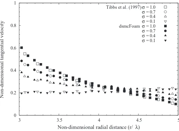
As validation fordsmcFoamfor rarefied, low-speed cylindrical Couette flow, results are com-pared to previous DSMC results for the transition regime with hard sphere STP argon as the working gas.3 The inner cylinder has a radiusR
1 of 1.875×10⁻⁷ m and the outer cylinder’s radiusR2 is
3.125×10⁻⁷m, which givesR
2/R1=5/3. The Knudsen number based on the hard sphere mean free
pathλ(6.33×10⁻⁸m) and the gap between the two cylinders is 0.5. The inner cylinder rotates with
a constant velocity of 96.94 m/s, giving a Mach number of 0.3. Excellent agreement with previous
0 0.2 0.4 0.6 0.8 1
3 3.5 4 4.5 5
Non-dimensional tangential velocity
Non-dimensional radial distance (r/ λ)
Tibbs et al. (1997) σ = 1.0
σ = 0.7
σ = 0.4
σ = 0.1 dsmcFoam σ = 1.0
σ = 0.7
σ = 0.4
[image:3.612.156.453.494.712.2]σ = 0.1
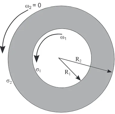
FIG. 3. Schematic of Couette flow between concentric rotating cylinders.
results for the normalised velocity profiles with four different accommodation coefficients (1.0, 0.7, 0.4, and 0.1) can be observed in Figure2.
For all of the remaining DSMC simulations reported in this paper, the numerical cell size is chosen such that the cells are much smaller than the mean free path, and so that enough cells are placed throughout the domain to recover macroscopic properties with sufficient resolution. The Knudsen number is based on the ratio of the unconfined mean free path value (λ) to the radial distance between the cylinder surfaces (R2−R1). The time step is smaller than the mean collision
time, and also small enough that particles are likely to spend multiple time steps within a single computational cell. All simulations are initialised with at least 20 DSMC particles per cell, and 500 000 particles in the whole domain. Each case was solved in parallel on 4 cores of the 1100 core High Performance Computer (HPC) facility at the University of Strathclyde. The run time for each case was around 60 h to achieve a total of at least 300 000 samples. The variable hard sphere collision model43is used to perform collisions, and all surface-particle interactions are dealt with as a mixture of specular and diffuse interactions in order to simulate various accommodation coefficients. The torque on the rotating inner cylinder is calculated from the measured viscous drag force acting on the inner cylinder surface.
Numerical results are obtained for a variety of outer-to-inner cylinder radius ratios (R2/R1
=6/5, 5/3, 2, 3, and 5), Knudsen numbers (0.1, 0.5, and 1.0) and accommodation coefficients (0.1, 0.4, 0.7, and 1.0), as shown in Figure 3. The inner cylinder is rotating at a Mach number (Ma = R1ω/
√
γRT) of 0.20 for all simulated test cases. Hereωis the angular velocity of the inner cylinder,γ the ratio of the specific heat capacities,Rthe gas constant, andTthe temperature. The surface temperature of both cylinders is constant at 273 K. The radii ratio is varied by fixingR1and
increasingR2, andKn is maintained constant by proportionally modifying the gas density. As the
Mach number is fixed, the Reynolds number (Re =Ma/Kn√πγ /2) remains constant for different geometric configurations, as long asKnis constant.
III. POWER-LAW WALL SCALING MODEL
Close to a solid boundary, gas molecule-surface interactions start to dominate gas inter-molecular collisions. Hence, the gas MFP will effectively be reduced in the near-wall regions, leading to a nonlinear variation of MFP with surface normal distance.33This leads to the formation of a KL: a
local thermodynamically non-equilibrium region extending∼O(λ) from the surface.21The state of
Dongariet al.32,44derived a PL-based effective MFP model for non-planar surfaces by incorpo-rating the effects of curvature. They developed a curvature-dependent MFP solution for both convex and concave surfaces, and extended this analysis to deduce the effective MFP for a gas confined between two concentric cylinders. In the present paper, we incorporate this power-law wall scaling model developed for cylindrical surfaces into the Navier-Stokes equations. The non-planar MFP so-lution reduces to the planar wall MFP model31when the curvature tends to zero and the non-planar
solution also satisfies other limiting conditions.32
The current setup has gas confined between two co-axial cylinders. In this context, the curvature effects are induced due to both the convex (inner cylinder) and the concave (outer cylinder) nature of the surfaces, and it is very important to capture this nonlinear behaviour accurately. For example, in the case of planar parallel walls, it is equally probable that a molecule travels towards one surface or the other.31 However, in the present case solid angle theory is used to determine the likelihood of a molecule travelling in the direction of cylinder, as opposed to travelling towards the bulk or other cylinder. From this weighting, the general expression for the effective mean free path of a gas is obtained.32 The convex surface (inner cylinder) overpredicts gas MFP compared to a planar case, while the concave surface (outer cylinder) underpredicts it. This stems from the fact that gas molecules near a convex surface have more probability to travel towards the bulk, while they have smaller probability near a concave surface.32 The differences between these over- and
underpredictions are magnified with increase inR2/R1. So the curvature effects are very important
for the current power-law model and used to modify the Navier-Stokes equations to explore the nonlinear physics associated with the Knudsen layers of rarefied gas flows confined between rotating co-axial cylinders.
A. Effective mean free path
The complete expression for the normalised (by the conventional unconfined MFP) effective mean free path of a gas confined between two concentric cylinders is32,44
β = θ−
u
π 1−
1 θ− u θ− u 0
1+ R −(r, θ−)
a
(1−n)
dθ− + 1− θ− u
π 1−
1 θ+ u θ+ u 0
1+ R +(r, θ+)
a
(1−n)
dθ+
, (1)
with
θ−
u =arcsin R1 r , (2) θ+
u =π−θu−, (3)
R−(r, θ−)=rcos(θ−)− (rcos(θ−))2+R2
1−r2, (4)
R+(r, θ+)= −rcos(θ+)+ (rcos(θ+))2+R22−r2, (5)
whereris the distance of a molecule from the centre of the co-axial cylinders andR−the travelling distance limit for a molecule moving towards the inner cylinder surface, for a given zenith angle
θ−. The largest travelling distance R−
u is achieved for the zenith angle directionθu−, above which
the molecule bypasses the cylinder surface and travels into the bulk or towards the outer cylinder surface. The molecule has a travelling distance ofR+to the outer cylinder surface for a travelling direction ofθ+.
R2/R1. The Knudsen number is defined as
Kn = λ
R2−R1
. (6)
The power-law exponentnacts as a decisive parameter to define the extent of deviation from equilibrium. For larger values of n (→ ∞) the PL distribution function simply reduces to the classical exponential one,45i.e., molecules follow Brownian motion rather than L´evy-type flights.30 For a finite n, the distribution function describes a system deviating from equilibrium. Through MD simulations, Dongariet al.29,31 determined that annvalue of 3 in both the slip and transition regimes gave very good results for both isothermal and thermal gas flows in planar and non-planar geometries.32Therefore, we usen=3 for all of our PL model results presented in this paper, although
we recognise that the value of this parameter should usefully be the subject of future investigations.
B. Shear flow between two parallel plates
The physics of Knudsen layers is best illustrated through a simple set-up of shear flow between two parallel plates. Ansumaliet al.18provided the exact solution to the hierarchy of nonlinear lattice Boltzmann kinetic equations for the stationary planar Couette flow test case. They presented not only the slip velocity results as a function of Knudsen number, but also the shear stress and normal stress difference, which arise due to the non-continuum effects. Other researchers have also carried out studies on planar Couette flow in order to analyse Knudsen layer effects in near-wall regions.10,19,46
The flow is assumed to be fully developed, one-dimensional, isothermal, laminar, and steady, with a low Reynolds number (Re) so that inertial effects may be neglected. AsMa2Kn2is assumed to be very small, non-continuum effects which trigger a normal stress difference are also negligible. With these assumptions, the governing equation and the first-order slip boundary condition for planar Couette flow can be given as
∂ ∂y
βPL∂
U ∂y
=0, (7)
Usli p =Uw−C1Kn
βPL∂
U ∂y
w,
(8)
where βPL is the normalised effective mean free path in planar geometries,29,31 Uw is the wall
velocity, andC1is the first-order slip velocity coefficient (taken as unity).
The distance between the two parallel plates isH, and they are set aty= ±H/2. The Knudsen number is given by Kn=λ/H. The upper and lower plates move with a constant velocity Uw = ±50 m s−1, in opposite directions, and the external acceleration ax =ay =0. Energy transfer
considerations are not included at this stage, but the plate temperatures are considered to be equal and constant to allow the properties of the gas flow to be determined. Equation(7)is numerically solved for the normalised axial velocity profilesU∗by applying the slip boundary condition(8)at the upper and lower walls (i.e., aty∗= ±0.5). A second-order slip boundary condition has not been implemented, as the higher order term reduces to zero due to Eq.(7).
In Figure4, we compare our PL model with the DSMC data, and results of the R13 and R26 equations,46 in order to illustrate the predictive capabilities of our Navier-Stokes based continuum equations relative to other extended hydrodynamic models. We chose to compare our results with the DSMC data of Gu and Emerson,46as their simulations are carried out for a very low Mach number, which is consistent with our assumption of neglecting inertial forces. In the early transition regime, Kn =0.25, the velocity profile predicted by the R13 equations is linear. In the core part of the flow (i.e., outside of the Knudsen layer), all three hydrodynamic models are in agreement with the DSMC data.46However, in the region close to the wall, the DSMC results indicate a Knudsen-layer
0 0.1 0.2 0.3 0.4 0.5 0
0.2 0.4 0.6 0.8 1
Knudsen number (Kn ) = 0.25
Power−law model R26
R13 DSMC
0 0.1 0.2 0.3 0.4 0.5
0 0.2 0.4 0.6 0.8 1
Knudsen number (Kn ) = 0.5
Power−law model R26
R13 DSMC
0 0.1 0.2 0.3 0.4 0.5
0 0.2 0.4 0.6 0.8 1
Knudsen number (Kn ) = 0.75
Power−law model R26
R13 DSMC
0 0.1 0.2 0.3 0.4 0.5
0 0.2 0.4 0.6 0.8 1
Knudsen number (Kn ) = 1
Power−law model R26
[image:7.612.109.502.88.515.2]R13 DSMC
FIG. 4. Normalised half channel velocity profiles for planar Couette flow at various Knudsen numbers. Comparison of our power-law (PL) model results with the DSMC data, and the R26 and R13 moment equations.46
equations fail to capture this aspect of the velocity profile, and overpredict the amount of velocity slip. In contrast, the results from the PL model are in very good agreement with both the DSMC data and the R26 equations, and the new model not only predicts the correct velocity slip but also, and more importantly, captures the power-law behaviour of the velocity profile in the Knudsen layer,47
even up toKn=1.0.
IV. CYLINDRICAL COUETTE FLOW
A. Governing equations
equation in cylindrical coordinates is 1 r2 d dr
r2τrφ=0, (9)
whereris the radial coordinate,φis the tangential coordinate, andτrφis the tangential stress, which
is defined as
τrφ=μ
duφ dr − uφ r , (10)
whereμis the fluid dynamic viscosity anduφis the velocity of the fluid in the tangential direction. From the kinetic theory of gases, the fluid viscosity can be understood in terms of the collisions between gas molecules, and of the free paths of molecules between collisions. The unconfined MFP is then related to the shear viscosity:48
μ=ρ√ λ
π/2RT, (11)
whereρis the gas density,Rthe specific gas constant, andTthe gas temperature.
Equation(11)is only valid for flows that are in quasi-equilibrium. Within the Knudsen layer, the flight paths of the gas molecules are affected by the presence of a surface. If the unconfined expression for the MFP,λ, is replaced by our geometry-dependent mean free path for the non-planar case,λeff=λβthrough Eq.(1), we obtain a non-constant, geometry-dependent, effective viscosity,
μeff, that can then be used to deduce a nonlinear stress/strain-rate relation:
τrφ=μβ μeff duφ dr − uφ r . (12)
Substituting Eq.(12)into Eq.(9)results in the modified governing equation:
μ r2
d dr
r2β
duφ dr − uφ r
=0. (13)
This model needs to be solved in conjunction with the following slip boundary conditions at the inner and outer cylinder surfaces, respectively,
uφ |r=R1=ω1R1+
2−σ1
σ1 α1 λ β duφ dr − uφ r
r=R1
, (14)
uφ |r=R2=ω2R2−
2−σ2
σ2 α2 λ β duφ dr − uφ r
r=R2
, (15)
whereω1andω2are the angular velocities andσ1andσ2are the tangential momentum
accommo-dation coefficients of the inner and outer cylinders, respectively. The solution for the velocity profile can then be obtained as
uφ(r)=r
ω1+
α1λC
R13 +G(r)C
, (16)
where
G(r)=
r
R1 dr
r3β, (17)
C= ω2−ω1 H1+αR13λ
1 + α2λ
R3 2
, (18)
H1= R2
R1 dr
When the effects of the Knudsen layer are neglected, i.e., the mean free path has no geometry dependence, then Eq.(16)simply reduces to the velocity profile based on the classical slip solution, as presented in Yuhonget al.5
The accurate prediction of integral flow parameters in micro-/nano-conduits is important in engineering MEMS devices. Here, the torque exerted on the rotating inner cylinder is given as
= f A R1, (20)
with
f =
μeff
duφ dr −
uφ r
r=R1
, (21)
A=2πR1L, (22)
whereLis the length of the inner cylinder.
When the no-slip boundary condition is applied and the Knudsen layer effects are negligible, the torque expression for flows in the continuum regime is14
C=
4πμωL
1
R2 1 −
1
R2 2
. (23)
V. RESULTS AND DISCUSSION
Normalised velocity profiles [U∗=uφ/(ω1R1)] are presented in Figures5–11for various
Knud-sen numbers andR2/R1values, and different combinations of accommodation coefficients. To
high-light the phenomenon of velocity inversion, the outer cylinder is kept stationary (ω2 =0) and the
inner cylinder is allowed to rotate. For an initial study, the ratio of the radii of the inner and outer cylindersR2/R1 is chosen to be 5/3, and the accommodation coefficients are assumed to be equal
at the inner and outer surfaces (σ1 =σ2 =σ). Figure 5(a)presents a comparison between our
[image:9.612.117.501.544.692.2]solution based on the PL effective MFP (Eq.(16)) and the DSMC data. The PL model is in excellent agreement with the simulation data for the Kn=0.1 case, at allσ values. Figure5(b)presents the results based on the classical governing equation together with the conventional slip boundary conditions, i.e., without considering any Knudsen layer effects (see Yuhonget al.5), alongside the PL model results. The classical slip model results are in good agreement with the PL, with slight deviations in the near-wall regions. ForKn=0.1, i.e., the end of the slip flow regime, no velocity inversion is predicted by either the simulation data or the theoretical models.
FIG. 5. Variation of the non-dimensional velocity [U∗=uφ/(ω1R1)] with normalised radial distance for cylindrical Couette flow withσ1=σ2=σ. Comparison of PL model results against (a) DSMC data and (b) the classical slip solution (Yuhong
FIG. 6. Variation of the non-dimensional velocity [U∗=uφ/(ω1R1)] with normalised radial distance for cylindrical Couette flow withσ1=σ2=σ. Comparison of PL model results against (a) DSMC data and (b) the classical slip solution.5The results are presented forKn=0.5 andR2/R1=5/3.
Comparisons for theKn =0.5 case are presented in Figure6. The PL model is in very good quantitative agreement with the DSMC results for theσ=1.0 and 0.7 cases. The results show that the DSMC data and PL formulation follow the same basic trends and predict an inverted velocity profile when the accommodation coefficient is 0.1. However, slight deviations are discernible at the surface of the outer cylinder for the σ =0.4 and 0.1 cases. It is interesting to note that, for the specific case of the accommodation coefficients of the inner and outer cylinders having the same value, the family of velocity profiles all pass through a common point that is independent of the value of the accommodation coefficient. This intersection point in the PL profiles is fairly close to the point predicted by the DSMC data, whereas the classical slip solution predicts this point closer to the outer cylinder, as shown in Figure6(b). The classical slip solution does not account for any variation in MFP and hence fails to capture nonlinear effects associated with the Knudsen layers at the inner and outer cylinders; it underpredicts the slip velocity at the inner cylinder and overpredicts at the outer one, i.e., accounting for larger slip effects. The discrepancies are greatest atσ =1.0 and decrease asσis reduced. At very low values ofσ, the PL model and classical slip solutions are identical and yield the same solid body rotation solution asσ→0.
Figure7 shows velocity profiles for theKn=1 case, and deviations between the PL model and DSMC data are discernible in the near-wall regions at both the inner and outer cylinders, for allσ values. The PL model underpredicts the slip velocities at the inner cylinder for allσ values; however, at the outer cylinder it overpredicts forσ =0.1, 0.4, and 0.7, and slightly underpredicts
[image:10.612.114.501.544.692.2]FIG. 8. Effect of the power-law (PL) exponent n on the cylindrical Couette flow velocity profiles. Variation of the non-dimensional velocity [U∗ = uφ/(ω1R1)] with normalised radial distance for σ1 = 1.0 and (a) σ2 = 1.0, (b)σ2=0.4, and (c)σ2=0.15, forKn=0.5 andR2/R1=5/3.
FIG. 9. Variation of the non-dimensional velocity [U∗=uφ/(ω1R1)] with normalised radial distance for cylindrical Couette flow withσ1=σ2=σ. Comparison of PL model results against DSMC data. The results are presented forKn=0.1 and
[image:11.612.111.500.382.687.2]FIG. 10. Variation of the non-dimensional velocity [U∗=uφ/(ω1R1)] with normalised radial distance for cylindrical Couette flow withσ1=σ2=σ. Comparison of PL model results against DSMC data. The results are presented forKn=0.5 and
R2/R1=6/5 (top left), 2 (top right), 3 (bottom left), and 5 (bottom right).
forσ =1. The classical slip model comparisons with the PL model are qualitatively similar to the Kn =0.5 case. The intersection point of the family of velocity profiles, for both the DSMC data and the PL model, moves towards the inner cylinder asKnincreases. However, for the classical slip model, the intersection point is found to stay at about the same location (approximately 0.7 on the abscissa) for allKncases.
As mentioned earlier, the value of the power-law exponent has been fixed ton=3 for all the reported results so far. Figure 8 demonstrates the effect of the value ofn on the structure of the velocity profile in the Knudsen layer, forσ1=1.0 and (a)σ2=1.0, (b)σ2=0.4, and (c)σ2=0.15.
The velocity profiles are almost unaffected by the value ofnat high values of the accommodation coefficients (σ2=1.0) across the entire annular clearance. For small accommodation coefficients
(σ2=0.4 and 0.15), the velocity profiles are shown to depend on the value ofn, and the sensitivity to
this increases towards the outer cylinder. However, the maximum deviation is limited to only around 3%–4%, and this is obtained withnvarying from 2.5 to 10. As mentioned in the paper, previous MD results indicate that the value ofnis around 3, and so velocity profiles may not be too sensitive to small variations inn.
To check the sensitivity of curvature effects on the velocity profiles, we now present results for
R2/R1=6/5, 2, 3, and 5 cases, and atKn=0.1, 0.5, and 1. The radii ratio is varied by fixingR1and
increasingR2, andKnis set by modifying the gas density. The Reynolds number (Re) is the same
for different geometric configurations for a givenKn, asMais kept constant.
Figure9 demonstrates the velocity profiles for theKn=0.1 case, at differentR2/R1 values.
For eachR2/R1 value, the PL model results are compared with DSMC data forσ =0.1, 0.4, 0.7,
and 1. For lowerR2/R1 values (6/5 and 2), the PL model is in excellent agreement with simulation
FIG. 11. Variation of the non-dimensional velocity [U∗=uφ/(ω1R1)] with normalised radial distance for cylindrical Couette flow withσ1=σ2=σ. Comparison of PL model results against DSMC data. The results are presented forKn=1 and
R2/R1=6/5 (top left), 2 (top right), 3 (bottom left), and 5 (bottom right).
the near-wall region at the inner cylinder. Here the PL model slightly underpredicts the wall-slip velocities for theR2/R1 =3 and 5 cases, although at the outer cylinder velocities are accurately
predicted. The profiles intersection point moves towards the outer cylinder with an increase inR2/R1.
Slip velocities decrease at both the inner and the outer cylinders with an increase inR2/R1. When
the size of the inner cylinder is relatively reduced in comparison with the outer one, relatively larger and smaller slip effects are noticed, at the inner and outer cylinders, respectively. This may be due to relatively fewer molecules interacting with the inner cylinder, compared to the outer one. On the other hand, for theR2/R1=6/5 case, no velocity inversion is observed atσ=0.1; however, partially
inverted velocity profiles are predicted in cases with higher values ofR2/R1. For partial inversions,
the gradient of the velocity profile has to be zero at some position in the annular gap, and this point moves towards the inner cylinder with an increase inR2/R1.
Similar comparisons are carried out forKn=0.5 and 1 cases, and are shown in Figures10 and11. For theR2/R1 =6/5 case, the PL model is in excellent agreement with DSMC data at
bothKn=0.5 and 1. Deviations are noticed asR2/R1increases, becoming quite significant for the
R2/R1 =5 case, especially in the near-wall region of the inner cylinder. Similar to theKn=0.1
case, the slip velocities at the inner cylinder decrease significantly with an increase inR2/R1. For
theKn=0.5 andσ =1 case, with an increase inR2/R1, the slip velocities at the inner cylinder
predicted by DSMC vary approximately from 0.73 to 0.4, whereas for the PL model from 0.72 to 0.25. For theKn=1 andσ=1 case, they vary from 0.7 to 0.38, and from 0.68 to 0.2, for the DSMC and PL model, respectively. This conveys that deviations between the PL model and our DSMC data approximately vary from 1% to 38% with an increase inR2/R1from 6/5 to 5, for theKn=0.5 and
σ =1 case. They vary from 2% to 47% with an increase inR2/R1 from 6/5 to 5, for theKn =1
10−3 10−2 10−1 100 101 10−1
100
Power−law model Classical slip model DSMC
10−3 10−2 10−1 100 101
10−1 100
Power−law model Classical slip model DSMC
10−3 10−2 10−1 100 101
10−1 100
Power−law model Classical slip model DSMC
10−3 10−2 10−1 100 101
10−1 100
Power−law model Classical slip model DSMC
Γ Γ
[image:14.612.109.501.80.472.2]Γ Γ
FIG. 12. Variation of normalised torqueexerted on the rotating inner cylinder with Knudsen number (Kn). Our DSMC data are compared with both the slip and the PL models. The data are obtained for a specific case, where the accommodation coefficients of both the inner and outer cylinders are unity (σ1=σ2=1) andR2/R1=6/5 (top left), 5/3 (top right), 3 (bottom left), and 5 (bottom right).
significant in the transition regime, which suggests that the simple power-law free path distribution function has limitations and it needs to be revisited for larger curvature geometries.
The position of the profile intersection point is relatively insensitive to a change inR2/R1 for
theKn=0.5 and 1 cases, when compared with theKn=0.1 one. On the other hand, for theR2/R1
=6/5 case, complete velocity inversion is observed atσ =0.1, and only partially inverted velocity profiles are predicted for higher values ofR2/R1, atσ =0.1. For theKn=0.5 and 1 cases, the
position where the gradient of the velocity profile becomes zero moves away from the inner cylinder with an increase inR2/R1. These findings are in contrast with the velocity profiles for theKn=0.1
case, see Figure9.
Figure 12 presents the variation of the normalised torque () exerted on the rotating inner cylinder with Knudsen number (Kn), and our DSMC data are compared with the slip and PL models. The data are obtained for a specific case, where the accommodation coefficients of both the inner and the outer cylinders are unity (σ1 = σ2 = 1), and for R2/R1 = 6/5, 5/3, 3, and
5. Torque values are normalised by the continuum-fluid values of the torque (C), see Eq. (23).
The PL model is in good agreement with the DSMC data up to Kn∼2 for R2/R1 = 6/5
deviations beyond Kn∼0.2. For cases with larger curvature (R2/R1 = 3 and 5), the PL model
also exhibits deviations fromKn∼0.2 onwards, although these are limited to 10%–15% up to Kn=1. The classical slip model predicts significant deviations even within the slip flow regime (Kn ∼0.05), which conveys that non-equilibrium effects are more pronounced for larger curvature test cases.
VI. CONCLUSIONS
The non-equilibrium flow physics of isothermal rarefied gases interacting with non-planar surfaces in cylindrical Couette flow has been described using detailed DSMC simulations for different Knudsen numbers, and a variety of accommodation coefficient values and outer-to-inner radius ratios. Simulation data have been compared with both the classical slip theory and our new PL wall scaling model, and both rarefaction and curvature effects on flow properties have been rigorously explored. Velocity profile comparisons forKn =0.1, 0.5, and 1, atR2/R1=5/3, highlight the known fact
that while the classical slip model is valid in the slip flow regime, it exhibits significant deviations in the transition regime. However, our PL wall scaling model predictions are in very good agreement up toKn∼1, with only slight deviations in the near-wall region at the inner cylinder. The simulation data and the PL model also predict partially inverted velocity profiles for moderateσvalues, whereas the classical slip model does not capture this phenomenon. The classical slip theory significantly underpredicts the velocity profile at the inner cylinder and overpredicts it at the outer cylinder, and velocity inversion is also predicted at the incorrectσvalues (see Figures6(b)and7(b)). Our torque investigations indicate that classical slip flow theory may also not be accurate enough even in the slip flow regime for larger curvature test cases.
The DSMC data of velocity profiles for largerR2/R1values illuminate the limitations of the PL
wall scaling model in the transition regime. With an increase in theR2/R1value and forKn≥0.5,
the PL model significantly underpredicts the velocity in the near-wall region of the inner cylinder, but does obtain fair comparison in the near-wall region of the outer one. This shows that the non-equilibrium effects in the near-wall region are not merely dependent on Kn, but that they are also influenced by curvature, since deviations between the DSMC data and PL model are more pronounced for largerR2/R1 values. These findings are consistent with our DSMC torque
measurements, where the deviations from continuum theory are higher for largerR2/R1(different
geometric configurations), for a givenKnandMa(i.e., a fixed Reynolds number).
Although the predictive capabilities of the PL model are fair for torque comparisons up to the transition regime, the model fails to capture some of nonlinear trends associated with the Knudsen layers at the inner cylinder, as shown in Figures10and11forR2/R1=3 and 5. Hence, torque and
velocity profile comparisons together convey that mere prediction of integral flow parameters does not guarantee the complete accuracy of any theoretical model, and it is important to demonstrate that the field variables are also in agreement with other accurate simulation data.
The major advantage of our new PL model is that it can be easily implemented in conventional computational fluid dynamics (CFD) solvers in order to produce substantially better results in Knudsen layers when compared to the classical slip model. This is very pertinent from the point of view of simulation of fluid flows in arbitrary geometries, as the DSMC method is computationally intensive. In our comparisons with DSMC data in the current paper we used the PL exponentn=3, as in previous planar test cases,29,31andn=3 may be applicable in non-planar test cases with lower
curvature. However, the current results may motivate future work into understanding the Knudsen layers in arbitrary geometries, including:
(i) rigorous molecular dynamics simulations of rarefied gases confined in arbitrary geometries and subjected to a range of complex flow conditions, for establishing properly and generally the value ofnfor non-planar cases;
(iii) revisiting the classical slip and jump boundary conditions, where were originally derived assuming constant MFP in Knudsen layers, and using geometry-dependent effective MFP models instead.
ACKNOWLEDGMENTS
The research leading to these results has received funding from the European Community’s Seventh Framework Programme FP7/2007-2013 under grant agreement ITN GASMEMS (Grant Agreement No. 215504). The author C.W. gratefully acknowledges funding from the James Weir Foundation. The author J.M.R. gratefully acknowledges funding through EPSRC Programme Grant EP/I011927/1. Our calculations were performed on the 1100 core HPC Facility of the Faculty of Engineering at the University of Strathclyde. The authors thank the reviewers for their useful comments.
1H. Schlichting and K. Gersten,Boundary Layer Theory(Springer-Verlag, Berlin, 2000).
2D. Einzel, P. Panzer, and M. Liu, “Boundary condition for fluid flow: Curved or rough surfaces,”Phys. Rev. Lett.64,
2269–2272 (1990).
3K. W. Tibbs, F. Baras, and A. L. Garcia, “Anomalous flow profile due to the curvature effect on slip length,”Phys. Rev. E
56, 2282–2283 (1997).
4K. Aoki, H. Yoshida, T. Nakanishi, and A. L. Garcia, “Inverted velocity profile in the cylindrical Couette flow of a rarefied
gas,”Phys. Rev. E68, 016302 (2003).
5S. Yuhong, R. W. Barber, and D. R. Emerson, “Inverted velocity profiles in rarefied cylindrical Couette gas flow and the
impact of the accommodation coefficient,”Phys. Fluids17(4), 047102 (2005).
6Z. Guo, B. Shi, and C. Zheng, “Velocity inversion of micro cylindrical Couette flow: A lattice Boltzmann study,”Comput.
Math. Appl.61(12), 3519–3527 (2011).
7D. A. Lockerby, J. M. Reese, D. R. Emerson, and R. W. Barber, “Velocity boundary condition at solid walls in rarefied gas
calculations,”Phys. Rev. E70, 017303 (2004).
8R. S. Myong, J. M. Reese, R. W. Barber, and D. R. Emerson, “Velocity slip in microscale cylindrical Couette flow: The Langmuir model,”Phys. Fluids17(8), 087105 (2005).
9P. Taheri and H. Struchtrup, “Effects of rarefaction in microflows between coaxial cylinders,”Phys. Rev. E80, 066317 (2009).
10P. Taheri, M. Torrilhon, and H. Struchtrup, “Couette and Poiseuille microflows: Analytical solutions for regularized
13-moment equations,”Phys. Fluids21(1), 017102 (2009).
11W. P. Yudistiawan, S. Ansumali, and I. V. Karlin, “Hydrodynamics beyond Navier-Stokes: The slip flow model,”Phys.
Rev. E78, 016705 (2008).
12D. A. Lockerby and J. M. Reese, “High-resolution Burnett simulations of micro Couette flow and heat transfer,”J. Comput.
Phys.188(2), 333–347 (2003).
13D. R. Emerson, X. J. Gu, S. K. Stefanov, S. Yuhong, and R. W. Barber, “Nonplanar oscillatory shear flow: From the continuum to the free-molecular regime,”Phys. Fluids19(10), 107105 (2007).
14A. Agrawal and S. V. Prabhu, “Deduction of slip coefficient in slip and transition regimes from existing cylindrical Couette flow data,”Exp. Therm. Fluid Sci.32(4), 991–996 (2008).
15A. Agrawal and S. V. Prabhu, “Survey on measurement of tangential momentum accommodation coefficient,”J. Vac. Sci.
Technol. A26, 634–645 (2008).
16D. A. Lockerby, J. M. Reese, and M. A. Gallis, “The usefulness of higher-order constitutive relations for describing the Knudsen layer,”Phys. Fluids17(10), 100609 (2005).
17S. Chapman and T. G. Cowling,Mathematical Theory of Non-Uniform Gases(Cambridge University Press, Cambridge, 1970).
18S. Ansumali, I. V. Karlin, S. Arcidiacono, A. Abbas, and N. I. Prasianakis, “Hydrodynamics beyond Navier-Stokes: Exact solution to the lattice Boltzmann hierarchy,”Phys. Rev. Lett.98, 124502 (2007).
19W. P. Yudistiawan, S. K. Kwak, D. V. Patil, and S. Ansumali, “Higher-order Galilean-invariant lattice Boltzmann model for microflows: Single-component gas,”Phys. Rev. E82, 046701 (2010).
20C. Cercignani,The Boltzmann Equation and its Applications(Springer, New York, 1988). 21Y. Sone,Kinetic Theory and Fluid Dynamics(Birkhauser, Boston, 2002).
22P. Bahukudumbi, J. H. Park, and A. Beskok, “A unified engineering model for steady and unsteady shear-driven gas microflows,”Microscale Thermophys. Eng.7, 291–315 (2003).
23G. Karniadakis, A. Beskok, and N. Aluru,Microflows and Nanoflows: Fundamentals and Simulation(Springer, 2005). 24N. Dongari, A. Sharma, and F. Durst, “Pressure-driven diffusive gas flows in micro-channels: From the Knudsen to the
continuum regimes,”Microfluid. Nanofluid.6(5), 679–692 (2009).
25Y. H. Zhang, X. J. Gu, R. W. Barber, and D. R. Emerson, “Capturing Knudsen layer phenomena using a lattice Boltzmann model,”Phys. Rev. E74, 046704 (2006).
26C. R. Lilley and J. E. Sader, “Velocity profile in the Knudsen layer according to the Boltzmann equation,”Proc. R. Soc.
London, Ser. A464, 2015–2035 (2008).
28N. Dongari, F. Durst, and S. Chakraborty, “Predicting microscale gas flows and rarefaction effects through extended
Navier-Stokes-Fourier equations from phoretic transport considerations,”Microfluid. Nanofluid.9, 831–846 (2010). 29N. Dongari, Y. H. Zhang, and J. M. Reese, “Molecular free path distribution in rarefied gases,”J. Phys. D44, 125502
(2011).
30M. F. Shlesinger, J. Klafter, and G. Zumofen, “Above, below and beyond Brownian motion,” Am. J. Phys.67(12),
1253–1259 (1999).
31N. Dongari, Y. H. Zhang, and J. M. Reese, “Modeling of Knudsen layer effects in micro/nanoscale gas flows,”J. Fluids
Eng.133(7), 071101 (2011).
32N. Dongari, R. W. Barber, D. R. Emerson, S. K. Stefanov, Y. H. Zhang, and J. M. Reese, “The effect of Knudsen layers on rarefied cylindrical Couette gas flows,”Microfluid. Nanofluid.14, 31–43 (2013); See also “Erratum to: The effect of Knudsen layers on rarefied cylindrical Couette gas flows,”Microfluid Nanofluid14, 905–906 (2013).
33D. W. Stops, “The mean free path of gas molecules in the transition regime,”J. Phys. D3, 685–696 (1970).
34E. J. Arlemark, S. K. Dadzie, and J. M. Reese, “An extension to the Navier-Stokes equations to incorporate gas molecular collisions with boundaries,”J. Heat Transfer132(4), 041006 (2010).
35G. A. Bird,Molecular Gas Dynamics and the Direct Simulation of Gas Flows(Oxford University Press, New York, 1994). 36D. C. Rapaport,The Art of Molecular Dynamics Simulation(Cambridge University Press, Cambridge, 2004).
37S. Kim, “Slip velocity and velocity inversion in a cylindrical Couette flow,”Phys. Rev. E79, 036312 (2009). 38Y. Jung, “Velocity inversion in nanochannel flow,”Phys. Rev. E75, 051203 (2007).
39A. R. Kuhlthau, “Air friction on rapidly moving surfaces,”J. Appl. Phys.20(2), 217–223 (1949). 40OpenFOAM Foundation, 2013, seehttp://www.openfoam.org/.
41T. J. Scanlon, E. Roohi, C. White, M. Darbandi, and J. M. Reese, “An open source, parallel DSMC code for rarefied gas
flows in arbitrary geometries,”Comput. Fluids39(10), 2078–2089 (2010).
42E. Arlemark, G. Markelov, and S. Nedea, “Rebuilding of Rothe’s nozzle measurements with OpenFOAM software,”J.
Phys.: Conf. Ser.362, 012040 (2012).
43G. A. Bird, “Definition of mean free path for real gases,”Phys. Fluids26(11), 3222–3223 (1983).
44N. Dongari, R. W. Barber, D. R. Emerson, Y. H. Zhang, and J. M. Reese, “Velocity inversion in cylindrical Couette gas
flows,”J. Phys.: Conf. Ser.362, 012009 (2012).
45E. Kennard,Kinetic Theory of Gases(McGraw-Hill, London, 1938).
46X. J. Gu and D. R. Emerson, “A high-order moment approach for capturing non-equilibrium phenomena in the transition regime,”J. Fluid Mech.636, 177–226 (2009).
47C. R. Lilley and J. E. Sader, “Velocity gradient singularity and structure of the velocity profile in the Knudsen layer
according to the Boltzmann equation,”Phys. Rev. E76, 026315 (2007).

![FIG. 5. Variation of the non-dimensional velocity [Uet al.∗ = uφ/(ω1R1)] with normalised radial distance for cylindrical Couetteflow with σ 1 = σ 2 = σ](https://thumb-us.123doks.com/thumbv2/123dok_us/1659769.119533/9.612.117.501.544.692/variation-dimensional-velocity-normalised-radial-distance-cylindrical-couetteow.webp)
![FIG. 6. Variation of the non-dimensional velocity [U∗ = uφ/(ω1R1)] with normalised radial distance for cylindrical Couetteflow with σ 1 = σ 2 = σ](https://thumb-us.123doks.com/thumbv2/123dok_us/1659769.119533/10.612.114.501.89.237/variation-dimensional-velocity-normalised-radial-distance-cylindrical-couetteow.webp)
![FIG. 9. Variation of the non-dimensional velocity [UR∗ = uφ/(ω1R1)] with normalised radial distance for cylindrical Couetteflow with σ 1 = σ 2 = σ](https://thumb-us.123doks.com/thumbv2/123dok_us/1659769.119533/11.612.109.502.81.288/variation-dimensional-velocity-normalised-radial-distance-cylindrical-couetteow.webp)
![FIG. 10. Variation of the non-dimensional velocity [UR∗ = uφ/(ω1R1)] with normalised radial distance for cylindrical Couetteflow with σ 1 = σ 2 = σ](https://thumb-us.123doks.com/thumbv2/123dok_us/1659769.119533/12.612.114.500.86.395/variation-dimensional-velocity-normalised-radial-distance-cylindrical-couetteow.webp)
![FIG. 11. Variation of the non-dimensional velocity [U∗ = uφ/(ω1R1)] with normalised radial distance for cylindrical Couetteflow with σ 1 = σ 2 = σ](https://thumb-us.123doks.com/thumbv2/123dok_us/1659769.119533/13.612.115.500.83.390/variation-dimensional-velocity-normalised-radial-distance-cylindrical-couetteow.webp)

