Information Hiding through Variance of the Parametric
Orientation Underlying a B-rep Face
Csaba Salamon1, Jonathan Corney1 and James Ritchie2
1DMEM, University of Strathclyde, UK 2 School of EPS, Heriot-Watt University, UK
[email protected], [email protected],[email protected]
Abstract.Watermarking technologies have been proposed for many different
types of digital media. However, to this date, no viable watermarking techniques have yet emerged for the high value B-rep (i.e. Boundary Representation) models used in 3D mechanical CAD systems.
In this paper, the authors propose a new approach (PO-Watermarking) that subtly changes a model’s geometric representation to incorporate a “transparent” signature. This scheme enables software applications to create fragile, or robust watermarks without changing the size of the file, or shape of the CAD model. Also discussed is the amount of information the proposed method could transparently embed into a B-rep model. The results presented demonstrate the embedding and retrieval of text strings and investigate the robustness of the approach after a variety of transformation and modifications have been carried out on the data.
Keywords: Digital Watermarking, Boundary representation (B-rep), Tweaking,
Parametric orientation, Mechanical CAD.
1
Introduction
The increasing mobility of Computer Aided Design (CAD) data between design-centers, subcontractors and manufacturing facilities is creating a need to verify providence and protect the copyright of Boundary-representation (B-rep) CAD models.
Until recently, most intellectual property protection work has focused on audio, image and movie watermarking. But the spread of networks and digital multimedia materials, such as Web3D, MPEG4 and VRML has led to work on the development of watermarking techniques for 3D data represented as polygonal meshes. But despite the rapid evolution of dedicated hardware, software and methods to display and process 3D-CAD models effectively, no viable watermarking technique has yet emerged for the high value B-rep models used in mechanical CAD systems.
The rest of this paper is structured as follows: the next section gives a brief summary of the requirements for watermarking three dimensional CAD models, while section three shows various established technologies for digital watermarking of 3D CAD models and methods of information encoding. Section four briefly reviews the nature of the B-rep data structure and describes the demands and processes B-rep data is exposed to. Section five describes the authors’ proposed method with its possible applications. Section six presents testing procedures and results while sections seven and eight discuss the achievements of the work and lastly some conclusions are drawn.
2
Requirements for Digital Watermarking
One of the most important requirements of a watermark is its transparency. There are two kinds of transparency, namely functional and perceptual [1]. For most of the traditional data types such as image and audio data, transparency of a watermark is judged by human senses. If the original and watermarked data are indistinguishable to the human observer, then the watermark is perceptually transparent. For other data types, such as 3D geometric CAD data, transparency of the watermark is judged by considering if the functionality of the model is altered or not. For example, a perceptually transparent watermark incorporated in the CAD data of an engine cylinder may alter the shape of the cylinder enough (perhaps by only a few hundredths of a mm) to interfere with the simulated functionality of the engine.
According to the application purpose, watermarks can also be classified into robust and fragile schemes. Robust watermarking is usually designed for claiming ownership while fragile watermarking is used for digital content authentication and verification [2]. The design goal of robust watermarking is to make the embedded watermarks remain detectable after being attacked. In contrast, the requirements of fragile watermarking are to detect the slightest unauthorized modification. However, the requirements for watermarks to be both robust and transparent often contradict each other. In other words, making a watermark more robust tends to make it less transparent.
Other requirements for watermarking emerge when considering the representation of CAD models. It should be noted that many of these requirements are unique to B-rep CAD data and are not found in applications that use 3D mesh models. Specific features unique to the CAD applications are:
1. No change in shape or dimension: unlike mesh representations (e.g. VRML), B-rep models are required to support precision manufacturing. Consequently changes in shape are undesirable at any scale.
2. Robust to translation: it is common within CAD/CAM for an object to be translated between proprietary (e.g. .sat, .xt) and public (e.g. STEP, IGES) formats. Consequently it is desirable that any watermark should “survive” format translation.
used to minimize the file size, however the embedded watermark should not be influenced or even erased while using these technologies.
4. No incorporation of redundant entities:internally commercial B-rep modeling systems use dramatically different precisions, and as a consequence translation is associated with so called “healing” operations that fill “virtual gaps” (between faces and their surrounding edges) and check data structures for redundancy or inaccuracies. Consequently a watermark based on the sub-division of faces or the splitting of edges is undesirable, as these might not be robust to the action of healing operations associated with common import/export functions.
5. Robust to shape modification operations: creation of models is labor intensive so designers will frequently “cut and paste” between old and new designs. However, despite this, it is rare for the origin of a new design to be explicitly documented and, as a consequence, impossible for an organization to track all the “parents” of a particular design. To facilitate this sort of traceability, once imported, a watermark should survive shape modification operations such as blending and Boolean operations (i.e. unite, subtract). In other words, if only a portion of a model is used the watermark should move with that volume.
3
Previous Work on 3D-Watermarking
In this section we provide a short overview of common algorithms for watermarking 3D models. In particular we consider the work of Ohbuchi et al. [3, 4] who proposed a large variety of techniques for embedding data into 3D polygonal mesh models. All watermarking algorithms developed by the authors are based on topological and geometrical modifications. For instance, the TSQ (Triangle Similarity Quadruple) embedding algorithm modifies vertices coordinates of four adjacent triangles to encode the watermark by setting the value of ratios between edge lengths of the triangle group. Another algorithm codes the hidden information by varying the ratio of tetrahedral volumes (TVR). Another algorithm proposed by Ohbuchi et al. is the TSPS (Triangle Strip Peeling Symbol) that uses topological modifications to embed a public watermark. Watermarks embedded by these algorithms are robust against some of the operations to which 3D models are routinely subjected such as affine transformation or arbitrary geometrical transformation [5]. However, at the same time they are not sufficiently robust enough for copyright protection, because they are vulnerable to common mesh operations e.g. re-meshing, polygon simplification or noise addition [6].
The GEOMARK system developed by Benedens [7] implements three different algorithms: Vertex Flood Algorithm (VFA) for model authentication – a fragile watermark, the Affine Invariant Embedding algorithm (AIE) - robust against affine transformation of the model, and the Normal Bin Encoding (NBE) - robust against complex model modifications such as simplification and re-meshing. According to Corsini et al. [5] the novelty of this system is the combination of these three algorithms to obtain a watermarking scheme which is robust against randomization of vertices, mesh altering and polygon simplification operations.
set of scalar basis functions over the mesh vertices using multi-resolution analysis and then perturbed vertices along the direction of the surface normal weighted by the basis functions. Their watermarking scheme is resistant to common mesh attacks such as translation, rotation, scaling, cropping, smoothing, simplification and re-sampling operations.
Another way to encode information into a 3D model is to fill the model with carrier objects that carry the watermark data as presented by Sonnet and Lange [9]. These carrier objects offer several possibilities to encode information in the form of binary codes. Amongst these possibilities are: object transformation such as rotation and scaling, the topology of the carrier object and the material’s color can all be used for information encoding. Compared to other watermarking methods, the embedded data is imperceptible and robust to common geometric transformations. Besides this, the scheme enables to hide large amounts of data (several megabytes). On the negative side, by changing the model’s triangle structure in file format conversion, it destroys the embedded data. Also, decreasing the accuracy of the model’s geometry influences the embedded watermark.
Other digital watermarking methods proposed by Ohbuchi and Masuda [1] focus on providing authentication, tamper-detection, IP protection and other security related operations for 3D geometric CAD models consisting of parametric B-spline curves and surfaces (NURBS). Their two algorithms employ knot insertion and rational linear reparameterization to watermark NURBS curves and surfaces. The two approaches are called: Rational-Linear Reparameterization Based Algorithm and Knot Insertion Based Algorithm. Both methods preserve the exact geometric shape of NURBS curves and surfaces and the one based on reparameterization also preserves data size. However, the watermark embedded by this approach is not robust to some attacks. The second approach based on knot insertion, is robust against attempted removal. Obviously this approach is applicable only to shapes that contain NURBS geometry and the effects of format translation to IGES and STEP are unclear.
As presented above, nearly all 3D watermarking methods, schemes and algorithms are designed to work with shapes represented by meshes of polygons. Only Ohbuchi and Masuda [1] consider B-rep NURBS as a carrier of watermarks. But perhaps more importantly, no authors deal with the fact that those watermarked CAD data might be compressed for transmission or might be translated into neutral file formats such as IGES or STEP which could drastically influence the encoded information.
4
Boundary Representation
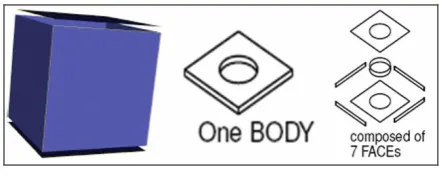
Figure 1. Boundary representation of a 3D model
In this scheme the shapes of faces are defined by underlying surfaces characterized by analytical, parametric equations (e.g. plane, cone, sphere, torus). Similarly, edges are defined as the intersection curves of the surfaces of the adjacent faces. Likewise, vertices define the end point of curves and arise from the intersections of two or more edges.
Consequently, the B-rep is a much richer and more complex data structure than the meshes of planar facets commonly used to define shape in digital animations. However the high degree of interconnections within the data structure means that even small changes have to be made with care. The interdependence inherent in the B-rep data structure is well described by Stroud [10] who says:
“... the shape of an edge cannot be changed without changing the position of the surface, unless the new curve also lies in the surfaces of the faces adjacent to the edge. Similarly the position of vertices can not be changed unless they lie on the curves of all edges meeting at the vertex and hence the vertex position lies on the surfaces of all the faces meeting at the vertex.”
Furthermore, the numerical values used to determine when geometry is coincident (i.e. “on”) also vary greatly. In addition to this inherent sensitivity to change, watermarking also has to cope with the technologies (i.e. IGES, STEP and healing) developed to allow B-rep models to move between different vendor’s CAD systems each with different precisions and formats.
Possible Mechanisms for watermarking B-rep faces
Given these constraints, what methods of watermarking might work for B-reps? The authors considered the following:
Explicit attribute addition: it would be an easy task to associate additional data (i.e. attributes) with the entities of a model and with closed proprietary formats this information would be hard to see or remove. However such information would be lost during system translation, and consequently such a system would be limited in its scope.
Local operation to modify geometry: there is a class of model editing operations known as “local ops” that facilitate small changes on geometry (e.g. offsetting, surface substitution etc.) that could be used to introduce a geometric watermark. However such an approach would not meet the “no change in shape” requirement.
be so small as to be invisible to the naked eye and would not cause any change to the overall shape of the model. However, it could be easily removed by healing operations that detect its redundant nature.
Non-manifold entity addition (flap faces, internal shells, and wire edges): visibly insignificant geometry could be created inside the model. Although this approach is potentially resistant to healing and would not change the external shape, such an approach could still create problems for CNC and RP systems that derive their movement directly from B-rep data. Furthermore, non-manifold geometry can be easily removed by standard modeling utilities.
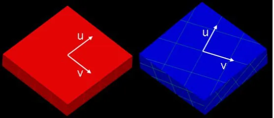
[image:6.595.160.439.296.416.2]Considering these constraints the authors hypothesize that a simple but effective watermark might be possible by altering the orientation of the parametric surfaces underlying B-rep geometry (see Figure 2).
Figure 2. ISO-parameter lines showing surface orientations
All faces (e.g. plane, cylinders, spheres etc.) have a parametric representation that allows them to be traversed in terms of (u, v) coordinates. The orientation of the u-v parameterization is largely determined by the operations used to create the model (i.e. the orientation of bodies united and subtracted to define the shape). The following section describes this approach in more detail and discusses the feasibility of using the orientation of a face’s underlying geometry as a vehicle for watermarking.
5
Method Overview
Despite the complexity of the B-rep data structure many operators (e.g. Booleans, blending, warping) exist which modify a model’s shape while automatically maintaining the integrity of the data structure. One well-known operator, termed a “tweak”, modifies a face’s surface (i.e. its geometry) and then automatically updates its topology (i.e. adjacency relationships) to accommodate the new surface. The key observation underlying the tweaking process is that if a face has been slightly changed (i.e. transformed) in some way, the edges which bound it can be recalculated by: 1. Intersecting the new (i.e. transformed) surface with the surface of each adjacent
intersection, the surface does. This process will define the curves, underlying the edges, which bound the “new” geometry of the face.
2. Intersecting each new curve with its neighbors will determine the bounding vertices of the updated edges.
So it is essential, when a new surface is inserted or modified by rotation of its parametric representation, that the tweaking process automatically intersects it with all the adjacent faces and so recalculates the geometry of the bounding edge’s curves.
5.1 Proposed Scheme
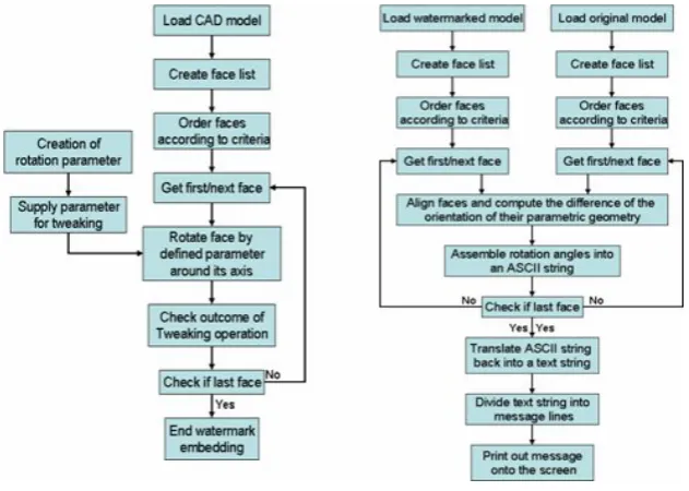
[image:7.595.146.462.418.643.2]Our watermarking scheme, called PO-Watermarking (Parameterization Orientation), is based on tweaking functions which are designed to enable operations such as offsetting or local editing. They also offer opportunities for inserting a watermark by varying the orientation of the underlying parametric surface. In other words, faces with different shapes can be tweaked (i.e. rotated) to change the orientation of their defining surfaces without changing their shapes. Figure 2 illustrates a component before (left) and after (right) all of its faces were rotated about their face normal vectors. To make this change visible the orientation of the u/v axis on one planar face are highlighted with white arrows. We have investigated the feasibility of encoding watermarks by tweaking the surface geometry of individual faces on the model. An overview of the proposed watermarking process is presented in the flowchart below (Figure 3).
Figure 3. Flowcharts of tweaking process (left) and retrieval process (right)
to large. In the case of two or more faces with equal ranking another ordering is carried out which arranges them according to a series of criteria such as the lengths of their circumference and/or the number of edges and lastly the distance of a face centre from a plane defined by the principle axis of inertia. In the case of remaining identical (i.e. equal ranked) faces the first face will be chosen for watermark embedding.
5.2 Fragile watermarking
Having established the number and order of faces to host the watermark, the next step is to determine the angle of each surface rotation, the magnitude of which is in fact the embedded information.
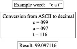
[image:8.595.203.390.339.486.2]The angle for rotation of each face depends on the information to be encoded and its function. When the user enters product, or security, related information into the systems interface (Figure 4) the program arranges the text-information into a single line (text string) and converts it into ASCII code (ASCII string) (Figure 5).
[image:8.595.231.365.574.659.2]Figure 4. Entry of information for embedding
Figure 5. Information conversion and encoding
The ASCII standard defines numerical values, letters and specific characters using numbers between 32 and 127 (e.g. the number 101 is defined to be the letter ”e”). In other words, a triple-digit is required to encode a single letter of the English alphabet. Investigations by the authors have suggested that rotation with up to six decimal places (no rounding influence) can be robustly applied to the model, so each face could potentially encode 3 letters in the following way:
Example word: “c a t”
Conversion from ASCII to decimal c = 099
a = 097 t = 116
Result: 99.097116 Example word: “c a t”
Conversion from ASCII to decimal c = 099
a = 097 t = 116
Result: 99.097116
Embedding procedure
Given a component with N distinctly different (i.e. differing area, shape or relative location) faces, it can hold up to 3N characters in the following way:
1. A list of faces is extracted from the model and ordered by geometric criteria as described above
2. Surface rotation watermark is applied to each face in the ordered list encoding three characters on each face (Figure 6).
This procedure is carried out until the whole information is encoded and embedded into the model. So, the more faces a model has, the more information can be embedded.
Retrieval procedure
The scheme described is a “Private Watermark” meaning that the original CAD model is required to decode the embedded information (Figure 4). This procedure can be summarized as follows:
1. A list of faces is extracted from both original and watermarked models and ordered using the same criteria as for embedding.
2. Faces of equal characteristics (e.g. area, circumferences, etc.) are aligned and the orientation of their parametric geometry computed.
The difference in angle between original and watermarked data (e.g. 28.097218) is broken into three triple-digit numbers (e.g. 028, 097 and 218) and converted back into readable text. This “re-gained” information is then made visible.
5.3 Robust watermarking
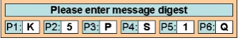
[image:9.595.212.384.548.577.2]The angle of rotation for robust watermarking is created in almost the same way as for fragile watermarking. However, in this case only a short data string such as a message digest (Figure 6) is converted into decimal value (Figure 7). When the code is converted the character’s position (sequence number) is added (e.g. position 1 for K, position 2 for 5, position 3 for P, etc.). This enables the reassembly of the message digest characters when reading out. In this way the watermark on each face contains information analogous to a “packet” number in digital communication protocols.
Figure 6. Entry of message code
Embedding procedure
model is “full”. This would increase the chances that despite modification to the model fractions of the code could be recovered to recreate the message digest.
Figure 7. Message code conversion
Retrieval procedure
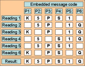
Here again the retrieval process for robust and fragile watermarking are very similar. The faces of the original and the watermarked models are ordered and aligned and the orientation of their parametric geometry is computed. While the fragile watermark is read out once, the robust watermark is retrieved several times (dependent on the size of the CAD file, or up to a user specified limit). In this way we can recover several duplicates of the embedded message code. Should there be any changes to the watermarked model, or if portions of the embedded data got lost (e.g. in translation), it is still possible to recreate the whole message within a few steps. These steps (illustrated in Figure 8) can be summarized as follows:
1. Read out orientation angle of 6 faces (Figure 8 illustrates only 6 faces but obviously this can be extended).
2. Convert orientation value back into readable text.
3. Sort message characters according to their position in the encoded data (recall that the sequence, or packet, number is encoded within the embedding process) and assign them to rows in the message recovery matrix (Figure 8).
4. By identifying common elements in each column of the message recovery matrix reconstruct the original watermark message digest code.
Now this “regained” message digest can be used to verify the correctness of any data or documents associated with the model.
[image:10.595.227.369.529.641.2]Both of these procedures, for fragile and robust watermarking, can be used to embed tracking devices, copyright, product, text, archiving, or any other type of confidential information (e.g. digital signatures to verify associated documents).
6.
Testing and Results
To enable the assessment of the robustness of changed parameterization in mechanical CAD models, a series of test objects were designed in Solid Edge and translated into .sat file format. For these tests a watermark embedder and reader were written in C++ using the V16 of the ACIS kernel modeler.
This program was written to enable the rotation of the underlying parametric surfaces. For the purposes of the investigation the “easily” tweakable planar, closed conical, toroidal and spherical surfaces were modified, those with complex boundaries (i.e. geometry that could create chiralities in the solution) were stepped over at this stage, but will be considered in future embedding and testing procedures.
For further processing the models were imported into ACIS 3DT and healed to accommodate any differences between their originating CAD system’s (i.e. the Parasolid kernel) representation and internal accuracy and ACIS. After embedding a watermark into a model the following series of transformations and modification where undertaken to test the robustness of the PO watermark:
Export/import from SAT file to Solid Edge.
Blending/chamfer of edges with constant radius blend/by 45 degree. IGES export/import: from SAT file into IGES and back into SAT format. STEP export/import: from SAT file into STEP and back into SAT format. Zip compression and decompression of CAD data.
External Boolean subtract: remove the half of the model. Adding new component parts to the model.
After each of these operations the models were translated back into ACIS .sat format and the orientation of the tweakable faces recorded by the PO-watermark reader. The tests have been carried out using arbitrary values of rotation to test the robustness of the proposed PO watermarking scheme. The results are summarized in Table 1 where the second left column records how many faces of each type in the test object were watermarked, while the subsequent columns record how many of these orientations were still readable after each modification.
Although the number of detectable watermarks (recorded in the table) is lower after the Boolean subtraction, it represents a 100% success rate amongst the surfaces not removed or directly involved in the operation (the subtraction operation literally removed half the model). The orientation of the parametric surfaces is also unchanged by blending or chamfer their edges, adding new components to the model, or zip compression.
associated with, or generated by the way in which neutral formats represent the geometry of parametric surfaces. Future work will investigate this behavior.
Table 1. Test results of file conversion and model modification
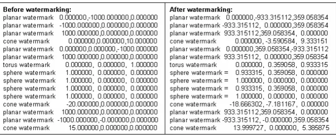
[image:12.595.128.471.191.335.2]Working with native .sat files both embedder and reader displayed a status output onto the screen and also wrote to a text file (Figure 9).
Figure 9. Output of PO-watermark extractor
Figure 9 shows the parametric orientation of the different faces of a test object (Figure 10) before (left) and after (right) watermark embedding with six decimal places containing the embedded information. Faces with zero values for x, y and z coordinates, shown in the left column, contain no information at all. Faces in the right column are carrying the intended message. Here, faces with zero values for their coordinates show that the embedding process was not successful or this particular face was not considered for tweaking.
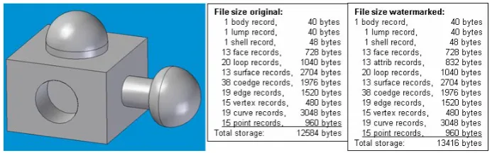
[image:12.595.128.470.368.506.2]Figure 10 shows the PO-watermark did not increase the size of the model data1 and survived file conversion and model modification processes.
Figure 10. Test object with data structure before and after surface tweaking
7.
Discussion
When considering the results, the approach described in this paper meets some of the requirements for 3D-watermarking presented in section two. Regarding file size and transparency, because the PO watermark does not exist in form of “added” data and does not increase the size of the CAD model data, it is difficult to estimate that additional information is hidden within the cover data, even when comparing it with the original unmarked data. Nor has the watermark any influences on the model’s appearance when examined on a CAD system.
The Boolean, chamfer and blending results are understandable: any efficient algorithm will leave geometry not involved in the operation untouched and so it is reasonable to conclude, unless the watermarked surface is removed from the model, its orientation will not be changed. Even adding new components and faces has no influence on the watermark recognition. However, when reading out the watermark after blending and chamfering modification the reader shows sometimes more and sometimes less tweaked faces than actually exist (false positive identification). The authors believe this behavior reflects the process used to create chamfers where parametric orientation is inherited from the adjacent faces during the edge offset stage.
Finally, we can say that despite shape modification and native data export/import and data compression/decompression the watermark has survived and represents a robust characteristic.
However, the face ordering process has a number of negative effects (i.e. limitations). For instance, when ordering faces on a symmetric model it is difficult to identify a suitable or unique face for tweaking because all identical faces have the same characteristics. This leads to the fact that it cannot be guaranteed that exactly the same face is used for tweaking and watermark recovery, which might cause a false
[image:13.595.124.471.175.283.2]
positive detection. Consequently, the face ordering process needs to be based on more sophisticated testing.
It is also surprising to see that IGES and STEP formats have effects on the CAD model. At first thought one might expect the behavior of the IGES and STEP translators to be predictable. The standards define the types of surface entities each can represent and so it should be clear if parametric orientation will be preserved. However there is choice in both which entities a cylinder is mapped to and how the geometry is represented internally within the translation system. Some systems translate all geometric surface entities to NURBS, others hold analytical representations. In many cases the preservation of parametric orientation will be down to a programmer’s whim rather than the specific requirements of Part 42 of ISO 10303 and consequently the behavior can only be determined experimentally. Therefore, the behavior of PO-watermarks in translation to STEP/IGES is an area of further study for the authors.
Compared to other established watermarking algorithms for polygonal meshes or NURBS, our PO-watermarking scheme based on B-reps opens new ways/possibilities to hide information robustly into mechanical CAD data. For instance, Ohbuchi’s method [1] could only be applied to B-spline surfaces and could not be used (unlike the PO-Watermark method) to watermark analytical surfaces like planes, cylinders and other face types, which are very common in mechanical CAD systems.
8.
Conclusion
The PO-watermark appears to offer a simple and effective way of identifying and tracking B-rep models within a homogenous industrial CAD/CAM environment (i.e. one supplier, no translation). Additionally, this method can also be used for identifying the licensee or to prove ownership in dispute by showing a robust attribute to modification. The amount and uniformity of the surface rotation within a model can be varied to encode information in a manner analogous to the vertex moving watermarks applied to mesh models. However, the approach must be considered fragile at this stage as the combination of STEP and IGES translation is able to “wash” the watermark out of the model.
Future work will investigate translation issues and the magnitude limits of PO watermarking: what is the smallest and largest change in orientation that can be robustly recorded?
Compression/decompression of watermarked data with different systems (e.g. Adobe 3D) and the enlargement of this approach to achieve a public watermark are also areas of interest to the authors.
References
Workshop on Knowledge Intensive CAD to Knowledge Intensive Engineering, Deventer, The Netherlands, (2000), pp. 103-116.
[2] C. Chou and D. Tseng, "A public fragile watermarking scheme for 3D model authentication," Computer -Aided Design 2006, Vol. 38, (2006), pp. 1154-1165.
[3] R. Ohbuchi, H. Masuda, and M. Aono, "Watermarking Three-Dimensional Polygonal Models," presented at ACM International Multimedia Conference ’97, Seattle, Washington, USA, November 9-13, (1997), pp. 261-272. [4] R. Ohbuchi, A. Mukaiyama, and S. Takahashi, "A Frequency-Domain
Approach to Watermarking 3D Shapes," EUROGRAPHICS 2002, Vol. 21, No. 3, (2002), pp. 373-382.
[5] M. Corsini, M. Barni, F. Bartolini, R. Caldelli, V. Cappellini, and A. Piva, "Towards 3D watermarking technology," presented at IEEE EUROCON 2003 Conference, 22-24 September, Ljubljana, Slovenia, (2003), pp. 393-396.
[6] Z. Rušinović and Ž. Mihajlović, "Robust Watermarking for 3D Objects,"
presented at MIPRO 2005: Hypermedia and GRID systems, 30 May-3 June, Opatija, Croatia, (2005), pp. 271-276.
[7] O. Benedens, "Geometry-Based Watermarking of 3D Models," IEEE Computer Graphics and Applications, January/February 1999, (1999), pp. 46-55.
[8] E. Praun, H. Hoppe, and A. Finkelstein, "Robust Mesh Watermarking," presented at International Conference on Computer Graphics and Interactive Techniques, August, (1999), pp. 49-56.
[9] H. Sonnet and S. Lange, "Data Storage: Carrier Objects as Illustration Watermarks for 3D Polygonal Models," presented at Simulation und Visualisierung, March 2005, (2005), pp. 305-316.