50th 3AF International Conference on Applied Aerodynamics
29-30 March – 01 April 2015, Toulouse - France
FP18-2015-martin
A MULTI-POINT PERFORMANCE MATCHED AEROFOIL DESIGN ALGORITHM FOR A
SCALED WIND TURBINE ROTOR MODEL
S. Martin (1), A. H. Day (1)
(1)
University of Strathclyde, 204 George Street, Glasgow, G1 1XW, United Kingdom, Email:[email protected]
ABSTRACT
A search-based multi-point aerofoil design algorithm is presented which optimises a profile for a prescribed CL-α distribution and Reynolds number, Re. A real-coded genetic algorithm is used in conjunction with XFOIL and a geometrically constrained shape parameterisation method to produce smooth, manufacturable aerofoils given the required aerodynamic performance.
The validated tool is used to produce a family of aerofoils to define a model rotor blade for a wind turbine with a similar axial induction factor along its length in a small scale laboratory environment to a full scale reference. It is hypothesised that given the similar axial induction and similar non-dimensional geometry, the model rotor will have a similar unsteady aerodynamic response to the full scale.
1. INTRODUCTION
In order to develop a better understanding of the relatively poorly comprehended unsteady aerodynamic response of wind turbine rotors (WTR) it would be beneficial to conduct a series of small scale experiments as would be typical of a complex fluid flow problem. However, for the particular case of a WTR, the three traditional scaling rules, geometric, kinematic, and dynamic similarity cannot be maintained simultaneously in a typical small scale laboratory environment [2]. As a result, rather than the achievement of similar flow, the traditional design of small scale WTR models is based on attaining stable, attached flow at the
experimental Reynolds number. No attempt is typically made to attain geometric similarity, however kinematic similarity is readily achieved by ensuring the range of tip-speed ratios (TSR) at which the model rotor will operate is analogous to a full scale reference. Dynamic similarity is not maintained due to the resulting blade chord Reynolds number deficit [3].
In order to address the scaling difficulties discussed, a number of global performance matching solutions have been proposed where the primary design objective is to reproduce the rotor thrust at model scale to act as an input into a more complex system. This has particularly been applied to the assessment of the motion of a floating wind turbine system (FWTS) in a scaled wind and wave environment [4,5]. The rotor is designed such that the coefficient of thrust is similar to that of the full scale reference at corresponding TSRs, in the case of the FWTS model this allows for the dominant overturning moment to be replicated. The manner in which the global thrust coefficient is generated is unspecific as the local blade aerodynamic response in not performance matched. As a result, it is not possible to assess the aerodynamic response of a full scale reference based on data collected from such a model.
have a similar non-dimensional lift force, over a range of angles of attack at the experimental Reynolds number, as the reference operating in a full scale environment. In doing so the full scale non-dimensional chord and twist distribution can be maintained at model scale and a similar axial and tangential induction achieved. Achieving this maximises the similitude of the unsteady response of the model rotor to the reference as the primary excitation frequencies of the dominant contributors are a function of the flow velocity over the blade, axial induction, blade chord distribution, and rotor radius [6,7], all of which is maintained non-dimensionally between scales.
This paper outlines the aerofoil design methodology developed in order to achieve the similar lift performance criteria required for the discussed model design to be accomplished. This will focus on the steady response of the model rotor, particularly the achievement of a similar axial induction factor along the blade which will result in a local and global non-dimensional thrust force similar to a reference.
2. SCALING METHODOLOGY
The primary objective of the model rotor design process is to ensure that the non-dimensional thrust force, CT, at model scale is similar to that at full scale for a range of TSRs, λ, as shown in Eq. 1. It would be desirable to achieve a similar degree of similitude for the rotor coefficient of torque, however as a result of the increased drag at the lower experimental Reynolds number [8] and the relative contribution of the aerofoil lift and drag forces to the global rotor loading this will not be possible.
(1)
If the unsteady aerodynamic thrust response is to be considered similar to the reference at model scale, Eq. 2 will also have to be satisfied.
(2)
If the classical stiff scaling approach, the retention of geometric, kinematic, and dynamic similarity [2], were achievable at model scale for a WTR, Eqs. 1 and 2 would automatically be satisfied. However, this is not possible and as such it is necessary to implement the aforementioned performance matching methodology [4,5]. Typically, the global
focus of the techniques described in the literature do not allow for the unsteady response of the rotor to be studied as the load generation is not similar along the length of the blade. As it is necessary to be able to accurately predict the performance of the rotor in the state for which it will be matched, performance matching a model rotor's unsteady response is difficult due to the limitations and uncertainties of current unsteady wind turbine rotor performance numerical prediction algorithms [1].
In order to incorporate the consideration of a rotor's unsteady aerodynamic response into the performance matching methodology, it is proposed that surrogate similarity criteria are met which allow for the retention of the non-dimensional blade chord and twist distribution at model scale and a similar axial induction factor along the length of the blade. The primary objective will be that the blade profile be re-designed such that each of the distinct 2-dimensional aerofoil profiles which define it have a similar non-dimensional lift force over a range of angles of attack at model scale to the full scale reference. Doing so effectively corrects for the Reynolds number dissimilitude induced change in the lift force by altering the geometry of the profile, this is defined in Eq. 3.
(3)
Eq. 3 should be satisfied for multiple angles of attack prior to trailing edge separation, this allows for the model rotor to be representative of the full scale reference at multiple TSRs. This requires that a multi-point aerofoil design algorithm be used to design a series of aerofoils from which a smooth blade design can be developed.
3. MULTI-POINT AEROFOIL DESIGN REVIEW
In order for the scaling methodology described in Section 2. to be realised, a series of aerofoils will have to be designed which have the same non-dimensional lift force at multiple angles of attack at the experimental Reynolds number as the full scale reference profiles. Although a number of multi-point aerofoil design tools have been proposed in the literature, none of these specifically address the design of profiles to have specific lift performance at a number of angles of attack. However, in many cases the techniques applied in the literature are applicable to the current problem with the objective function re-written to reflect it.
multi-point problem the direct approach dominates, although Selig and Maughmer [9] did propose an early generalised inverse method based on Eppler's theory and conformal mapping. Direct methodologies involve iterating on the parameterised aerofoil shape informed by the evaluation of an objective function, these can be further categorised as being gradient-based and search-based. Examples of each of these will be subsequently discussed and used to inform the development of a design tool for the current problem.
Gradient-based aerofoil shape optimisation approaches generally iterate on the profile in the vicinity of a seed individual directed by the polarity of the derivative of the objective function solution with respect to the design variables. The objective functions are generally defined by a weighted sum formula of the flow properties of interest at multiple operating points. Difficulties arise when assigning weights to each operational component of the objective function as this inherently directs the solution towards a particular operational point; an unbalanced objective function will result in an unbalanced solution [10]. The operational points at which the shape optimisation procedures are conducted using a gradient-based approach are generally defined in terms of different Mach numbers as the solutions are based on an aircraft's operational environment. It was proposed by Drela [11], mathematically proven by Li et al [12], and empirically confirmed by Buckley et al [13] that the number of operational points considered must be greater than the number of design variables used to define the individual aerofoil for a smooth solution to be produced.
Nemec et al [10] detail a gradient based aerofoil shape optimisation algorithm capable of solving multi-point and multi-objective problems. This is validated by optimising the RAE 2820 aerofoil for reduced drag for a single corresponding coefficient of lift at four different Mach numbers. The reduction of drag at each operating point is adequate, both in terms of the value achieved and the satisfaction of the lift coefficient constraint, however the optimised shape produced could not be physically implemented as a result of its undulating surface. An adaptive, weighted-sum, gradient-based, unconstrained aerofoil profile optimisation algorithm for a full range of typical aircraft operating conditions is described by Buckley et al [13]. The weights applied to the off-design points, in this case different Mach numbers, are altered given their perceived respective influence on the optimal design as the algorithm
progresses. As a result of the large number of operational points considered, the optimised aerofoil has a smooth profile and could be physically used.
Aerofoil profile optimisation based on search-based approaches are generally more robust than the gradient based alternative, however this is at the cost of significantly decreased computation efficiency. The solution space is searched based on the biological theory of natural section, from an initial random population, operators such as selection, crossover, and mutation develop the next generation from the previous such that the proceeding has a mean fitness to the objective function greater than the preceding. This process is conducted iteratively until the global optimum solution is found [14]. The common example of such an approach, upon which the majority of the literature is based, is the genetic algorithm (GA).
Search-based optimisation algorithms will more readily converge onto a global, rather than local optimum individual as the whole solution space is sampled as part of the process. As a result, in cases where the problem is set such that the solution will not readily be found in the vicinity of a seed profile, i.e. drag reduction for a given lift coefficient as is the case for Nemec et al [10], a search-based approach would be more suitable [15].
also been described by Bizzarrini et al [18] and Ribeiro et al [19].
None of the discussed aerofoil shape optimisation procedures specifically address the requirement of the lift specific multi-point design problem. However, in building a bespoke solution it is clear that a number of the individual techniques and procedures used can inform the development of the tool. The weighted-sum objective function definition preferred by the majority of studies discussed is based on the notion that there is one on-design point and a series of off-design points, however in this case all operating points are as equally important to the design requirement. An objective function definition will have to be developed which accounts for the equal weighting and treatment of the polarity of the difference of an individual to the objective. The multi-point lift specific aerofoil design algorithm will have a large solution space which indicates that a search-based optimisation approach should be taken. This will allow for a global optimum solution to be considered rather than the potentially local optimum in the vicinity of a seed profile if a gradient-based approach were to be used [15].
4. MULTI-POINT AEROFOIL DESIGN ALGORITHM
Given the potentially large and disparate solution space, the proposed multi-point aerofoil design algorithm will be search-based. A real-coded, simple, GA will be used to ensure maximum robustness and adaptability. The objective function will be defined in terms of the lift coefficient at three different angles of attack prior to stall at the experimental Reynolds number and the corresponding coefficient of lift of the full scale aerofoil. The assumed linearity of this section and the criteria of an exact solution enforcing this ensures that this procedure will not suffer from the non-smooth solution issues discussed by Drela [11], Li et al [12], and Buckley et al [13]. This can be further addressed by the use of an aerofoil parameterisation methodology which is designed and bounded to ensure the production of smooth profiles.
The following sections will detail each of the components of the multi-point aerofoil design algorithm followed by a validation of the procedure.
4.1. Aerofoil Parameterisation
It is necessary to parameterise the aerofoil geometry in order to reduce the number of design variables such that the computational time is
acceptable. A number of schemes have been proposed in the literature, all of which attempt to describe the shape of the upper and lower surface of an aerofoil using less variables than explicitly listing a series of coordinate points. These can generally be categorised into two groups; those which define the aerofoil profile in terms of physical variables, i.e. nose radius, trail edge angle, etc. [20], and those which don't [21]. Although defining the profile in terms of physical properties is advantageous for the evaluation of geometric constraints, the potential exists for such a definition to be limited by the design variables and the range in which they exist [19].
In this case, a parameterisation methodology has been devised which allows for a mix of physical and non-physical parameters to define the aerofoil geometry. This is defined for each surface, S, by Eq. 4. A symmetrical base aerofoil, y/c|base,S, is defined in terms of the non-dimensional thickness,
t, characterised by the NACA 4-series equation. This function should be multiplied by -1.0 if the surface being considered, S, is the lower.
(4)
A degree of camber is applied to the base shape using a third order sinusoidal function as defined in Eqs. 5 and 6, the degree, γcam, and position, xcam, of the maximum point on the function is constrained by setting bounds of allowable values.
(5)
(6)
The cambered base shape is separated into upper and lower surfaces and distinct functions created to modify each surface, Δy/c|S, by a j
th
order Hicks-Henne function after Deng and Qiao [22] as defined in Eqs. 7-9. The magnitude of each function is defined by a vector, bS, of length j and its position relative to the non-dimensional aerofoil chord in each case by xS,k. The magnitude, bS, is the primary design variable operated on by the optimisation algorithm and is strictly bounded to constrain each individual.
(8)
(9)
By defining the surface modification in terms of product of the base function rather than the sum, the change in the surface thickness is more readily controlled as it is a function of the base aerofoil thickness. The base aerofoil thickness, magnitude and position of the degree of camber, and the two 11th order Hicks-Henne surface modification amplitude vectors are the optimisation design variables.
4.2. Initial Population Definition
The initial population is defined stochastically by generating Gaussian random real number for each of the design variables between predefined bounds. These bounds are empirically derived during the GA tuning process such that the area of the feasible solution region accounted for is maximised.
4.3. Selection, Crossover, and Mutation
Individual selection for the next generation is conducted using a weighted roulette wheel scheme. This works to ensure that the individuals with the highest fitness are more readily selected for mating operators, this is traditionally used in simple, single objective GA optimisation schemes [14]. The primary real number coded GA operators are typically individual crossover and mutation, there are numerous methods for conducting each [23]. In this case the simulated binary crossover [24] and a general Gaussian mutation [25] operators are utilised.
4.4. Objective Function Evaluation
In order to determine the value of the fitness of each individual such that selection of the next generation can take place, the aerodynamic performance of the aerofoil has to be determined. In this case XFOIL, a 2-dimensional panel method, will be used to determine the coefficient of lift at the operating points considered [26]. Ram et al [16] validate the use of XFOIL for the calculation of lift and drag coefficients at a Reynolds number of
2x10⁵ with and without leading edge trips against
experimental data. The analysis in this case is conducted at a Reynolds number of 1E5 which is typical of a representative experimental environment and that for which XFOIL has been validated. The flow transition at the leading edge will be forced on both the upper and lower surfaces to remove any adverse laminar separation effects.
The objective function is defined in a similar manner to that described by Nemec et al [10], however in this case no drag term is included. Equal weights are applied to each operational point as each can be considered as equally important for the match of the lift to the reference aerofoil. Eq. 10 defines the objective function for m
operational points, the least squares sum is used such that no preferential treatment is given to individuals with a positive objective function value.
(10)
4.5. Constraint Handling
Generally, GA constraint management techniques work to penalise the fitness values for invalid individuals such that the probability of selection to the next generation is minimised. However, in this case this would be an inefficient method as a result of the computational expensive and potentially unstable objective function. It is advantageous to define the structure of the GA such that only individuals for which XFOIL can conduct a flow analysis for are selected, therefore the death penalty constraint handling technique is used. This removes any invalid individual from the population and replaces it through the selection process [27].
The definition of the aerofoil parameterisation variable bounds are also used to explicitly constrain the problem geometrically. A minimum allowable non-dimensional thickness and maximum position and degree of camber can be defined in accordance with the manufacturing constraints for the model scale wind turbine blade. In discussing their previous work on the subject, Reuther et al [28] describe a similar method for shape parameterisation level constraint handling.
4.6. Elitism and Niching
values to identify the elite points; this can be generally referred to as creating a gene pool [17].
In order to ensure that a diverse population is maintained throughout the generations niching techniques are used to maintain individuals in the population which would otherwise be lost as part of the natural selection process. Population diversity control is especially necessary in multi-modal optimisation problems [30] which it has been shown by Khurana and Winarto [31] that aerofoil shape optimisation problems are. In this case an innovative approach based on n-dimensional spherical coordinates is taken to account for the high dimensionality of the problem.
Each individual, i, in a given generation, g, has a fitness value F which is a function of n design variables as shown in Eq. 11. If it is assumed that the fitness of each individual is a vector distance from the optimal point, 0.0, and the design variables the component distances in each plane which resolve to the orthogonal distance, n-1
angles, φ, can be determined which define the position of F in the n-dimensional search space. The first n-2 angles will exist in the set [0,π/2], the final φn-1 in the set [0,π], if each individual is assigned a bin within the angle set for each dimension, the dispersion of the individuals in the
n-dimensional region can be discretely determined. The non-dominated individual in each bin can then be added to the elitist gene pool, with duplicate individuals removed, to be passed to the next generation. This hyper-niching algorithm ensures that a similar degree of population diversity exists in the last generation as it does in the first.
(11)
In addition to the hyper-niching algorithm, diversity is maintained between generations by running each population in segments parallel and independent from one another. Two classes of individuals are created, superior and inferior, which contain individuals grouped by their fitness value. The one superior population operates like a regular GA, the multiple inferior populations only work within themselves with small populations of lesser individuals to add value to the superior population and maintain diversity in the population as a whole. Individuals are chosen to mate for the next generation from the respective segments probabilistically.
4.7. Evaluation
The presented lift specific multi-point aerofoil algorithm is validated by producing an aerofoil design which has a similar CL-α curve as the
NACA 64618 profile at a Reynolds number of
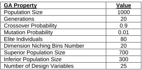
1.0x10⁵. The full scale reference data was collected during wind tunnel tests at a Reynolds number of 6.0x10⁶ by Kooijman et al [32]. The optimisation algorithms parameters are determined from an empirical tuning process which systematically altered the controlling parameters to find the optimum settings [33], these are detailed in Tab 1. The aerodynamic properties are detailed in Tab. 2.
Table 1: GA Optimisation Parameters
GA Property Value
Population Size 1000
Generations 20
Crossover Probability 0.9 Mutation Probability 0.01
Elite Individuals 80
Dimension Niching Bins Number 20 Superior Population Size 700 Inferior Population Size 300 Number of Design Variables 25
Table 2: Aerodynamic Optimisation Parameters
Aerodynamic Property Value
Reynolds Number 1.0x10⁵
Design Angles of Attack
2°
5°
9°
Target Lift Coefficients
0.670 1.011 1.335
[image:6.595.311.540.268.381.2]Figure 1: NACA 64618 Experimental Reynolds Number Performance Matched Aerofoil
4.8. Aerofoil Family Determination
To complete the model scale blade design a family of aerofoils will have to be designed for the experimental Reynolds number which have a similar lift performance to each of the aerofoils which define the full scale reference blade. The model scale family should geometrically blend into one another to avoid the induction of any unnecessary 3-dimensional aerodynamic effects and to aid the manufacturing of the blade. This is achieved by reducing the dimensionality of the problem by limiting the geometric alterations which can be made from the base aerofoil, which in this case is the profile which precedes it on the blade from the tip, rather than the symmetrical NACA profile in the first instance. The application of these further shape parameterisation level constraints ensures that the leading- and trailing-edge geometries are consistent throughout the entire family.
5. ROTOR DESIGN EVALUATION
The full scale reference wind turbine on which the design of the model scale rotor is based is the NREL 5MW Baseline Wind Turbine [34], this was chosen due the publicly available specification and its wide spread use in the literature. The blade of this rotor is defined from six distinct aerofoil profiles, for each of which a model scale profile will have to be designed to replicate its non-dimensional lift performance. Full scale wind tunnel data exists for each of the reference profiles [32],
[image:7.595.314.534.297.620.2]this is used to define the reference objective values. The outer most aerofoil on the NREL blade is the NACA 64618 profile studied in Section 4.7, the result from this analysis will be used for the model rotor design. The proceeding five model scale profiles are iterated from this given the appropriate lift performance objectives. Fig. 2 shows the model scale aerofoil family determined using the multi-point aerofoil design algorithm. The consistent leading- and trailing-edge geometries and smooth transitions at the main body of the profiles ensure that the blade is readily manufacturable. The aerodynamic performance of each of the aerofoils is a good match to the full scale reference. Fig. 3 shows the comparison of the full and model scale aerofoils of the inner most blade profile, DU99-W-405. A comparable match of the non-dimensional lift force is achieved for each of the remaining profiles.
Figure 2: Model Scale Aerofoil Family
Figure 3: DU99-W-405 Experimental Reynolds Number Performance Matched Aerofoil
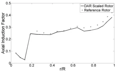
scale rotors along the length of the blade for a TSR of 7. Defining the model rotor blade with lift specific designed aerofoil allows for a good match between the model and full scale axial induction factors to be achieved which allows for a similar non-dimensional thrust to be generated by the whole rotor.
Figure 4: Axial Induction Factor Non-dimensionally Along the Blade Comparison of Model and
Reference Rotors, TSR = 7
6. CONCLUSIONS
A multi-point aerofoil shape optimisation algorithm has been presented for the design of performance matched model scale wind turbine rotors. This uses a real-coded GA, a constraint integrated shape parameterisation method, and XFOIL to produce smooth aerofoil geometries which have a specified non-dimensional lift, at multiple angles of attack for a particular Reynolds number. This has been validated against wind tunnel data for the
NACA 64618 aerofoil profile, the outer most profile of the NREL 5MW reference rotor blade.
A family of model scale aerofoils is produced using a version of the aerofoil design tool with a reduced number of variables. The six model scale aerofoils presented are used to define the cross-section of a model scale rotor blade which has been shown to have a similar axial induction factor as the full scale blade at the same TSR.
7. ACKNOWLEDGEMENTS
This work has been funded by the EPSRC, project reference number EP/G037728/1, and further supported by Lloyd’s Register. The views expressed are those of the author alone and do not necessarily represent those of Lloyd’s Register.
8. REFERENCES
[1] Leishman, J. G. (2002). Challenges in Modelling the Unsteady Aerodynamics of
Wind Turbines. Wind Energy, 5(2-3), 85-132.
[2] Haans, W. (2011). Wind Turbine Aerodynamics in Yaw: Unravelling the measured rotor wake. PhD Thesis, Technische Universiteit Delft: Netherlands. [3] Vermeer, L. J., Sørensen, J. N., and
Crespo, A. (2003). Wind turbine wake aerodynamics, Progress in aerospace sciences, 39(6), 467–510.
[4] Martin, H. R., Kimball, R. W., Viselli, A. M., & Goupee, A. J. (2014). Methodology for Wind/Wave Basin Testing of Floating Offshore Wind Turbines. Journal of
Offshore Mechanics and Arctic
Engineering, 136(2): 020905.
[5] de Ridder, E. J., Otto, W., Zondervan, G.-J., Huijs, F., & Vaz, G. (2014). Development of a Scaled-Down Floating Wind Turbine for Offshore Basin Testing. In: Proceedings of the ASME 2014 33rd International Conference on Ocean, Offshore and Arctic Engineering, San Francisco, CA. American Society of Mechanical Engineers.
[6] de Vaal, J. B., Hansen, M. O. L., & Moan, T. (2012). Effect of wind turbine surge motion on rotor thrust and induced velocity.
Wind Energy, 17(1), 105-121.
[7] Larsen, J. W., Nielsen, S. R. K., & Krenk, S. (2007). Dynamic stall model for wind turbine airfoils. Journal of Fluids and Structures, 23(7), 959–982.
[8] Freudenreich, K., Kaiser, K., Schaffarczyk, A. P., Winkler, H., & Stahl, B. (2004). Reynolds Number and Roughness Effects on Thick Airfoils for Wind Turbines. Wind Engineering, 28(5), 529–546.
[9] Selig, M. S., & Maughmert, M. D. (1992). Generalized Multipoint Inverse Airfoil Design. AIAA Journal, 30(11), 2618-2625. [10] Nemec, M., Zingg, D. W., and Pulliam, T.
H. (2004), Multi-Point and Multi-Objective Aerodynamic Shape Optimization. AIAA journal, 42(6), 1057-1065.
[11] Drela, M. (1998). Pros and Cons of Airfoil Optimization. In: Frontiers of Computational Fluid Dynamics.
[12] Li, W., Huyse, L., and Padula, S. (2001)
Robust Airfoil Optimization to Achieve Consistent Drag Reduction Over a Mach Range, Tech. Rep. ICASE-TR-2001-22, Institute for Computer Applications in Science and Engineering, Hampton, Virginia.
Practical Aerodynamic Design Requirements. Journal of Aircraft, 47(5), 1707–1719.
[14] Goldberg, D. E. (1989). Genetic Algorithms in Search, Optimization, and Machine Learning, Addison-Wesley, Reading, Massachusetts.
[15] Zingg, D. W., Nemec, M., and Pulliam, T. H. (2008). A comparative evaluation of genetic and gradient-based algorithms applied to aerodynamic optimization,
European Journal of Computational
Mechanics/Revue Européenne de
Mécanique Numérique, 17(1–2), 103–126.
[16] Ram, K. R., Lal, S., and Rafiuddin Ahmed, M. (2013). Low Reynolds number airfoil optimization for wind turbine applications using genetic algorithm, Journal of Renewable and Sustainable Energy, 5(5), 052007.
[17] Ju, Y. P., & Zhang, C. H. (2011). Multi-point robust design optimization of wind turbine airfoil under geometric uncertainty.
Proceedings of the Institution of Mechanical Engineers, Part A: Journal of Power and Energy, 226(2), 245–261.
[18] Ribeiro, A. F. P., Awruch, A. M., and Gomes, H. M. (2012). An airfoil optimization technique for wind turbines, Applied Mathematical Modelling, 36(10), 4898-4907.
[19] Bizzarrini, N., Grasso, F., & Coiro, D. P. (2011). Genetic algorithms in wind turbine airfoil design. In: EWEA2011, Brussels,
Belgium. European Wind Energy
Association.
[20] Sobieczky, H. (1999). Parametric airfoils and wings. In: Recent Development of Aerodynamic Design Methodologies (pp. 71-87). Vieweg+ Teubner Verlag.
[21] Kulfan, B. M. (2008). Universal Parametric Geometry Representation Method. Journal of Aircraft, 45(1), 142–158.
[22] Deng, L., & Qiao, Z. D. (2010). A Multi-Point Inverse Design Approach of Natural Laminar Flow Airfoils. In: 27th International Congress of the Aeronautical Sciences. Nice, France. International Council of the Aeronautical Sciences.
[23] Yoon, Y., & Kim, Y. (2012). The Roles of Crossover and Mutation in Real-Coded Genetic Algorithms. In: Bio-Inspired Computational Algorithms and Their
Applications. INTECH Open Access
Publisher.
[24] Deb, K., & Agrawal, R. B. (1995). Simulated Binary Crossover for
Continuous Search Space. Complex Systems, 9(3), 115–148.
[25] Herrera, F., Lozano, M., & Verdegay, J. L. (1998). Tackling Real-Coded Genetic Algorithms: Operators and Tools for Behavioural Analysis. Artificial Intelligence Review, 12(4), 265–319.
[26] Drela, M. (1989). XFOIL - An Analysis and Design System for Low Reynolds Number Aerofoils. In: Conference on Low Reynolds
Number Aerodynamics (Vol. 54).
University of Notre Dame, Indiana.
[27] Coello, C. A. C., & Carlos, A. (1999). A survey of constraint handling techniques used with evolutionary algorithms. Tech. Rep. Lania-RI-99-04, Laboratorio Nacional de Informática Avanzada, Mexico.
[28] Reuther, J. J., Jameson, A., Alonso, J. J., Rimlinger, M. J., and Saunders, D. (1999). Constrained Multipoint Aerodynamic Shape Optimization Using an Adjoint Formulation and Parallel Computers, Part 1, Journal of Aircraft, 36(1), 51–60.
[29] Marler, R. T., & Arora, J. S. (2004). Survey of multi-objective optimization methods for engineering. Structural and Multidisciplinary Optimization, 26(6), 369– 395.
[30] Hall, M. (2012). A Cumulative Multi-Niching Genetic Algorithm for Multimodal Function Optimization. International Journal of
Advanced Research in Artificial
Intelligence, 1(9), 6–13.
[31] Khurana, M., & Winarto, H. (2010). Development and validation of an efficient direct numerical optimisation approach for aerofoil shape design. The Aeronautical Journal, 114(1160), 611.
[32] Kooijman, H. J. T., Lindenburg, C., Winkelaar, D., & van der Hooft, E. L. (2003). DOWEC 6 MW Pre-Design: Aero-elastic modelling of the DOWEC 6 MW pre-design in PHATAS. Netherlands, Tech. Rep. DOWEC-F1W2-HJK-01-046/9, ECN, Petten, Netherlands.
[33] Gardner, B. A., & Selig, M. S. (2003). Airfoil Design Using a Genetic Algorithm and an Inverse Method. In: 41st Aerospace Sciences Meeting and Exhibit, Reno, Nevada. American Institute of Aeronautics and Astronautics.
[34] Jonkman, J., Butterfield, S., Musial, W., & Scott, G. (2009). Definition of a 5-MW Reference Wind Turbine for Offshore
System Development. Tech. Rep.
[35] Ning, S. A. (2014). A simple solution method for the blade element momentum
equations with guaranteed