City, University of London Institutional Repository
Citation
:
Cooke, G.M.E. (1987). The structural response of steel I-section members subjected to elevated temperature gradients across the section. (Unpublished Doctoral thesis, City University London)This is the accepted version of the paper.
This version of the publication may differ from the final published
version.
Permanent repository link:
http://openaccess.city.ac.uk/8337/Link to published version
:
Copyright and reuse:
City Research Online aims to make research
outputs of City, University of London available to a wider audience.
Copyright and Moral Rights remain with the author(s) and/or copyright
holders. URLs from City Research Online may be freely distributed and
linked to.
City Research Online: http://openaccess.city.ac.uk/ [email protected]
THE STRUCTURAL RESPONSE OF STEEL I-SECTION MEMBERS SUBJECTED
TO ELEVATED TEMPERATURE GRADIENTS ACROSS THE SECTION
by
Gordon Michael Eyre Cooke, BSc, CEng, MIMechE, MICE, FIFireE.
A thesis submitted in partial fulfilment of the requirement
for the Award of Degree of Doctor of Philosophy
in Civil Engineering (structures)
Department of Civil Engineering
The City University
London
TABLE OF CONTENTS
Page
Title page I
Table of contents 2
List of tables 9
List of illustrations 16
Acknowledgements 30
Abstract 31
Notation 32
CHAPTER 1. INTRODUCTION 33
1.1 Building regulations and codes of practice 33
1.2 Meaning of fire resistance 36
1.3 Optimising the fire resistance of structural steel 38
1.14 Fire engineering analyses '10
1 .5 The concept of limiting temperature Ill
1.6 Temperature gradients and thermal bowing 1414
1 .7 Research on steel beams having temperature
gradients across the section 146
1 .8 Research on steel columns having temperature
gradients across the section 118
1.9 Objectives and scope of research 514
1.9.1 Objectives of research 55
1.9.2 Scope of research 57
CHAPTER 2. STEEL PROPERTIES AT ELEVATED TEMPERATURES 60
2.1 Introduction 60
2.2 Poisson's ratio 60
2.2.1 General 60
Page
2.3
Thermal expansion and phase transformation62
2.3.1
General62
2.3.2
Coefficient of linear expansion62
2.3.3
Variation of thermal expansion with temperatureand phase transformation
63
2.4 Elastic-plastic behaviour
66
2.k.1 Stress-strain at room temperature
66
2.4.2 Stress-strain at elevated temperatures
67
2.4.3 Anomalies In elastic modulus data at elevated
temperatures
68
2.4.4 Review of elevated temperature stress-strain data
71
2. 1L5 Significance of differences in elastic modulus at
elevated temperatures
76
2.'I.6 Idealised stress-strain data at elevated
temperatures
77
2.4.7
Limiting plastic strain78
CHAPTER
3.
THEORY OF UNRESTRAINED THERMAL BOWING OF A MEMBER80
3.1 Assumptions
80
3.2 Displacements of a non-loaded, simply supported member
having a linear temperature profile across its section
which does not vary with length
81
3.3
Displacements of a non-loaded, cantlievered memberhaving a linear temperature profile across its section
which does not vary with length 83
3.4 Displacements of a non-loaded, simply supported member
comprising 4 finite lengths, each having a different
Page
3.5 Displacements of a non-loaded, simply supported member
comprising many finite lengths, each having a different
linear temperature profile across its section 88
3.6 Effect of variable elastic modulus on unrestrained
thermal bowing 90
CHAPTER 11. EXPERIMENTS ON UNRESTRAINED BEAMS AND COLUMNS
HEATED ALONG ONE FLANGE 91
ILl Experiments on an unrestrained model beam 91
11.1.1 Test apparatus 92
11.1.2 Test specimen and thermocouples 95
11.1.3 Test procedure 96
4.1.4 Test results 97
11.1.5 Comments on test results 97
11.2 Theory of unrestrained thermal bowing applied.to
unrestrained model beam experiments 99
11.2.1 Central displacement, whole flange heated 99
11.2.2 Central displacement, half flange heated 100
11.3 Comparison of theory and experiment for unrestrained
model beam 102
11.3.1 Central displacement, whole flange heated 102
11.3.2 Central displacement, half flange heated 103
14.11 Finite element analyses for unrestrained model beam
experiments loll
11.11.1 Introduction 1011
11.11.2 Summary of experimental data used in analyses 105
11. 11.3 Derivation of equivalent parallel flange
Page
11.11. 11 Element mesh models used in PAFEC analyses 106
11. 14.5 Analyses, whole flange heated 107
'I.'l.6 Comparison of analyses and experiments, whole
flange heated 109
11. 11.7 Analyses, half flange heated 111
11. 14.8 Comparison of analyses and experiments, half
flange heated 113
11.5 Full scale experiments for unrestrained thermal bowing
of a column 1111
11.5.1 Introduction 1111
$.5.2 Experimental arrangement 115
11.5.3 Analysis of results 116
11.6 Conclusions 117
11.6.1 Conclusions from unrestrained model beam
experiments 117
11.6.2 Conclusions from unrestrained full scale
column experiments 119
CHAPTER 5. EXPERIMENTS ON RESTRAINED MODEL 2-SPAN CONTINUOUS
BEAM HEATED ALONG ONE FLANGE 121
5.1 Introduction 121
5.2 Elastic theory for calculating the restraint force 124
5.3 Experiments 125
5.3.1 Details of model test beam and thermocouples 125
5.3.2 Chemical composition and mechanical properties 125
5.3.3 Apparatus 126
5.3.14 Experimental procedure 128
Page
5.14 Elastic theory applied to experiment 132
5.5 Comparison of elastic theory and experiment 134
5.6 Conclusions 134
CHAPTER 6. EXPERIMENTS ON DESIGN-LOADED MODEL BEAM HEATED
ALONG ONE FLANGE 137
6.1 Design of experiment 137
6.2 Fabrication of test specimen 139
6.3 Tensile tests at room temperature 1 140
6.11 Attachment of thermocouples 142
6.5 Experimental apparatus 1 1111
6.6 Conduct of experiments 1 W6
6.7 Results of first heating experiment 1117
6.8 Analysis of results for first heating experiment 148
6.8.1 Temperature distribution - 1 148
6.8.2 Test load and stress level 148
6.8.3 Corrected displacements 1119
6.8.14 Performance under BS 1476 displacement criteria 150
6.8.5 Thermal bowing component of' displacement 150
6.8.6 Elastic component of displacement 151
6.9 Supplementary experiments and analysis of results 153
6.9.1 Elastic displacement at room temperature 153
6.9.2 Elastic and thermal bowing displacements
for re-heating experiment 153
6.10 Conclusions 154
CHAPTER 7. EXPERIMENTS ON DESIGN-LOADED MODEL COLUMNS
HEATED ALONG ONE FLANGE 157
Page
7.3
Physical properties of specimen material161
7.3.1 Chemical composition
162
7.3.2 Dilatometer results
162
7.3.3
Mechanical strength163
7.14 Calculation of column design loads
163
7.5
Experimental apparatus166
7.5.1
Concept of apparatus166
7.5.2
Details of apparatus167
7.5.3
Calibration of jacks and transducers173
7.6 Conduct of experiments
175
7.7
Results of experiments176
7.8
Analysis of results178
7.8.1
Load variation178
7.8.2 Temperature distribution
178
7.8.3
Bowing displacements179
7.5•14
Axial displacements182
7.8.5
Relationship of bowing and axial displacements185
7.8.6 Justification for use of BS 14149 Appendix method
of calculating model column test loads
185
7.8.7 Explanation of reverse direction bowing
186
7.9
Conclusions187
CHAPTER
8. APPLICATION OF RESEARCH FINDINGS
190
8.1 Application of simple theory of thermal
bowing to metal members
190
8.2 Application of simple theory of thermal
208
21 9
256
358
358
361
364
366
367
368
369
377
I01 Page
CHAPTER 9. GENERAL CONCLUSIONS AND SUGGESTIONS FOR FURTHER
RESEARCH 198
9.1 General conclusions 198
9.2 Suggestions for further research 206
REFERENCES
TABLES
ILLUSTRATIONS
APPENDIX 1. NOTES ON THE t PAFEC' FINITE ELEMENT PROGRAM AND VALIDATION OF THE PHASE TRANSFORMATION SOFTWARE
1 .1 Limitations in the application of simple theory
1.2 The choice of the PAFEC finite element program
1.3 The PAFEC suite of programs
1.0 Choice of element size and type
1.5 Determination of nodal temperatures
1.6 Use of elastic analyses before plastic analyses
1.7 Modelling of phase transformation in PAFEC
1.8 Validation of PAFEC phase transformation software
APPENDIX 2. RAW EXPERIMENTAL DATA
APPENDIX 3. EXAMPLES OF 'PAFEC' DATAFILES
APPENDIX 14 BOWING OF A PIN-ENDED SLENDER MEMBER CAUSED BY
LIST OF TABLES Page
1.1 Heating rates for bare steel I-section beams and
columns exposed to the BS 1476 : Part 8 : 1972 heating
exposure (taken from draft BS 5950 : Part 8) 220
1.2 Summary of data for BSC column-in-wall fire resistance
tests 221
1.3 Comparison of experimental and theoretical mid-span
thermal bowing displacements for BSC column-in-wall tests 222
2.1 Variation of Poisson's ratio of steel with temperature 223
2.2 Some indicative values of coefficients of linear thermal
expansion for different materials at room temperature 223
2.3 Mean coefficients of thermal expansion of carbon steels
over different temperature ranges 22k
2.14 Chemical composition of carbon steels featured In
Table '4. 2214
2.5 1% total strain temperatures for different stress levels 225
for structural steels
2.6 Ariisothermal elastic modulus data derived from BSC 225
LIST OF TABLES Page
11.1 Average temperature, best-fit slopes and calculated
central displacements for unrestrained test beam heated
along whole flange 226
1L2 Best-fit T/d data at 12 stations and calculated central
displacements f or unrestrained test beam heated along
half of flange 227
1L3 Data used in obtaining average temperature 25 mm from
unheated flange at different times for unrestrained test
beam heated along whole flange 228
1L 14 Average steel temperatures at each horizontal line of
thermocouples f or unrestrained test beam heated along
whole flange 229
1L5 Bases of PAFEC elastic analyses for unrestrained test
beam heated along whole flange 230
'L6 Central displacements obtained from PAFEC analyses for
unrestrained test beam heated along whole flange 231
1L7 Thermocouple temperatures and their averages for heated
portion of unrestrained test beam heated along half of
flange 232
LIST OF TABLES Page
149 Central displacements obtained from PAFEC analyses for
unrestrained test beam heated along half of flange 234
14.10 Calculated mid-height bowing displacements of
column-in-wall In Cardlngtort compartment fires, Tests 1
and 2 235
14.11 Measured mid-height bowing displacements of
column-in-wall in Cardington compartment fires, Tests 1
and 2 236
5.1 ChemIcal composition of steel used in 2-span model beam 236
5.2 Strength properties of steel used In 2-span model beam 236
5.3 Measured load transducer outputs and corresponding loads
for 2-span model steel beam heated along whole flange 237
5.14 Average temperatures at thermocouple levels in 2-span
model steel beam heated along whole flange 238
5.5 Data used in analyses of mid-support restraint forces
f or 2-span model beam heated along whole flange 239
6.1 Design details of Enerpac jacks 2142
LIST OF TABLES Page
6.3 Average temperatures taken from profiles for
design-loaded model beam heated along one flange
6.t Transducer displacements f or design-loaded model beam
heated along one flange 2t5
6.5 Corrected transducer displacements for design-loaded
model beam heated along one flange 25
6.6 Rate of displacement for design-loaded model beam
heated along one flange 2146
6.7 Thermal bowing data for design-loaded model beam
heated along one flange 2J6
7.1 DImensional data for American model I-section beams
fabricated by milling from the solid 247
7.2 SectIon properties of model columns 2148
7.3 Data for calculation of model column test loads,
assuming failure about the minor ( yy ) axis 2149
7.k Calibration data for hydraulic pressure gauge 250
7.5 Details of Enerpac jacks used in model column tests 250
LIST OF TABLES Page
7.7 Temperature and calculated displacement data for
model column, Test 2. 252
7.8 Temperature and calculated displacement data for
model column, Test
3.
2537.9 Average temperature of model columns when thermal
bowing ceased being dominant 2514
7.10 Shortening of model column in terms of bowing
displacement 2514
7.11 Average and heated flange temperatures when initial
length of model columns regained 255
7.12 Percentage errors in model column test loads based on
yield stresses according to BS 14360 : Grades 143 amd 50 255
List of tables in Appendix 1
1. Summary of operations for each of the PAFEC phases 292
2. PAFEC datafiles for PRELOAD validation study 303
3. x-displacements of node 3 with and without phase
transformation 305
LIST OF TABLES Page
2. Thermocouple temperatures for unrestrained model
steel beam heated along half of flange 311
3. Thermocouple temperatures for unrestrained full size
partly built-in steel column in Cardington fire test rig,
Test 1 314
1L Thermocouple temperatures for unrestrained full size
partly built-in steel column in Cardington fire test rig,
Test 2 315
5. Thermocouple temperatures for 2-span model steel beam
heated along half of flange 316
6. Thermocouple temperatures for 2-span model steel beani
heated along whole flange 318
7. Thermocouple temperatures for design-loaded model steel
beam heated along whole flange 320
8. Initialised transducer output voltages for design-loaded
model steel beam heated along whole flange 322
9. Dimensions of model steel columns after machining 333
10. Thermocouple temperatures and transducer data for model
LIST OF TABLES Page
11. Thermocouple temperatures arid transducer data for model
steel column, Test 2. 336
12. Thermocouple temperatures and transducer data for model
steel column, Test
3.
33713. Displacement and load transducer data for model steel
column, Test 1 338
1I. Displacement and load transducer data for model steel
column, Test 2 339
15. Displacement and load transducer data for model steel
LIST OF ILLUSTRATIONS Page
1 .1 Heat flow processes for a steel I-section next to a heat
sink 257
1.2 Effect of heat sink location on temperature profile in
steel I-sections 257
1 .3 Temperature profiles in unprotected steel I-section
beams supporting a concrete slab when exposed to BS 1476
Part 8 heating 258
1.14 Shelf angle floor beam design 259
1 .5 Variation of central displacement and flange temperatures
with time for a 305 mm deep shelf angle floor beam exposed
to BS 1476 : Part 8 heating 260
1.6 Section through 305 mm deep shelf angle floor beam 261
1 .7 Variation of central displacement and flange temperatures
with time for a 1406 mm deep shelf angle floor beam exposed
to BS 1476 Part 8 heating 262
1.8 Section through 1406 mm deep shelf angle floor beam 261
1 .9 Temperature profile for a 305 mm deep shelf angle floor
LIST OF ILLUSTATI0NS Page
1.10 FRS fire compartment rig showing timber crib fire load
and steelwork 2614
1.11 Fully developed fire in progress in FRS fire compartment
rig 2614
1.12 Temperatures attained in a bare external steel column
(30 kg/rn 2 fire load density, ventilation) 265
1.13 Temperatures attained in a bare external steel column
(30 kg/rn 2 fire load density, 34 ventilation) 265
1.114 Section through CTICM fire test structure 266
1.15 Typical temperature profiles in external steel column in
CTICM test 266
1.16 Mid-height displacements of external column
perpendicular to facade in CTICM tests 267
1.17 Axial displacements of external columns in CTICM tests 267
1.18 Section through an unprotected steel I-section column
partly built into a cavity wall, and temperature
profiles for BS 1476 : Part 8 heating 268
LIST OF ILLUSTRATIONS Page
1.20 Room-temperature strengths of BS 14360 Grade 143A steel
after heating to elevated temperatures 270
2.1 Thermal expansion-temperature curves for low and medium
carbon steels in the phase transformation range 271
2.2 Dilatometer curves for a mild steel showing effect of
different heating and cooling rates 271
2.3 Tn-linear idealisation of thermal expansion-temperature
curve used for finite element analyses 272
2.14 Stress-strain curve for mild steel taken to failure at
20°C 272
2.5 Stress-strain curves for an ASTME36 structural steel at
different elevated temperatures 273
2.6 Concept of proof stress 273
2.7 Elastic modulus-temperature curves for hot rolled mild
steel reinforcing bars, Crook data 2714
2.8 Elastic modulus-temperature curve for structural steel
ECCS Recommendation 275
2.9 Elastic modulus-temperature curve for mild steel
LIST OF ILLUSTRATIONS Page
2.10 Elevated temperature stress-strain curves for BS 11360
Grade 113A steel, recent BSC isothermal data 277
2.11 Elevated temperature ariisothermal strain-temperature
curves for BS '1360 : Grade 143A steel, recent BSC data 278
2.12 Elevated temperature anisothermal strength reduction
factor-strain curves for BS 436O : Grade 143 and 50
steels, draft BS 5950 : Part 8 data 279
2.13 Elastic modulus-temperature curve f or a structural
steel, Arbed data 280
2.114 Possible alternative bi-linear idealisations of a
stress-strain curve used for computing purposes 281
3.1 Displacements of a non-loaded, simply supported beam
having a linear temperature profile across its depth
which does not vary with length 282
3.2 Diagram relating 0 to R and 282
3.3 Displacements of a non-loaded vertical cantilever having
a linear temperature profile across its section which
does not vary with height 283
LIST OF ILLUSTRATIONS Page
3.5 Dependence of stress on elastic modulus and temperature
profile for a member free to bow 28'!
11.1 Apparatus used to measure unrestrained thermal bowing of
model beams heated along one flange 285
11.2 Section through . beam test apparatus 286
11.3 General view of beam test apparatus with straightedge in
position during a test 287
11.11 Top of beam test restraint frame 288
11.5 Electrical heating element 288
't.6 View of' straightedge of beam test apparatus 289
I.7 Details of specimen beam and thermocouples 290
'1.8 Central displacement of unrestrained test beam heated
along whole flange 291
11.9 Central displacement of unrestrained test beam heated
along half of flange 292
11.10 Temperature profiles In unrestrained test beam heated
LIST OF ILLUSTRATIONS Page
11.11 Temperature profiles in unrestrained test beam heated
along half of flange 293
11.12 Dimensions used in computation of displacement of
unrestrained test beam heated along half of flange 2911
11.13 Comparison of computed and experimental central
displacements of unrestrained test beam heated along
whole flange 295
IL1 1I Temperature profiles at one station for different times
in unrestrained test beam heated along whole flange 296
11.15 Comparison of computed and experimental central
displacements of unrestrained test beam heated along
half of flange 296
11.16 Finite element mesh model of unrestrained test beam,
whole flange heated 297
11.17 Finite element mesh model of unrestrained test beam,
half of flange heated 297
11.18 Profiles of averaged temperatures and element sizes for 298
unrestrained test beam heated along whole flange
LIST OF ILLUSTRATIONS Page
'.2O PAFEC-computed central displacements of unrestrained
test beam heated along whole flange showing effect of
varying the size and shape of finite elements 300
1 .21 PAFEC-computed central displacements of unrestrained
test beam heated along whole flange showing effect of
variable elastic modulus 301
k.22 PAFEC-graphic of displaced shape of unrestrained test
beam heated along whole flange 302
J4.23 Profiles of averaged temperatures for heated portion of
unrestrained test beam heated along half of flange 303
lt.2 1t Temperature profiles at mid-span of unrestrained test
beam heated along half of flange 3O
4.25 Finite element mesh model of unrestrained test beam
heated along half of flange 305
I.26 PAFEC-computed central displacements of unrestrained
test beam heated along half of flange showing effect of
phase transformation and varying elastic modulus 306
.27 PAFEC-graphic of displaced shape of unrestrained test
beam heated along half of flange 307
LIST OF ILLUSTRATIONS Page
11.29 Interior view of Cardingtori test rig showing bare
steel columns and timber crib fire load 308
11.30 Vertical section through Cardington column-in-wall
showing details of straight-edge and thermocouple
positions 309
11.31 Plan of Cardington test rig showing positions of
columns 310
11.32 Two columns partly built into wall of Cardington test rig 311
11.33 Use of straight-edge for measuring thermal bowing of
- Cardingtori column-in-wall - - 312
11.3 11 Temperature profiles in Cardington column-in-wall at
three different times in a compartment fire test 313
11.35 Comparison of experimental and calculated mid-height
bowing displacements of Cardington column-in-wall for
Tests 1 and 2 3111
11.36 Comparison of temperatures attained by heated flange of
free standing column and column-in-wall having identical
I-sections exposed to Cardington compartment fire, Test 1 314
LIST OF ILLUSTRATIONS Page
5.1 Qualitative prediction of relationship between
mid-support restraint force and temperature for a 2-span
beam heated along one flange 316
5.2 Variation of mid-support restraint force with time for
2-span test beam heated along whole and half of one
flange 316
5.3 Temperature profiles along the length of restrained
2-span test beam heated along whole flange at three
different times 317
5. Profiles of average temperatures in restrained 2-span
test beam heated along whole flange 318
5.5 Variation of mid-support restraint force and flange
temperature f or 2-span test beam heated along whole
flange 319
5.6 Comparison of heated flange temperature and average
temperature of whole beam for 2-span test beam heated
along whole flange 320
5.7 Variation of elastic stress in flange with time for 2-span
test beam heated along whole flange 321
5.5 Variation of calculated elastic restraint force with
LIST OF ILLUSTRATIONS Page
5.9 Variation of derived elastic modulus values with
time for 2-span test beam heated along whole flange 323
6.1 Equivalent load configuration for design-loaded test
beam 32
6.2 Fabrication and thermocouple details for design-loaded
test beam 325
6.3 Welding sequence for design-loaded test beam 326
6.t Tensile test results for flange steel used In
design-loaded beam heated along one flange 326
6.5 Details of test apparatus for design-loaded beam heated
along one flange 327
6.6 Section through test apparatus for design-loaded beam
heated along one flange 328
6.7 Displacement of ends of design-loaded beam heated along
one flange 329
6.8 Profiles of average temperatures in design-loaded beam
heated along one flange 330
6.9 Variation of central displacement and flange
LIST OF ILLUSTRATIONS Page
6.10
View of design-loaded beam in apparatus after firstheating test
332
6.11 Room temperature load-displacement curves for
design-loaded beam after first heating test
333
6.12 Variation of central displacement and flange
temperatures with time for design-loaded beam in second
heating test
33z1
7.1
Design of model test columns335
7.2
Estimated residual stress distribution in a steel billetbefore and after machining, assuming air cooled and no
roll-straightening
336
7.3
View of Elgamill used to mill model steel columns337
7i4
View of portion of model column after machining338
7.5
Dimensional parameters for test columns339
7.6 Positioning and numbering of thermocouples for test
columns
3!Q
7.7
Dilatometer curves for steel used In test columns31
LIST OF ILLUSTRATIONS Page
7.9 General view of apparatus with column test in progress 3143
7.10 View of modified axial transducer assembly 31414
7.11 Calibration curves for hydraulic jacks 3115
7.12 Temperature profiles in column at 60 minutes, Test 1 3116
7.13 Comparison of experimental and calculated bowing
displacements with flange temperature for column,
Test 1 3 17
7.114 Comparison of experimental and calculated bowing
displacements with flange temperature for column,
Test 2 3147
7.15 Comparison of experimental and calculated bowing
displacements with flange temperature for column,
Test 3 3'48
7.16 Comparison of experimental and calculated axial
displacements for column, Test 1 3148
7.17 Comparison of experimental and calcuLated axial
displacements for column, Test 2 3149
7.18 Comparison of experimental and calculated axial
LIST OF ILLUSTRATIONS Page
7.19 Comparison of bowing and axial displacements
for column, Test 1 350
7.20 Comparison of bowing and axial displacements
f or column, Test 2 350
7.21 Comparison of bowing and axial displacements
for column, Test 3 351
7.22 Deformed shape of model column after test showing
reverse direction bow 352
8.1 Summary of thermal bowing relationships 353
8.2 Comparison, f or different curvi-linear temperature
profiles across member section, of line drawn
between surface temperatures and best-fit line. 3514
8.3 Reduction of thermal bowing of a tall fire wall
structure 355
8.4 Configuration of a portal frame with one column having a
temperature gradient across its section 35.6
8.5 Temperature profiles In materials having different values
LIST OF ILLUSTRATIONS Page
List of illustrations in Appendix 1
1. Phase transformation curve for a mild steel idealised
for use in PAFEC analyses 370
2. Plate configuration used to check PRELOAD module 370
3. Comparison of x-displacements of node 3 with and
without phase transformation 376
List of illustrations in Appendix
ACKNOWLEDGEMENTS
The author wishes to express his thanks to Dr K S Virdi, Head of
Department of Civil Engineering, The City University, London for
support and encouragement throughout this thesis.
I would also like to thank Mr K Palmer, Head, Fire Research Station
(FRS) and Mr P Thorne who provided encouragement and recognised that
the work could usefully complement other research at FRS. The
experiments were undertaken at FRS. Thanks go also to Mr D Annable,
Mr D Armitage and colleagues in the FRS Workshops who have assisted in
the design and manufacture of test specimens and experimental
apparatus.
I wish also to thank the staff of the Computing Department of The City
University for help in early work. The majority of the computing has
been done at FRS and I would particularly like to thank
Mr Olive Osborne for her help in running PAFEC jobs. Thanks also go
to Miss Mary Foley for typing this thesis.
I grant powers of discretion to the University Librarian to allow this
thesis to be copied in whole or in part without further reference to
me. This permission covers only single copies made for study purposes,
ABSTRACT
This work is primarily concerned with the structural response of steel I-section beams and columns heated along one flange to the elevated temperatures likely to be reached in real fires in buildings or ISO 834 fire resistance tests. Experiments have employed nominally full size models, heated using high powered, ceramic insulated, electrical
heating elements at temperatures up to 1000°C. The experiments have been conductedon: a non-loaded, simply supported beam; a
design-loaded, simply supported beam; a non-loaded 2-span beam on simple supports; and design-loaded, pin-ended columns free to bow about both axes.
Load, displacement and temperature data have been recorded and analysed for a number of heating, imposed loading and restraint conditions
likely to be met in practice. One of the experiments simulates the loading and restraint conditions used in the BS 1476 : Part 8 : 1972 standard fire resistance test on beams. The data may be used as benchmarks for the validation of analytical studies.
Simple theories f or the bowing displacements of non-loaded members having temperature gradients across the section have been derived and validated not only with the model experiments but also with data from full scale compartment fires in a collaborative programme of research undertaken by the British Steel Corporation Swinden Laboratories and Fire Research Station. The practical application of the theory has been demonstrated in other ways. A finite element method, using the PP.FEC program, has also been used which takes account of phase
transformation - the sudden temporary shrinkage in steel as it is
raised above a temperature of 720°C - but it has not proved possible to use PAFEC for plasticity analyses of beams or columns at elevated
temperatures.
The phenomenon of' revrse direction bowing has been observed In the model column tests and this confirms observations made by other workers.
Keywords:
Steel, beams, columns, models, fire resistance, fire engineering, non-uniform heating, critical temperature, limiting temperature,
NOTATION
A area of steel cross section
d depth of member cross section
,e strain
E modulus of elasticity
h distance from neutral axis to extreme fibre; height of column
I second moment of area of section
L length of member
M bending moment
P heated perimeter of steel cross section; load
R radius of curvature
r radius of gyration
T temperature difference across section; temperature
t time
W total load
w uniformly distributed load
x,y rectangular co-ordinates
a coefficient of linear thermal expansion
linear displacement of member
a stress
9. effective length of column
G angular rotation
V Poisson's ratio
BSC British Steel Corporation
FRS Fire Research Station
Constrado Constructional Steel Research and Development Organisatlon,
CHAPTER 1. INTRODUCTION
In this chapter it is briefly shown that the requirements for stability
of structural steel members exposed to a fire in a building are governed
by building regulations and codes of practice which prescribe
appropriate periods of fire resistance. The term 'fire resistance' is
explained with reference to the present and proposed future British
Standard 476, and several developments are described in which fire
resistance is optimised, some of which rely on the existence of large
temperature gradients across the section.
Some current fire engineering analyses are also reviewed. The concept
of limiting temperature is introduced and it is pointed out that while
this concept is useful for steel members uniformly heated it may not
apply to members with large temperature gradients across their section,
which is the subject of the research reported herein. Some full scale
fire tests on internal and external steel members heated predominantly
from one side are summarised. The chapter concludes with a description
of the objectives and scope of the research covered in this thesis.
1.1 Building regulations and codes of practice
In the United Kingdom the design and construction of new buildings, and
of alterations of existing buildings, are controlled by the following
statutory provisions which are collectively referred to as building
regulations.
England and Wales (excluding Inner London) - The Building Regulations
Scotland - The Building Standards (Scotland) Regulations
Northern Ireland - Building Regulations (Northern Ireland)
The Greater London Council has also issued Codes of Practice for
guidance on fire protection in high buildings and in large trade,
manufacture and warehouse buildings.
The main objectives of fire precautions in building regulations are the
safety of the occupants and limiting the size of the fire to reduce
damage to the building and its contents. The regulatory needs are
concerned with ensuring that the occupants have proper facilities to
escape from a fire, that the fire does not grow rapidly or spread
without restriction, and that it does not involve other buildings. Many
requirements are specified for this purpose, and among these are
requirements for the fire resistance of the building construction.
In the main, the passive fire precautionary requirements are intended to
secure the stability of the building and limit fire spread even if the
entire contents of the building or part of the building are consumed by
fire. The beneficial action afforded by active fire precautions, such
as automatic fire suppression systems, eg. sprinklers, and manual fire
fighting, eg. by the brigade, are thus ignored except in special cases
where reliable active fire precautions and other features compensate for
an increase in compartment size (which the regulations also control) or
a reduction in the amount of fire resistance needed. In these special
cases a variation of the regulations or their provisions may be sought
with the aid of a fire engineering analysis to prove that the proposed
Provisions in the regulations give requirements for fire resistance (3k,
1, i1 hours etc) depending upon the purpose of the building, floor area,
cubic capacity of fire compartment and height of the building. These
statutory fire requirements represent targets which must be met for all
structural mediums such as steel, concrete and timber unless a fire
engineering method is followed. The minimum period of fire resistance,
for structural elements, other than nil, is 1 hour and this presents an
obstacle to the use of bare steel structural members of common size and
shape which inherently have less than 1 hour fire resistance (but see
1.3).
The regulations or their provisions provide schedules of thicknesses of
generic fire protection materials that will give stated periods of fire
resistance when applied to steel elements of construction. Such
schedules do not always reflect the fact that steel ections with
different perimeter to cross section area ratios require different
thicknesses of protecting material to achieve a given fire resistance.
This is now included in a new draft code, BS
5950:
Part 8. Theregulations may refer to other documents which give more comprehensive
details. Such documents include British Standards and other Approved
Documents'' introduced in England and Wales to accompany functional
regulations in the recent Building Regulations
1985.
One such ApprovedDocument is a BRE report' 2 by Read et al.
The relevant British Standard dealing with the design of hot rolled
steel sections is BS 5950: Part 1:1985.1.3 A new part of this
standard (BS
5950:
Part 8) dealing with fire protection of steelwork, ispublished, will encourage designers increasingly to adopt fire
engineering analyses.
1 .2 Meaning of fire resistance
All structural materials are affected by fire: timber chars; concrete
weakens and may spall away from the reinforcing steel; steel gradually
loses strength. Fire resistance Is a measure of the ability of
full-scale elements of construction of whatever materials to withstand, for
stated periods of time, the effects of a standard time temperature
exposure (typical of a fully developed fire) so that collapse of the
structure does not occur under the imposed loading. In addition,
separating elements, ie. walls and floors, should not transmit fire to
other areas either by the passage of flames and hot gases through
cracks, or through the development of temperatures on the unexposed face
which could lead to Ignition of combustibles nearby. It is clearly very
Important that the stability of beams and, moreso, columns can be
assured in fire conditions In order to guard against local or widespread
collapse of the building, especially if the building Is high or large so
as to put many people at risk both within and outside the building.
The fire resistance test Is specified in BS 1t76: Part 8:1972'. This adopts the time/temperature curve of ISO 83'I. In the BS, a column is
deemed to have failed when It can no longer support the load (which is
maintained constant during the test). The column must also be able to
support the test load 2k hours after the end of the heating period. However, should collapse occur during heating or during the reload test
time to collapse or the duration of heating if failure occurs in the
reload test. In practice, steel columns uniformly heated on all faces
usually fail in the test by buckling.
In the case of beams, the standard gives a displacement criterion which
must be satisfied. Details of this important criterion are as follows.
BS 1476: Part 8: 1972 allows the central displacement of a flexural
element to reach spari/30 before it is deemed to have failed. It is
recognised that this failure criterion Is restrictive for some elements,
such as profiled steel and concrete composite floors, because such
elements are able to carry their load without collapse well after the
span/30 criterion is exceeded.
As a result, the draft revision of the British Standard, BS 1476: Part
201.6 states the following:
"12.1.14 Loadbearing horizontal elements. The test specimen shall be
deemed to have failed if it is no longer able to support the test
load. For the purposes of this standard, this shall be taken as
either of the following, whichever is exceeded first:
(a) a deflection of L/20; or
(b) where the rate of deflection, calculated over 1 mm intervals on
each minute from the commencement of the heating period, exceeds the
limit set by the following expression:
L2 rate =
9000d
except that this rate of deflection limit shall not apply before a
Where L is the clear span of specimen (mm);
d Is the distance from the top of the structural section to the
bottom of the design tension zone."
The unit for d is not given but mm is known to be the correct unit.
It is clear that Irrespective of which displacement criterion Is used,
It Is important to be able to establish from a test or analysis the
displacement time curve.
The current trend, which is likely to accelerate due to the high cost
and time involved In full-scale fire resistance tests, is toward
acceptance of analytical techniques which permit, fo instance, absolute
displacement and rate of displacement to be calculated with reasonable
accuracy, as well as the ultimate load capacity.
1.3 Optimising the fire resistance of structural steelwork
Structural steel has a melting point of approximately 1550°C which Is
well above the maximum temperature experienced in real fires or the
BS 1 76: Part 8 fire resistance test In which temperatures do not
normally exceed 1200°C. Steel does, however, progressively weaken with
increasing temperature, and eventually failure occurs in a member as a
result of its inability to sustain the applied load; eg. buckling in the
case of a column or excessive rate of displacement in the case of
flexural members. This limiting temperature at which failure occurs
varies and is dependent on the loading which the member is carrying, Its
as the temperature rises, and the temperature distribution across the
cross-section.
Steel members, which are the subject of the present work, can have their
survival times in a fire optimised in several ways:
i) in the case of bare members, by increasing the area of
cross-section (A) so as to increase the heat capacity, and by reducing
the heat-exposed perimeter of the section (F) to reduce the amount of
heat entering the section. The ratio of P/A is termed the thermal
response factor in the draft BS 5950: Part 8. The lower the P/A ratio
the longer the survival time.
ii) by placing the steel member where the fire exposure is less severe;
the use of the unprotected external steelwork is an example of this
approach.
iii) in the case of a beam, by providing rotational restraint at the
ends
iv) by reducing the working stress well below the maximum permissible
v) in the case of a hollow steel section column, by cooling with a
filling of water
vii) by protecting part of the member's cross-section, exemplified by
the column-in-wall concept in which one flange is exposed to fire while
the other is protected by masonry (this recent concept is further
described in 1.6).
The above techniques have been discussed elsewhere as follows. The
benefits, in terms of different thicknesses of fire protection, of using
P/A ratios are detailed in a publication •7 jointly sponsored by
Constrado and the Association of Structural Fire Protection Contractors
and Manufacturers Ltd (ASFPCM). An analytical approach to the design of
bare external steelwork has been made by Law' •8 and a state of the art
given by Cooke.' •9 Similarly, the analytical thermal design of water
filled columns has been made by Bond''°. The effect of beam end
restraint and partial protection has been explored by The British Steel
Corporation (BSC)''''''2, and Fire Research Station (FRS) has
examined the effect of beam end restraint using model steel bar
beams' • 1 3•
1. I Fire engineering analyses
The procedure of calculating the thermal response and then the
structural response of a structural element is known as a fire
engineering analysis. The full extent of the fire engineering analysis
for the design of structural steel elements is epitomised by Petterason
et al who show' •1 how, from knowledge of the fire load density,
ventilation factor and thermal properties of the linings of the fire
compartment, it is possible to calculate the combustion gas temperature
time curve and, from this, the temperatures attained by a structural
There are practical difficulties in the approach by Pettersson and
others used to establish the thermal response and some of these have
been reviewed by Cooke.' • ' 5 'Nonetheless, several projects based on
structural steel framing have gone ahead in the United Kingdom and a
review of these has been included in a recent report by Klrby.'•'6
There is little doubt, according to Cooke t7 that fire engineering of
steel structures is gaining importance and recognition throughout the
world, and some more practical applications of fire engineering in the
United Kingdom have recently been reported by L.atham' • ' 8 and
Newman 1• ' 9 , The writer believes that the use of steel models in fire
research has the potential for making a significant contribution to
scientific and engineering knowledge.12°
1 .5 The concept of limiting temperature
In early research and testing into the behaviour of steel members when
subjected to the BS 1476 fire resistance test, it was found that beams
and columns carrying their maximum permissible loads became unstable,
eg. collapsed, when the average temperature of the steel reached
approximately 5500C. This temperature was called the 'critical
temperature', and corresponded to the temperature at which the yield
stress or 0.2% proof stress (see Figure 2.6) had fallen to the value of
the applied stress. The concept of critical temperature was found to be
particularly useful In making assessments of fire resistance for
non-tested fire protected steel constructions: if a thermal calculation
showed that the thickness of fire protection prevented the critical
temperature of 550°C from being exceeded and if it could be shown that
fire resistance, then the element was said to have adequate fire
resistance. This was a crude approach by present standards but
nonetheless extremely useful to the fire protection industry which
wished to minimise the high cost and time involved in testing.
As a result of almost a decade of research and testing work by BSC and
Constrado (now the Steel Construction Institute), partly funded by the
Department of Environment on behalf of FRS, the term 'critical
temperature' has been superceded by 'limiting temperature'. The concept
of limiting temperature discourages industry from thinking of a fixed
temperature, namely the critical temperature of 5500C, and encourages,
in its place, the simple idea that the temperature at which a structure
will fail (ie reach its limit state) the limiting temperature
-depends on the stress level. An example of the benefit derived from
this approach is illustrated as follows. A column of uniform section
throughout its 5 storey height is clearly operating under a very low
stress in its top storey. This means that the limiting temperature can
be higher than that for the ground floor column, so that less thickness
of fire protection is needed, resulting in cost economies.
There is now sufficient UK fire resistance data for unprotected steel
members of different section size and shape ie. different P/A ratio, to
produce curves of fire resistance versus P/A for different limiting
temperatures. This information has been included in the draft BS 5950:
Part 8 code and it is interesting to observe from Table 1 .1, which
reproduces a few rows of data from Tables 8 and 9 of the draft code,
that the limiting temperatures for universal beams and columns having
The above discussion has implicitly assumed that any steel beam or
column is heated uniformly across its section and along its length. It
is Implicit because standard fire resistance testing practice normally
Involves a) a column being exposed to heat on all faces over the entire
length where uniformity in temperature is clearly assured and b) a beam
being exposed to heat on 3 faces (the upper flange being in contact
with, and, thereby 'protected' by, a concrete slab resting on the top
face) such that the majority of the section ie. web and lower flange,
are again assumed to be at a roughly uniform temperature (but see Figure
1.3), with the top flange being at a lower temperature.
The question can be asked "Is the limiting temperature concept stIl]
useful and valid for a member which has a large temperature gradient
across its section?"
Large temperature gradients across the section can exist In I section
members heated predominantly along one flange only, as in bare steel
columns partly built Into a wall, or in the case of a bare steel shelf
angle floor beam. In 1.8 it is shown that temperature differences
across a column section can reach B000C.
In answering the above question there are two aspects to consider. One
is the instability effect, if any, caused by the thermal bowing that
arises from temperature gradients. This Is clearly of importance In the
case of a column. The other aspect is to what extent the high
temperature portion of the section will dominate the structural
stability of the whole member, and this may be of greater relevance to
temperature, begins to yield rapidly under tension but may be partly
constrained from doing so due to the cooler adjacent web material. Both
these aspects are explored in the present work.
1 .6 Temperature gradients and thermal bowing
In a fire, separating elements such as walls and floors are exposed to
heat from one side. This gives rise to temperature differences across
the thickness of' the element which induces thermal bowing. In metallic
or concrete material the direction of bowing is toward the fire due to
expansion of the hot material on the fire side; with timber, however,
thermal bowing is usually away from the fire due to loss of moisture
which áauses shrinkage in the hot face material.
Structural steel members may be used externally and internally in
buildings. In both situations a member, when exposed to fire, may attain
a temperature gradient across the section which induces thermal bowing
along the length if the member is unrestrained, or induces thermal
bending moments if the member is restrained from bowing.
External steelwork may be chosen by the designer because i) it is outside
the fire compartment and when spaced sufficiently away from a window may
be used in its uninsulated form to economic advantage, ii) it provides an
opportunity to visually express the structural medium which, using steel,
allows optimum slenderness ratios to be achieved in columns to aesthetic
benefit, iii) it results in column-free floor space and greater
flexibility In internal planning, iv) it enables nil-maintenance
weathering steel to be used. In a fire, external steelwork can become
from one side due to flames from openings in the facade. Temperature
differences across the section can reach 300°C, as shown in 1.8.
Building regulations in some countries, notably in Italy and France,
recognise the fact that the farther away the external column is from an
opening in the facade through which fire can jet, the lesser the required
resistance to fire. In the Italian regulations, for instance, the column
needs to be 100 mm and 1000 mm away from the facade to qualify for use in
buildings requiring and 3 hour fire resistance respectively. However
these regulations are not scientifically based and have not been found
acceptable by other European countries.
It Is more usual to use structural steelwork inside the building. Here
members can also experience large temperature gradients especially when
placed next to a heat sink because of the heat flow processes shown In
Figure 1.1. This illustrates that the temperature gradient may be caused
by:
a) unequal heat flow from the fire Into the member because the whole
perimeter of the section Is not receiving heat, and
b) unequal heat loss from the member which is exacerbated If a heat sink
material Is In contact with the web and one of the flanges.
Hence by positioning a steel member next to, or partially within, a heat
sink such as a masonry wall or concrete floor, it is possible, as shown
in Figure 1 .2, to reduce the rate of heating and thus increase the time
before the member reaches Its limiting temperature and loses stability.
temperature difference across the section and thus the magnitude of
thermal bowing, arid this may have several detrimental effects. First, in
the case of a horizontal flexural member exposed to fire from below,
greater clearance would be needed at mid-span to avoid crushing of
non-loadbearlrig partitions below. Secondly, the criterion f or absolute
displacement (eg span/30) specified in the BS 76: Part 8 standard fire
resistance test method for floors or beams may be exceeded relatively
early in the test. Thirdly, and perhaps most importantly, thermal bowing
in columns could become a dangerous feature where the eccentricity so
caused leads to early buckling: this feature could be pronounced in
columns of large slenderness ratio.*
1 .7 Research on steel beams having temperature gradients across the
section.
It is normally assumed that an unprotected steel beam exposed to heat on
three sides, eg supporting a concrete floor slab on its upper flange, is
at a uniform temperature throughout its depth. That this assumption is
not valid can be seen from Figure 1.3 which shows temperature profiles
for three steel beams which were tested according to Section 6 of the BS
1476: Part 8: 1972 standard test for beams. The tests, which were
sponsored by BSC and reported by Thomson et al 1.21 were for beams
with different P/A ratios. The maximum temperature differences
approached 300°C. The profiles also show, incidentally, that sections
which are heavier and more compact (ie sections having lower P/A ratios)
heat up more slowly, especially in the early stages of a test.
If the P/A ratio can be reduced, the fire resistance can be increased.
One practical way of reducing P/A is to reduce the perimeter exposed to
heat. This can be achieved by partly embedding the section in the
adjoining construction. This can be done with I-section beams and columns
forming a part of a floor or wall respectively.
The shelf angle floor beam is an example of this approach. A practical
design is shown in Figure 1.l. BSC has undertaken several fire resistance
tests on shelf angle floor beam constructions. A feature of these tests
has been the large amount of thermal bowing in relation to the elastic
displacement, and this means that the flexural behaviour is governed by
the BS 1176 : Part 8 : 1972 mid-span displacement criterion of span/30.
Hence they fail the test well before they suffer runaway displacement, and
this is in contrast to an I-section beam exposed to fire on 3-sides which
collapses by runaway displacement shortly after attaining the governing
displacement of span/30.
The central displacement curve' •22 for a 305 mm deep shelf angle floor
beam with 25% of its depth exposed to fire is given in Figure 1.5 for the
construction shown in Figure 1.6. Another displacement time curve
obtained from a BSC test' •23 is shown in Figure 1.7 for the 1106 mm deep
shelf angle floor beam having 110% of its depth exposed to fire shown in
Figure 1.8. It can be seen from the displacement curves that there is no
hint of runaway displacement at the end of each test even when roughly 110%
of the beam depth is exposed to fire.
Also shown in Figures 1.5 and 1.7 are the average heated and unheated
references. The heated flange temperatures are over 900°C at the end of
the two tests, well above the so-called critical temperature of 550°C.
The shape of the temperature distribution 1•23 across the depth of the
305 mm deep shelf angle floor is shown in Figure 1.9. The S-shaped
profile is typical of shelf angle floor beams.
kl.B
Research on steel columns having temperature gradients across thesection
Before reviewing what research has been accomplished on non-uniformly
heated columns it will be of interest to state briefly the research on,
and conditions of testing for, uniformly heated columns.
In Europe a considerable amount of fire research on columns has been
conducted t.2 , l.ZS and the Fire Committee of the European Convention
for Constructional Steelwork (ECCS-T3 Committee) has recently
published .26 a set of non-dimensional buckling curves f or steel columns
uniformly heated along the length and across the section.
In the United Kingdom fire resistance tests on columns are currently
undertaken at the Fire Insurers's Research & Testing Organisation
(FIRTO), now part of the Loss Prevention Council, Borehamwood. The
furnace, the only furnace available f or testing columns in the UK, is
basically a vertical cylinder with natural gas burners in both
vertically-split halves. It has a maximum concentric load capacity of
5000 kN (but is only calibrated for 3000 kN) and permits the testing of
columns with a fire-exposed height of 3 metres. It cannot, without
(using a 203 mm x 203 mm x 52 kg/rn Universal Column section), subjected to
the maximum permissible design load maintained constant throughout the
test, have a limiting temperature of approximately 550°C when buckling
failure occurs. Up until 1986 the foot of the steel column specimen was
cast into a refractory concrete base which was position- and
direction-fixed. The top of the column was position- and partly
direction-fixed and the effective length was usually assumed to be 0.70 x
•fire-exposed height of 3 metres.
There has been a considerable amount of international research, of an
experimental and analytical nature, into the thermal response of external
steel columns. A large programme of experiments made by the Fire Research
Station Is reviewed below. There has, however, been only a small amount
of research into the structural response of steel columns. Two recent
programmes - one on internal steel columns, the other on external steel
columns - are also reviewed below.
I) FRS/BISF thermal response tests
Work in the mid-1960's by the Fire Research Station In cooperation with
the British Iron and Steel Federation involved a large programme of tests
using various fuels (mainly timber cribs f or repeatability) in a brick
compartment roughly 7.6 m long by 3.7 in wide by 2.9 in high. A view of the
fire compartment showing the uninsulated external steel beams and columns
and the insulated internal columns with the timber crib fire load is given
in Figure 1.10. A fully developed fire is shown in Figure 1.11. The
effect on combustion gas and steel temperatures of varying fire load
density and ventilation was examined and the results and their potential
Comprehensive data f or the tests and their analysis have been reported
elsewhere l . 28 , 1 . 29 . It is of interest to reproduce the
time-temperature curves for the unshielded external column resulting from
two fire tests using a common fire load density of 30 kg/rn 2 but different
ventilation openings of and 4, the latter producing higher temperatures
particularly near the bottom of the window openings. (J and 3j mean that
one half and one quarter of the area of the front wall respectively was
open as ventilation). It can be seen from Figure 1.13 that temperature
differences between front and rear flanges reached 200°C. A conclusion of
the Fire Research Station work was that "large differences in temperature
were recorded in the external steel members (as between the front and back
flanges, for instance) and this gave rise to temporary distortion of the
members owing to differential thermal
expansion".
The above
mentioned
tests and many others conducted internationally havebeen reviewed in a technical report' 3 ° forming part of a design guide
for fire safety of bare exterior structural steel jointly sponsored b the
American Iron & Steel Institute (AISI) and Constrado. The report
concluded that "There can be large temperature differences across the
section, of order 300°C, particularly when there is shielding. This can
give distortion which should be allowed for in the structural design". A
comprehensive design guide on the method to be used to calculate average
steel temperature has now been published by the AISI'8.
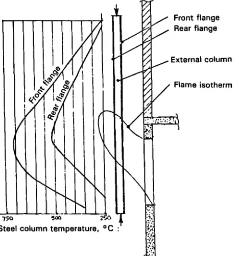
ii) CTICM structural response tests
Recent work' 3 ' in France for the Commission of the European Communities
(ECSC-EEC-EAEC) examined beam/column interaction where the beam was loaded
column was placed outside the fire compartment and was subjected to
non-uniform heating. The structural configuration is shown in Figure.
1.1 g . Typical steel temperature profiles are given in Figure 1.15 and it
is interesting to note the large temperature difference of nominally 200°C
between front and rear flanges which agrees with the Fire Research Station
findings.
In Kruppa's comprehensive report 1.32 of the work it appears that some
tests were conducted with pin-ended columns (analagous to the FRS model
tests described later), but in the majority of tests with a beam framing
in at mid-height to the column since this was considered to be more
representative of practice in multi-storey buildings.
The CTICM work showed that column failure could take place In several
different ways. One way, of particular relevance to the present work,
involved failure "by plastification of the hottest zone of the column
after the column had returned (from bowing towards the fire) to Its
initial position, and then has continued to deform away from the fire".
It was also found that, f or sections with flanges parallel to the facade
(ie parallel to the plane of heating), a lightly loaded column would
ultimately fail in its plane of high inertia, away from the fire.
Figures 1.16 and 1.17 reproduce figures in the reference. Figure 1.16
shows the deformation half-way up the columns away from the fire. It can
be seen that In two tests (Tests 5 and 6) the columns initially bowed
towards the fire, then straightened out and failed by bowing away from the
fire. The writer has called this unexpected behaviour "reverse direction
illustrates the consistent shape of the curves and the rapid failure
judged to have occurred when the column had attained its original length
after expansion and "contraction". Kruppa's work was not known to the
writer at the time of planning the model column tests reported later
herein.
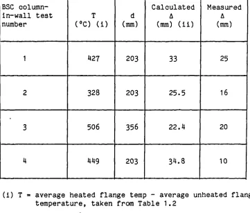
iii) BSC structural response tests
The British Steel Corporation Swinden Laboratories has, also recently,
undertaken I column-in-wall fire resistance tests133''3''35,
which are summarised in Table 1 .2. These were undertaken in the
expectation that the unexposed portion of the column would be at a lower
temperature and thus able to contribute to support the design load for a
longer period than If the column was exposed to fire on all faces. In
each test a pair of identical I-section members, spaced approximately 1 .3
metres apart, formed columns in part of a 3 metre x 3 -metre double leaf
cavity masonry wall specimen. Figure 1.18 shows a horizontal section
through a column used in Test 1, and the S-shaped temperature profiles at
30, 60 and 90 minutes.
The masonry did not carry any vertical load but was able to give lateral
restraint to the web of the I-section, so that the columns could not
buckle about the minor (yy) axis. However, In calculating the design load
It was assumed f or all tests, that failure would occur about the minor
(yy) axis. The height of each I-section column between welded end plates
was 3 m. The amount of rotational restraint at the ends in each test was
uncertain and for the purpose of calculating the design load according to
BS !1149 Part 2 : 1969, effective lengths between 0.75 L and 1.0 L were
Data used in the design load calculations are given in Table 1.2. The
test loads varied from 4O to 115 per cent of the maximum permissible
loads. Table 1.2 also includes heated and unheated flange temperatures
when maximum mid-span bowing occurred, first towards and then away from
the furnace. In all k tests the phenomenon of reverse direction bowing
occurred, as in the CTICM tests.
To see if the observed Initial mid-span bowing toward the furnace was
dominated by thermal bowing, the unrestrained thermal bow was calculated
using Equation (3.6) given in 3.2. The data, given in Table 1.3, show
that the calculated mid-height displacements are of the right order and
are generally greater than the measured displacements. There is however a
little uncertainty about the accuracy of the mid-height displacement
measurements made in the experiment - they were measured only at
mid-height relative to a fixed point in space and not relative to the
upper and lower ends of the colum which, in the writer's view, would have
been preferable since this would avoid the dubious assumption that the top
and bottom of the columns did not move perpendicular to the plane of the
specimen wall as the test progressed.
What, then, are the practical implications of the column-in-wall concept?
There is no doubt that survival times can be usefully extended. Assuming
a limiting temperature of 550°C, the 203 x 203 x 52 kg/rn section would
only achieve a fire resistance of approximately 15 minutes when fully
loaded and exposed to heat on all sides in the BS 476 : Part 8 : 1972 fire
resistance test' •36 . The results summarised in Table 1.2 show that a
fire resistance of' slightly more than 30 minutes is feasible when such a
possible to achieve a 3 hour fire resistance when the load is 140% of the
maximum allowable (see results for Test 3 in Table 1.2). It also appears
that the fire-exposed flange can be allowed to reach temperatures in
excess of 900°C when the column is fully loaded - compare this with
nominally 550°C when uniformly heated on all faces and similarly fully
loaded. Some other considerations are described in Chapter 8.
This small selection of fire test data shows that temperature differences
across partly protected steel I-section members can be appreciable, and in
excess of 700°C. Such members can achieve fire resistances in excess of 1
hour and this should be compared with a fire resistance of 15 minutes f or
a free standing unprotected 203 x 203 mm x 52 kg/rn column carrying its
maximum design load corresponding to a stress of 138 N/mm2.
1.9 Objectives and scope of research
It has been shown that the main thrust of international experimental a.oL
analytical work has been to elucidate factors affecting the structural
response of steel members heated uniformly across the section, and the
most recent authoritative work to emerge in Europe which demonstrates this
point is the ECCS Recommendations' •26 But these findings cannot be
applied to members whose sections have non-uniform temperature
distributions across them.
It has also been shown that there has been surprisingly little theoretical
work aimed at predicting the structural response of building elements such
as beams, columns, walls and floors when subjected to non-uniform heating.
In the case of external steelwork the research effort has tried to