1
Non-Linear Autopilot Design Using the Philosophy of
Variable Transient Response
John M. Counsell1, Joseph Brindley2 and Malcolm Macdonald3 University of Strathclyde, Glasgow, Scotland, UK
The novel non-linear controller design methodology of Variable Transient Response (VTR) is presented in this research. The performance of VTR is compared to that of successful non-linear controller designs (such as Robust Inverse Dynamics Estimation and a traditional autopilot design) by application to a non-linear missile model. The simulated results of this application demonstrate that the inclusion of VTR into the RIDE design results in a 50% improvement in response time and 100% improvement in settling time whilst achieving stable and accurate tracking of a command input. Analysis demonstrates that VTR dynamically alters the system’s damping, resulting in a non-linear response. The system stability is analysed during actuator saturation using non-linear stability criteria. The results of this analysis show that the inclusion of VTR into the RIDE design does not compromise non-linear system stability.
Nomenclature
d = missile diameter e = error signal
= missile angle of incidence
trim = trimmed missile angle of incidence LDU = upper actuator deflection limit LDL = lower actuator deflection limit LRU = upper actuator rate limit LRL = lower actuator rate limit m = missile mass
M = Mach number
Pd = dynamic pressure qm = measured pitchrate r = regulator
S = wetted surface area Ta = air temperature u = actuator deflection uc = control signal
ueq = equivalent control signal
= estimated equivalent control signal a = actuator damping ratio
g = gyroscope damping ratio s = damping ratio for RIDE system VTR = damping ratio for VTR system Vm = total forward velocity
v = missile forward velocity a = actuator natural frequency g = gyroscope natural frequency s = natural frequency for RIDE system
1
Professor (BRE Centre), Mechanical Engineering, AIAA Member 2
PhD Student, Mechanical Engineering, AIAA Member 3
2 VTR = natural frequency for VTR system
w = feedback signal
I.
Introduction
guided missile’s performance is largely determined by its speed of response and accuracy in tracking an autopilot’s demanded input. This is because any delay in response to the navigation command will result in an increased target missed distance. In order to achieve the fastest possible system response the missile’s actuators must be driven at maximum power for extended periods of time. Conventional linear controller designs, such as PI or PID, prevent the actuators from saturating for prolonged periods of time as stability would be compromised.1 Phelan addressed this issue with the Intelligent Pseudo Derivative Feedback (IPDF) controller by invoking a switching surface which ensured stability during periods of discontinuous nonlinear behaviour. Bradshaw and Counsell improved on the IPDF design with the Robust Inverse Dynamics Estimation (RIDE) control algorithm which resulted in greatly improved cross-coupling cancellation and disturbance rejection. 2,3,4 However, a frequent drawback of the RIDE controller is that it can be overdamped and slow to respond compared to traditional designs. This research demonstrates that by using the novel design method of Variable Transient Response (VTR) the RIDE algorithm can be enhanced to show a response improvement of 50% and a settling time improvement of 100 %. Furthermore, it is proven that the non-linear stability of the RIDE design is not compromised with the inclusion of VTR.
In the following sections, an overview of the traditional and RIDE controller designs is presented. The design methodology of VTR is explained in theory, and dynamic response is analysed. In order to analyse the system safety when the missile is pushed to its performance limits, criteria for stability during actuator saturation are derived for RIDE and VTR. Finally the performance of the traditional, RIDE and VTR designs are simulated with a non-linear missile model to asses both the transient response and stability when missile actuators are driven to power limits.
II.
Aerodynamic Missile Model
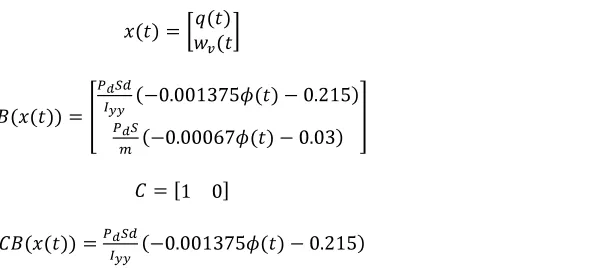
In order to evaluate performance each controller design was tested with a non-linear missile model. The aerodynamic model chosen was that of a hypothetical tail controlled air-to-air missile.2 The missile model assumes no roll rate, zero roll angle, no sideslip, no yaw rate and as such is SISO and purely longitudinal. The two missile states (x(t)) are pitchrate, q(t) and vertical velocity, wv(t). The input is elevator deflection, (t). The objective of the autopilot is the control of q(t) therefore the output and feedback from the missile model is q(t). The full equations of motion are given below.
(1)
3
Table 2. Actuator and Gyroscope Properties
III.
Actuator Modelling and Feedback
In order for the model of the system to resemble reality as closely as possible, it is vitally important to represent any non-linear behaviour that would be present in a working missile. To design a control system without considering these effects can be severely detrimental to the performance and stability of the system, so much so that
failures can occur such as the Tornado pilot induced oscillation incident.5
The missile system contains continuous non-linearity (present in the aerodynamic model) and, most importantly, a number of discontinuous non-linearities such as control surface deflection and rate limits. These features combine to make a system that, whilst being only single-input single-output, is highly complex in its non-linear behaviour. The rate and deflection limits of the actuator are very significant in determining the system performance. For the case of missiles, the actuator is always undersized, which means that the maximum performance of the system is limited by the power of the actuator. Since actuator rate and deflection limits are determined by the available power, correct and accurate modelling of these limits is required.
For a skid-to-turn missile the second order dynamics of the actuator can be represented by a spring-mass damper system.
(8)
The gyroscope dynamics can also be modelled as such a system.
(9)
IV.
Non-Linear Controller Benchmarks
A. Traditional Body Rate Auto Pilot
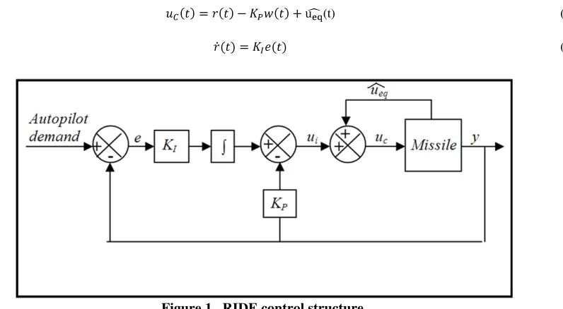
The traditional three loop autopilot design6,7 is comprised of an outer, acceleration loop and an inner, body rate segment, which itself is comprised of two further loops. Since a body rate (pitch rate) is the controlled output from the missile, the two loop traditional body rate controller is used as a simple benchmark. The design consists of a proportional feedback gain, KP, in the inner loop and an integral feedforward gain, KI, in the outer loop. The control algorithm is given by the following equations
(10) LRU = 1000 deg/s a = 200 rad/s
LRL = -1000 deg/s a = 0.7 LDU = 25 deg g = 500 rad/s LDL = -25 deg g = 0.7
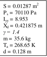
Table 1. Missile and Atmospheric Properties
S = 0.01287 m2 Ps = 70110 Pa Iyy = 8.953 Xd = 0.421875 m
= 1.4
[image:3.612.263.346.94.195.2] [image:3.612.225.391.510.575.2]4
(11)
The design is essentially the same as that of PDF therefore, to improve performance during actuator saturation, the IPDF switching law can be invoked. This consists of switching the error signal to zero when the actuator’s rate or deflection limits are reached. Therefore, the control law in these instances reduces to
(12)
B. Robust Inverse Dynamics Estimation
Robust Inverse Dynamics Estimation, or RIDE, is a highly effective controller design when used with severely non-linear systems and as such it is an excellent high performance benchmark.8 Importantly, its structure and design allows for easier analysis and implementation of VTR, which will be discussed in later sections. The missile’s equations of motion (Eqs. (1) to (7)) can be expressed in general non-linear state-space form
(13)
(14)
then the control to set , ueq(t), is given by
(15) By using this dynamic inverse, any disturbances, cross coupling, or non-linear plant dynamics can be negated. However, this can be difficult or sometimes impossible to realise as it requires full state feedback as well as accurate knowledge of both the aerodynamic and gravitational forces vector, f(x(t)), and the fin effectiveness matrix B(x(t)). Therefore, an estimate of ueq(t) has to be used which can then be implemented in a feedback control structure
(t) (16)
(17)
A reasonable estimate of ueq can be defined as.2,3
(18)
Since the structure of Eq. (16) will correct inaccuracies in , then robust and high performance control of non-linear systems can be achieved.
[image:4.612.129.527.384.603.2]5
When using the RIDE controller algorithm, any plant can be reasonably simplified to a first order system. This allows for classical analysis and design of RIDE which is applicable to all plant systems. Assuming that the estimate of ueq(t) is accurate (so that ) and that the actuators are fast such that , then from Figure 1 and Eq. (13), (14) and (15).
(19)
(20)
(21) If the system in question is single input single output (as is the case with this missile) and CB(x(t)) is slowly time varying compared to the closed loop response, then taking the Laplace transform of Eq. (21) at a trimmed value of CB(x(t))
(22)
Therefore, the plant is simplified to a first order system. The closed loop transfer function of the simplified plant and control system is
(23)
which is second order. Comparing this to a transfer function representing generalised second order dynamics1 (24)
it can be noted that the gains KI and KP can be calculated for a designed system natural frequency and damping ratio. (25)
(26)
(28)
(29)
V.
Variable Transient Response
Consider a commanded output, yc. Ideal controller performance could be described by the output, y(t), reaching yc in as little time as possible whilst remaining stable and damping any disturbances when the setpoint is reached. In order to achieve this high performance response, the controller must be very responsive during the rise period, but simultaneously must be very stable when tracking yc. In essence, when y(t) – yc is large, the system response is more important than stability. When y(t) – yc is small, the reverse is true. What is being described by these statements is a transient change in system damping inversely proportional to the error (y(t) – yc) and a directly proportional change in system natural frequency.
Relationships between natural frequency and error, and damping and error can be proposed that meet these requirements (where X and Y are tuneable coefficients and K is a function of the plant).
6
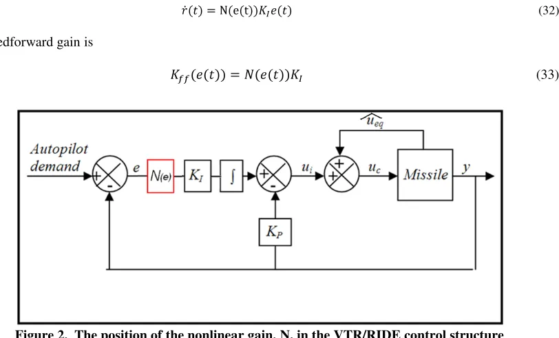
Considering the RIDE control system, this relationship can be achieved if a nonlinear gain is placed before the integrator in the forward path of the outer loop, as shown in Figure 2. The regulator is now
(32)
and the total feedforward gain is
(33)
Assuming the plant order reduction described in the previous section Eq. (23) then the natural frequency and damping ratio of the system is
(34)
(35)
Since N(e(t)) is a nonlinear function being used in a linear transfer function analysis, it is necessary to use describing function analysis5 in order to design Ne((t)) so that the relationships in Eq. (30) and (31) are satisfied. Therefore, if
(36)
then the describing function is
(37)
If the describing function of N(e(t)) is substituted into Eqs. (34) and (35) then the following relationships are obtained
(38)
(39)
which demonstrates that by using the nonlinear gain, N(t), in conjunction with the RIDE controller, dynamic control of system damping and natural frequency can be achieved which conforms to the desired relationships stated in Eqs. (30) and (31). This design is referred to as Variable Transient Response (VTR).
[image:6.612.134.540.105.351.2]7
Whilst equations Eqs. (38) and (39) show the system response characteristics for a specific error value, they do not tell us about the overall system transient response. In order to establish relations that provide this information, the average of Eqs. (38) and (39) for a maximum and minimum error must be determined. The average values of natural frequency and damping ratio are given by the following expressions
(40)
(41)
Assuming that the system starts at a trimmed state at which the output is zero, the initial error (ei) will be equal to the setpoint (sp). Also assuming that there will be no or little overshoot, the final error (ef) will be zero. Therefore, expressions for average damping ratio and natural frequency can be formed which describe the overall system transient response.
(42)
(43)
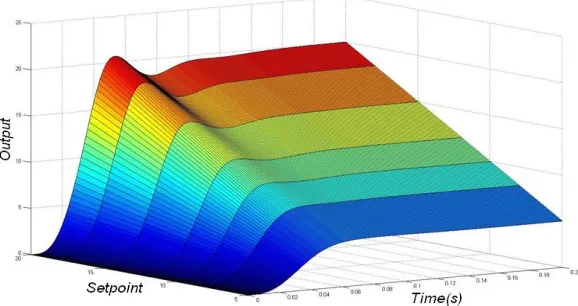
Eqs. (42) and (43) can then be solved simultaneously to obtain VTR parameters X and Y for a desired system response. These relationships also reveal that damping and natural frequency are dependent on setpoint. If the VTR controller is tuned for a given setpoint then, keeping the same controller parameters, if the setpoint is raised the response will be underdamped and, if lowered, the response will be overdamped (see Figure 3). This can be corrected either by finding a compromise by tuning X and Y so that the system is not over-damped for small setpoints or under-damped for large setpoints, or by simply scheduling X and Y with setpoint.
VI.
Safety During Actuator Saturation for RIDE and VTR
When the control signal, uc(t), has reached the upper or lower actuator limits, uc(t) must either remain constant or decrease in order to maintain safe control. This can be expressed as
(44) Figure 3. The relationship between setpoint and overall system damping for
[image:7.612.155.444.417.570.2]8 when
or (45)
If the error signal is set to zero when the actuator deflection limit is reached, an expression for the rate of change of control signal with time for RIDE can be derived.
(46) From Eq. (18)
(47) (48) With reference to Eq. (25)
(49) Therefore, assuming that
(50) By dividing by uc(t) and g two criteria are formed:
When and
(51)
When and
(52)
By combining these two expressions, a single criterion can be formed, which, when actuator limits are reached, sets limits that must remain between in order to ensure stability.
(53) This criterion demonstrates that, when actuator limits are reached, safety can be ensured simply by setting the error signal to zero, providing that steady state is reachable (i.e. the ueq(t) control is attainable within actuator limitations). If VTR is used and the error is reset as with RIDE then this criterion remains unaffected. This demonstrates that non-linear stability is not compromised by the addition of VTR to the RIDE algorithm.
VII.
Controller Design
A. Traditional Body Rate Autopilot Design
9
(54)
Controller gains were then designed using this relation as a guide.
B. RIDE Design
The RIDE controller design requires that the matrix CB be identified and the scalar gains g and p be designed. It is clear from Eqs. (1) and (2) that
(55)
(56)
(57) (58)
The values of g and p are based on s and s. These values were designed so that there was sufficient margin between the actuator and system bandwidths and that there was to be no or little overshoot. The assigned values of g, p, s and s are shown in Table 4.
Eq. (58) shows that CB(x(t)) is nonlinear and time variant. It can be noted from Eq. (18) that it is possible to use the non-linear CB(x(t)) matrix for ueq calculation. However, it can be noted for Eqs. (25) and (26), that the gains KI and KP must be calculated using the linear time invariant CBtrim.
C. VTR Design
When VTR is introduced to the RIDE controller design, the scalar gains g and p are not required to be adjusted. Simply the values of the VTR coefficients X and Y have to be designed for desired performance. The initial values of X and Y were calculated using Eqs. (42) and (43) for a range of setpoints (from 1 rad/s to 10 rad/s) with an assigned natural frequency and damping ratio of 75 rad/s and 0.9 respectively. These values were then tuned manually until desired performance for each setpoint was achieved. The values of X and Y were then scheduled with setpoint to ensure consistent performance.
Table 3. Traditional body rate autopilot gains
[image:9.612.215.517.281.416.2]10
It can be noted from Eqs. (33) and (36) that there is no limit on the maximum value of the total feedforward gain (Kff(t)). Therefore, to avoid instability caused by a very large error, the maximum value of Kff (t) is limited.
VIII.
Simulation Results
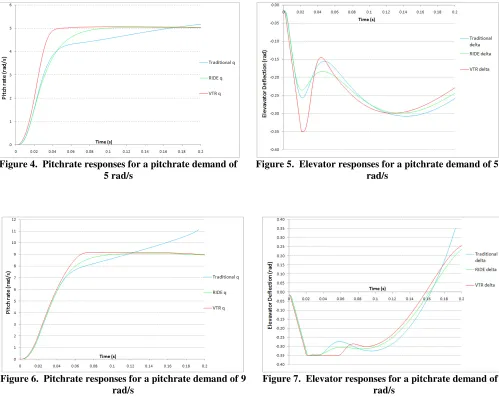
The three controller designs were simulated for 0.2 seconds with the non-linear missile model at a Mach number of 2.5 and a trimmed value of incidence of 10 deg. It is useful to describe some design specifications in order to compare performance between the controller designs. It was required that a step input pitchrate of 5 rad/s and 9 rad/s would be tracked by the controllers. Simulating a small and then large input allows for investigation of autopilot performance when actuators are unsaturated and saturated. In both cases the desired response was to be as fast as possible with little or no overshoot, and stable and accurate tracking of the setpoint.
Figure 4. Pitchrate responses for a pitchrate demand of 5 rad/s
Figure 5. Elevator responses for a pitchrate demand of 5 rad/s
Figure 6. Pitchrate responses for a pitchrate demand of 9 rad/s
[image:10.612.59.558.209.625.2] [image:10.612.60.567.421.602.2]11
Examining the 5 rad/s demand results it can be seen that the traditional autopilot does not fulfil the performance criteria set out previously. Response time is acceptable, however, the setpoint is not accurately tracked. The RIDE autopilot improves upon the performance of the traditional design by exhibiting similar response time, but with addition of excellent setpoint tracking. Furthermore the actuator movement induced by the RIDE design is, in this case, reduced compared to that of the traditional design. It is important to mention that the response of the RIDE design cannot be improved without overshoot and instability occurring. The performance of the VTR autopilot is clearly superior to both the RIDE and traditional designs. Not only is the response time significantly improved (and settling time improved further still) but this is achieved without compromising stability and accuracy of setpoint tracking. In order to achieve this performance improvement, the VTR autopilot pushes the actuator much harder, with the deflection limit of 0.35 rad briefly reached.
When a pitchrate of 9 rad/s is requested, all three designs immediately saturate the actuator in rate. This means that the response of all three designs is the same. However, when the setpoint is approached, differences in performance become apparent. The traditional design does not track the setpoint and becomes unstable resulting in the simulation diverging after 0.19 seconds. The actuator reaches and then remains on its deflection limit for 0.02 seconds. Whilst it is not possible to check using a stability criteria if this is the cause of the instability, it is most likely a contributing factor along with the “soft” aerodynamic nonlinearities.
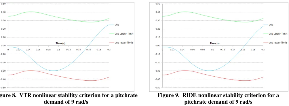
The RIDE autopilot fares much better under these operating conditions. The pitchrate response is very similar to that seen when a smaller pitchrate was requested. This demonstrates some of the robust characteristics of the RIDE design. The actuator briefly hits the deflection limit but the autopilot remains perfectly stable as demonstrated by the non-invalidation of the nonlinear stability criterion.
The VTR design displays similar performance to that of RIDE. Response time is the same but the setpoint is reached and tracked much sooner. Importantly, the results demonstrate that the VTR autopilot is able to remain stable during prolonged actuator saturation. The non-linear stability of VTR design is confirmed by ueq safely remaining between the upper and lower stability limits.
IX.
Further Work
Future work will focus on extending the VTR design from SISO to MIMO and simulation analysis using a multivariable missile model. Further research will also entail an investigation into what is the optimum relationship between error and natural frequency for the VTR design by modifying Eqs. (30) and (31).
X.
Conclusion
This work demonstrates that the Variable Transient Response controller design (VTR) has the ability to significantly improve transient response time of a body rate autopilot system designed using either traditional or RIDE methods. Importantly, the VTR design achieves this improved response time without any penalty in overshoot or oscillations in the transient response. The improved response will result in a much reduced miss distance, which will in turn reduce the size of warhead required. The outcome of this is the increased feasibility of a smaller, lighter and more agile missile.
Figure 8. VTR nonlinear stability criterion for a pitchrate demand of 9 rad/s
[image:11.612.60.562.73.257.2]12
The novel VTR design method has been described. The first step in this design method of the closed-loop response can still be designed using the effective RIDE method. In the second step the VTR nonlinearity can be added to optimise the response time. It has been further demonstrated that the high performance and stability of RIDE during severe nonlinear behaviour (such as actuator saturation) is still preserved when VTR is added. The understanding of this stability has been enhanced by the development of a new criterion, which offers insight into what the limitations are for the RIDE controller to remain stable when actuator limits are reached. It has been shown that this criterion remains unchanged when the VTR nonlinearity is added to the RIDE design.
Finally, VTR can be very easily explained to a team of system engineers and be easily implemented in an embedded system for a missile autopilot.
References
1
Franklin, G., Powell, J. D., Emami-Naeini, A., Feedback Control of Dynamic Systems, 5th ed., Prentice Hall, 2005. 2Counsell, J. M., “Optimum and Safe Control Algorithm (OSCA) for Modern Missile Autopilot Design,” Ph.D. Thesis,
Mechanical Engineering Department, University of Lancaster, 1992.
3Muir, E., Bradshaw, A., “Control Law Design for a Thrust Vectoring Fighter Aircraft using Robust Inverse Dynamics
Estimation,” Proceedings of the IMechE, Vol. 210, May 1996, pp. 333, 343. 4
Counsell, J. M., Bradshaw, A., “Design of Autopilots for High Performance Missiles,” Proceedings of the IMechE, Vol. 206, February 1992, pp. 75, 84.
5Fielding, C., Flux, P. K., “Non
-linearities in Flight Control Systems,” Royal Aeronautical Society Journal, Vol. 107, No. 1077, 2003, pp. 673, 686.
6Mracek, C. P., Ridgely, D. B., “Missile Longitudinal Autopilots: Comparison of Multiple Three Loop Topologies,” AIAA Guidance, Navigation, and Control Conference, CP849, Vol. 1, AIAA, Washington, DC, 2005.
7
Urban, T. J., Iwaskiw, P., Iglesias, P. A., “Understanding Missile Autopilot design Using the H∞ Loop Shaping Design
Procedure,” IEEE International Conference on Control Applications, Vol. 1, pp. 236, 242, IEEE, 1999. 8