electronic reprint
ISSN: 2056-9890
journals.iucr.org/e
Crystal structure of 3-chloro-
N
-(2-nitrophenyl)benzamide
Rodolfo Moreno-Fuquen, Alexis Azc´arate and Alan R. Kennedy
Acta Cryst.
(2015). E
71
, o674
IUCr Journals
CRYSTALLOGRAPHY JOURNALS ONLINE
This open-access article is distributed under the terms of the Creative Commons Attribution Licence
http://creativecommons.org/licenses/by/2.0/uk/legalcode, which permits unrestricted use, distribution, and reproduction in any medium, provided the original authors and source are cited.
Crystal structure of 3-chloro-
N
-(2-nitro-phenyl)benzamide
Rodolfo Moreno-Fuquen,a* Alexis Azca´rateaand Alan R. Kennedyb
a
Departamento de Quı´mica, Facultad de Ciencias Naturales y Exactas, Universidad del Valle, Apartado 25360, Santiago de Cali, Colombia, andb
WestCHEM, Department of Pure and Applied Chemistry, University of Strathclyde, 295 Cathedral Street, Glasgow G1 1XL, Scotland. *Correspondence e-mail: rodimo26@yahoo.es
Received 2 August 2015; accepted 3 August 2015
Edited by W. T. A. Harrison, University of Aberdeen, Scotland
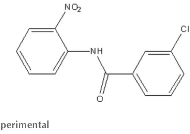
In the title compound, C13H9ClN2O3, the mean plane of the
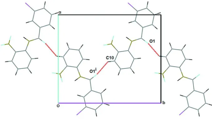
central amide fragment (r.m.s. deviation = 0.016 A˚ ) subtends dihedral angles of 15.2 (2) and 8.2 (2) with the chloro- and nitro-substituted benzene rings, respectively. An intra-molecular N—H O hydrogen bond generates anS(6) ring. In the crystal, molecules are linked by weak C—H O hydrogen bonds, formingC(7) chains which propagate along [010], but no Cl Cl short contacts are observed.
Keywords:crystal structure; benzamide; hydrogen bonding; halogen– halogen interactions.
CCDC reference:1416793
1. Related literature
For halogen–halogen interactions in benzanilide compounds, see: Veneret al.(2013); Nayaket al.(2011).
2. Experimental
2.1. Crystal data
Monoclinic,P21=c
a= 12.6300 (9) A˚
b= 14.1462 (12) A˚
c= 6.7797 (6) A˚ = 105.475 (7)
V= 1167.39 (17) A˚3
Z= 4
MoKradiation = 0.33 mm1
T= 123 K
0.400.080.05 mm
2.2. Data collection
Oxford Diffraction Gemini S diffractometer
Absorption correction: multi-scan (CrysAlis PRO; Oxford
Diffraction, 2010)
Tmin= 0.839,Tmax= 1.000
10366 measured reflections 10366 independent reflections 7015 reflections withI> 2(I)
2.3. Refinement
R[F2> 2(F2)] = 0.068
wR(F2) = 0.179
S= 1.00 10367 reflections 177 parameters
H atoms treated by a mixture of independent and constrained refinement
max= 0.78 e A˚3
[image:2.610.68.260.576.711.2]min=0.49 e A˚3
Table 1
Hydrogen-bond geometry (A˚ ,).
D—H A D—H H A D A D—H A
N1—H1N O2 0.98 (7) 1.75 (7) 2.612 (6) 144 (6) C10—H10 O1i
0.95 2.39 3.158 (7) 138
Symmetry code: (i)xþ1;y1 2;zþ
3 2.
Data collection: CrysAlis PRO (Oxford Diffraction, 2010); cell
refinement: CrysAlis PRO; data reduction: CrysAlis PRO;
program(s) used to solve structure: SIR92 (Altomareet al., 1994); program(s) used to refine structure:SHELXL2014(Sheldrick, 2015); molecular graphics: ORTEP-3 for Windows (Farrugia, 2012) and Mercury(Macraeet al., 2006); software used to prepare material for publication:WinGX(Farrugia, 2012).
Acknowledgements
RMF is grateful to the Universidad del Valle, Colombia, for partial financial support.
Supporting information for this paper is available from the IUCr electronic archives (Reference: HB7476).
References
Altomare, A., Cascarano, G., Giacovazzo, C., Guagliardi, A., Burla, M. C., Polidori, G. & Camalli, M. (1994).J. Appl. Cryst.27, 435.
Farrugia, L. J. (2012).J. Appl. Cryst.45, 849–854.
Macrae, C. F., Edgington, P. R., McCabe, P., Pidcock, E., Shields, G. P., Taylor, R., Towler, M. & van de Streek, J. (2006).J. Appl. Cryst.39, 453–457. Nayak, S. K., Reddy, M. K., Guru Row, T. N. & Chopra, D. (2011).Cryst.
Growth Des.11, 1578–1596.
Oxford Diffraction (2010).CrysAlis PRO. Oxford Diffraction Ltd, Yarnton, England.
Sheldrick, G. M. (2015).Acta Cryst.C71, 3–8.
Vener, M. V., Shishkina, A. V., Rykounov, A. A. & Tsirelson, V. G. (2013).J. Phys. Chem. A,117, 8459–8467.
supporting information
sup-1
Acta Cryst. (2015). E71, o674
supporting information
Acta Cryst. (2015). E71, o674 [doi:10.1107/S2056989015014620]
Crystal structure of 3-chloro-
N
-(2-nitrophenyl)benzamide
Rodolfo Moreno-Fuquen, Alexis Azc
á
rate and Alan R. Kennedy
S1. Comment
The crystal structure determination of 3-chloro-N-(2-nitrophenyl)benzamide (I), is part of a study on benzanilides carried out in our research group, and it was obtained from the reaction between 3-chlorobenzoic acid and 2-nitroaniline
mediated by the presence of thionyl chloride. The study of intermolecular halogen-halogen interactions is a current problem and several authors have presented interesting results. Halogen-halogen short interactions, in other similar
studies, show Cl···Cl distances of the order of 3.8 Å. Theoretical studies of density analysis, varying the Cl···Cl distance from 3.0 to 4.0 Å, using DFT solid state program, have been undertaken (Vener et al., 2013). Geometric considerations in halogen-halogen interactions, for various benzanilide systems, showed different behaviors. Interactions of fluorine with other halogens Cl, Br, I, in different benzanilide systems, include interactions type: trans, cis or L-geometry (Nayak et al.,
2011). The molecular structure of (I) is shown in Fig. 1. The central amide moiety, C8—N1-C7(═O1)—C1, is essentially planar (r.m.s. deviation for all non-H atoms = 0.0164 Å) and it forms dihedral angles of 15.2 (2)° with the C1-C6 and 8.2 (2)° with the C8-C13 rings respectively. In the crystal structure (Fig. 2), molecules are linked by weak C-H···O
intermolecular contacts. The C10-H10···O1 hydrogen bond interactions are responsible for crystal growth parallel to (2 0 -2). In this interaction, the C-H in the molecule at (x,y,z) acts as a hydrogen-bond donor to O1 atom of the carbonyl group at (-x+1,+y-1/2,-z+3/2). These interactions generate C(7) chains of molecules along [010]. Other intra H···O and N-H···N are observed (see Table 1, Nardelli, 1995). The shorest Cl···Cl contact distance in this structure is 3.943 (3) Å.
S2. Experimental
The title molecule was synthesized taking 0.200 g (1.270 mmol) of 3-chlorobenzoic acid and it was placed under reflux with 2 mL of thionyl chloride for two hours. After this time an equimolar amount of o-nitroaniline, dissolved in 10 mL of acetonitrile and allowed to reflux at constant stirring for 3 hours was added. The final solution was left to slow
evaporation to obtain yellow crystals. [m.p. 399 (1)K].
S3. Refinement
All Hm atoms were positioned in geometrically idealized positions, C—H = 0.95 Å, and were refined using a
riding-model approximation with Uiso(H) constrained to 1.2 times Ueq of the respective parent atom. H1N atom was found from
Figure 1
The molecular structure of (I) with displacement ellipsoids drawn at the 50% probability level. H atoms are shown as spheres of arbitrary radius.
Figure 2
Part of the crystal structure of (I), showing the formation of C(7) chains along [010] [Symmetry code: (i) -x + 1, y 1/2,
-z + 3/2].
3-Chloro-N-(2-nitrophenyl)benzamide
Crystal data
C13H9ClN2O3
Mr = 276.67 Monoclinic, P21/c
a = 12.6300 (9) Å
b = 14.1462 (12) Å
c = 6.7797 (6) Å
β = 105.475 (7)°
V = 1167.39 (17) Å3
Z = 4
F(000) = 568
Dx = 1.574 Mg m−3
Melting point: 399(1) K Mo Kα radiation, λ = 0.71073 Å Cell parameters from 10366 reflections
θ = 3.3–27.0°
µ = 0.33 mm−1
[image:4.610.136.475.312.504.2]supporting information
sup-3
Acta Cryst. (2015). E71, o674 Data collection
Oxford Diffraction Gemini S diffractometer
Radiation source: fine-focus sealed tube Graphite monochromator
ω scans
Absorption correction: multi-scan
(CrysAlis PRO; Oxford Diffraction, 2010)
Tmin = 0.839, Tmax = 1.000
10366 measured reflections 10366 independent reflections 7015 reflections with I > 2σ(I)
Rint = 0.000
θmax = 29.0°, θmin = 3.3°
h = −17→17
k = −17→17
l = −9→8
Refinement
Refinement on F2
Least-squares matrix: full
R[F2 > 2σ(F2)] = 0.068
wR(F2) = 0.179
S = 1.00
10367 reflections 177 parameters 0 restraints
Primary atom site location: structure-invariant direct methods
Secondary atom site location: difference Fourier map
Hydrogen site location: inferred from neighbouring sites
H atoms treated by a mixture of independent and constrained refinement
w = 1/[σ2(F
o2) + (0.0657P)2]
where P = (Fo2 + 2Fc2)/3
(Δ/σ)max < 0.001
Δρmax = 0.78 e Å−3
Δρmin = −0.49 e Å−3
Special details
Experimental. IR spectra was recorded on a FT—IR SHIMADZU IR-Affinity-1 spectrophotometer. IR (KBr), cm-1,
3348 (amide N–H); 1684 (amide, C=O); 1499 and 1342 (-NO2)
Absorption correction: CrysAlisPro, Agilent Technologies, Version 1.171.34.46 (release 25-11-2010 CrysAlis171 .NET) (compiled Nov 25 2010,17:55:46) Empirical absorption correction using spherical harmonics, implemented in SCALE3 ABSPACK scaling algorithm.
Geometry. All esds (except the esd in the dihedral angle between two l.s. planes) are estimated using the full covariance matrix. The cell esds are taken into account individually in the estimation of esds in distances, angles and torsion angles; correlations between esds in cell parameters are only used when they are defined by crystal symmetry. An approximate (isotropic) treatment of cell esds is used for estimating esds involving l.s. planes.
Refinement. Refinement of F2 against ALL reflections. The weighted R-factor wR and goodness of fit S are based on F2,
conventional R-factors R are based on F, with F set to zero for negative F2. The threshold expression of F2 > σ(F2) is used
only for calculating R-factors(gt) etc. and is not relevant to the choice of reflections for refinement. R-factors based on F2
are statistically about twice as large as those based on F, and R- factors based on ALL data will be even larger.
Fractional atomic coordinates and isotropic or equivalent isotropic displacement parameters (Å2)
x y z Uiso*/Ueq
H6 0.1616 0.4650 0.3786 0.041* C5 −0.0006 (5) 0.4342 (4) 0.2534 (10) 0.0384 (15) H5 −0.0242 0.4977 0.2241 0.046* C4 −0.0754 (5) 0.3611 (4) 0.2040 (10) 0.0337 (14) H4 −0.1505 0.3739 0.1401 0.040* C7 0.2650 (5) 0.3091 (4) 0.4934 (8) 0.0264 (13) C8 0.4049 (5) 0.1813 (4) 0.6035 (8) 0.0250 (13) C9 0.4207 (4) 0.0857 (4) 0.6545 (8) 0.0262 (13) C10 0.5238 (5) 0.0478 (4) 0.7497 (8) 0.0313 (14) H10 0.5320 −0.0174 0.7838 0.038* C11 0.6131 (5) 0.1073 (5) 0.7928 (9) 0.0346 (15) H11 0.6841 0.0831 0.8575 0.042* C12 0.6003 (5) 0.2006 (4) 0.7434 (8) 0.0339 (15) H12 0.6630 0.2406 0.7739 0.041* C13 0.4981 (4) 0.2388 (4) 0.6497 (8) 0.0298 (14) H13 0.4916 0.3041 0.6167 0.036* H1N 0.253 (6) 0.161 (5) 0.460 (10) 0.07 (3)*
Atomic displacement parameters (Å2)
U11 U22 U33 U12 U13 U23
Cl1 0.0180 (6) 0.0357 (8) 0.0445 (8) −0.0025 (6) −0.0009 (8) −0.0003 (8) O1 0.023 (2) 0.030 (3) 0.064 (3) −0.001 (2) −0.001 (2) −0.002 (2) O2 0.021 (2) 0.035 (3) 0.061 (3) −0.0019 (19) −0.004 (2) 0.001 (2) O3 0.034 (3) 0.028 (3) 0.072 (3) −0.002 (2) 0.003 (2) 0.012 (2) N1 0.017 (2) 0.028 (3) 0.032 (3) −0.002 (2) −0.002 (2) 0.000 (2) N2 0.017 (3) 0.032 (3) 0.041 (3) −0.002 (2) 0.006 (2) −0.001 (2) C3 0.018 (3) 0.028 (3) 0.028 (3) −0.001 (2) 0.005 (3) −0.002 (3) C2 0.018 (3) 0.030 (3) 0.031 (3) 0.001 (3) 0.004 (2) 0.003 (2) C1 0.019 (3) 0.031 (4) 0.028 (3) 0.000 (3) 0.005 (2) 0.003 (2) C6 0.023 (3) 0.028 (4) 0.048 (4) −0.001 (3) 0.002 (3) −0.001 (3) C5 0.024 (3) 0.033 (4) 0.053 (4) 0.007 (2) 0.000 (4) 0.009 (4) C4 0.022 (3) 0.039 (4) 0.039 (3) 0.007 (3) 0.005 (3) 0.005 (3) C7 0.022 (3) 0.027 (3) 0.027 (3) −0.002 (3) 0.001 (2) 0.003 (3) C8 0.016 (3) 0.031 (4) 0.025 (3) 0.001 (3) 0.001 (2) 0.000 (3) C9 0.015 (3) 0.029 (3) 0.032 (3) −0.004 (2) 0.003 (2) −0.001 (3) C10 0.023 (3) 0.029 (4) 0.040 (4) 0.001 (3) 0.005 (3) 0.003 (3) C11 0.018 (3) 0.043 (4) 0.041 (4) −0.002 (3) 0.003 (3) −0.002 (3) C12 0.017 (3) 0.042 (4) 0.040 (4) −0.004 (3) 0.005 (3) −0.004 (3) C13 0.022 (3) 0.028 (3) 0.038 (3) 0.002 (3) 0.005 (3) 0.002 (3)
Geometric parameters (Å, º)
supporting information
sup-5
Acta Cryst. (2015). E71, o674
N1—C8 1.405 (7) C8—C13 1.397 (7) N1—H1N 0.98 (7) C9—C10 1.397 (8) N2—C9 1.474 (7) C10—C11 1.374 (8) C3—C4 1.365 (7) C10—H10 0.9500 C3—C2 1.388 (7) C11—C12 1.360 (8) C2—C1 1.392 (7) C11—H11 0.9500 C2—H2 0.9500 C12—C13 1.387 (7) C1—C6 1.382 (7) C12—H12 0.9500 C1—C7 1.513 (8) C13—H13 0.9500 C6—C5 1.396 (7)
C7—N1—C8 127.8 (5) C5—C4—H4 120.2 C7—N1—H1N 126 (4) O1—C7—N1 124.1 (5) C8—N1—H1N 106 (4) O1—C7—C1 121.3 (5) O3—N2—O2 121.9 (5) N1—C7—C1 114.6 (5) O3—N2—C9 119.0 (5) C9—C8—C13 116.8 (5) O2—N2—C9 119.1 (5) C9—C8—N1 120.8 (5) C4—C3—C2 121.8 (5) C13—C8—N1 122.4 (5) C4—C3—Cl1 119.3 (4) C8—C9—C10 122.7 (5) C2—C3—Cl1 118.9 (4) C8—C9—N2 122.5 (5) C3—C2—C1 118.7 (5) C10—C9—N2 114.8 (5) C3—C2—H2 120.6 C11—C10—C9 118.3 (6) C1—C2—H2 120.6 C11—C10—H10 120.9 C6—C1—C2 120.0 (5) C9—C10—H10 120.9 C6—C1—C7 116.0 (5) C12—C11—C10 120.3 (6) C2—C1—C7 124.0 (5) C12—C11—H11 119.8 C1—C6—C5 120.0 (6) C10—C11—H11 119.8 C1—C6—H6 120.0 C11—C12—C13 121.7 (6) C5—C6—H6 120.0 C11—C12—H12 119.2 C4—C5—C6 119.9 (6) C13—C12—H12 119.2 C4—C5—H5 120.0 C12—C13—C8 120.1 (5) C6—C5—H5 120.0 C12—C13—H13 119.9 C3—C4—C5 119.5 (5) C8—C13—H13 119.9 C3—C4—H4 120.2
C8—N1—C7—C1 −176.5 (5) C9—C10—C11—C12 0.0 (9) C6—C1—C7—O1 9.1 (8) C10—C11—C12—C13 0.2 (9) C2—C1—C7—O1 −171.5 (6) C11—C12—C13—C8 0.1 (9) C6—C1—C7—N1 −170.6 (5) C9—C8—C13—C12 −0.6 (8) C2—C1—C7—N1 8.7 (8) N1—C8—C13—C12 −179.9 (5) C7—N1—C8—C9 162.7 (6)
Hydrogen-bond geometry (Å, º)
D—H···A D—H H···A D···A D—H···A
N1—H1N···O2 0.98 (7) 1.75 (7) 2.612 (6) 144 (6) C10—H10···O1i 0.95 2.39 3.158 (7) 138