The place of useful learning
The University of Strathclyde is a charitable body, registered in Scotland, number SC015263
Beckhoff and TwinCAT 3 System Development Guide
December 2015
1
Contents
1 Introduction ... 2
2 TwinCAT 3 Installation on Development PC ... 3
3 Connecting to a Hardware Controller... 4
4 TwinCAT 3 – Typical C++ Project Configuration ... 5
4.1 C++ Module ... 5
4.2 Assigning Module Instances to Processor Cores ... 9
4.3 Using a TMC File ... 11
4.4 Real-Time Monitoring ... 13
5 Integrating Simulink Models ... 16
5.1 Manual Compilation of Generated C++ Code within TwinCAT ... 16
5.2 Using Simulink-TwinCAT 3 Integration ... 18
6 References ... 20
Abbreviations
CPU Central Processing Unit IO Input or Output
2
1
Introduction
This document is a guide for setting up a Beckhoff hardware controller and a development PC. It is assumed that the development PC runs Windows 7 or Window 8/8.1, although other versions of Windows (including 32-bit and 64-bit) should also work. In particular, guidance is given on using C++ modules and integrating MATLAB Simulink models within TwinCAT 3.
This guide supplements existing Beckhoff documentation:
Webinar on TwinCAT 3 C++ integration:
http://multimedia.beckhoff.com/webinar/en/Webinar_TwinCAT_3_C_plusplus_Integra tion/default.htm
C++ Quick Start Guide:
https://infosys.beckhoff.com/english.php?content=../content/1033/tc3_c/7205759414 8625035.html&id=
The comprehensive manual is available here:
ftp://ftp.beckhoff.com/Document/automation/twincat3/TC1300_C_EN.pdf
The Beckhoff Information System (available at:
3
2
TwinCAT 3 Installation on Development PC
1. Install Visual Studio. There are several versions which are compatible with TwinCAT 3, and provide full functionality:
a. Free download: Visual Studio Community 2013 (available here: https://www.visualstudio.com/en-us/news/vs2013-community-vs.aspx). Note that TwinCAT 3 does not yet support the 2015 version.
b. Commercial: Visual Studio 2010, 2012, or 2013 (Professional, Premium, or Ultimate).
c. Within Strathclyde, the 2013 Professional edition can obtained from the Microsoft DreamSpark agreement, for teaching and non-commercial research purposes.
Note that if you install TwinCAT 3 without Visual Studio already installed, it will install “Visual Studio 2010 Shell”. This version is not suitable for C++ development or debugging.
2. Install Microsoft Windows Driver Kit (WDK) 7 and set up a Windows environment variable, as described by the following instructions: http://infosys.beckhoff.com/english.php?content=../content/1033/tc3_c/54043195639 122187.html&id=
3. Download TwinCAT 3 from http://www.beckhoff.co.uk/english.asp?download/tc3-downloads.htm?id=1905053019883865
a. You need to create an account on the Beckhoff website to access downloads. b. The specific download is found in the “Software” > “TE1xxx | Engineering” section, and is called “TwinCAT 3.1 – eXtended Automation Engineering (XAE)”.
4. When using TwinCAT 3, you might be asked to create or renew licenses. This is normal. Licenses last for one week, but can be simply renewed, perpetually, when needed. Licenses only need to be purchased for commercial work.
5. For 64-bit targets, two additional steps must be done:
a. On the development PC, set up digital driver signing. The process is given here:
http://infosys.beckhoff.com/english.php?content=../content/1033/tc3_c/63050 394893879947.html&id=. Note that step 3 is only required for executing the system on the local development machine.
b. On the hardware target, execute the “bcdedit /set testsigning yes” command (step 3 from the link above) and reboot the device.
4
3
Connecting to a Hardware Controller
A TwinCAT “target” is the hardware device which will ultimately execute a control system. Typically, the target will be one of the Beckhoff hardware controllers (such as the CX1020, etc.), but the local development PC can also be used as the target for testing purposes.
To use a hardware controller:
1. Connect one of the Ethernet interfaces on the Beckhoff controller to the development PC. This can be a direct connection, or via a switch. Set the PC's network interface IP address to be on the same subnet as the control. For example, if the controller’s IP address is 192.168.2.10 with a subnet mask of 255.255.255.0, then the PC’s IP address could be set to 192.168.2.20. Note that Beckhoff controllers must not be added to a corporate Windows domain, because this conflicts with the functionality. 2. Create a new TwinCAT 3 project (or use an existing project) in Visual Studio.
5
4
TwinCAT 3 – Typical C++ Project Configuration
This section describes adding a C++ module to a TwinCAT 3 project.
4.1 C++ Module
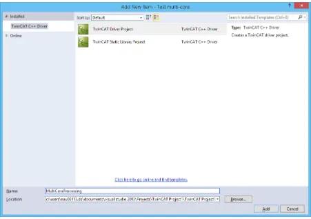
[image:6.595.72.523.200.517.2]In the Solution Explorer panel, right click on “C++” and “Add New Item...”. Select “TwinCAT Driver Project”, choose a name, and click on “Add”.
Figure 1: Initial C++ module creation
6
Figure 2: C++ module template
7
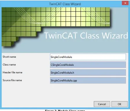
Figure 3: Module Class name
8
Figure 4: Example of initial generated code
However, this Module Class is merely “template”, and you must still create an instance (or “object”) of the Module Class to assign to a processor core on a target controller.
Right click on the C++ project, select “Add New Item”, and find your “published” module, as shown below:
[image:9.595.73.523.441.730.2]9
This means that you can create multiple object instances from the same Module Class template.
4.2 Assigning Module Instances to Processor Cores
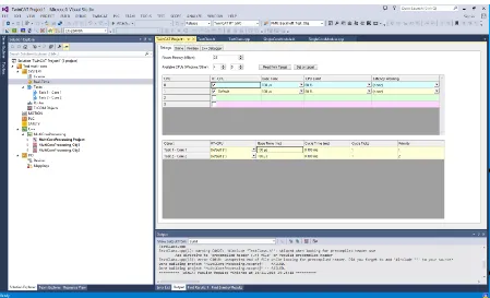
[image:10.595.73.522.175.448.2]In “SYSTEM” > “Real-Time”, enable the required CPU cores (you may first need to click “Read from Target”) and set the required Base Time:
Figure 6: Assigning module instances to processor cores
10
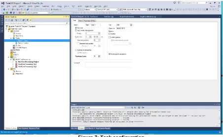
Figure 7: Task configuration
For each module instance, select the “Context” tab and assign the module to a task:
Figure 8: Task context mapping
More details on task configuration are available here:
[image:11.595.74.526.386.667.2]11
4.3 Using a TMC File
[image:12.595.74.523.140.414.2]The TMC file, with its associated editor GUI, defines the functionality of a C++ module. For example, Outputs – which are visible to other TwinCAT modules – can be defined:
Figure 9: Defining a module output using the TMC editor
In order to be able to monitor variables in real-time, select “Create symbol” in the editor:
[image:12.595.73.526.458.734.2]12
[image:13.595.74.528.119.398.2]After making changes to a TMC file, save the file, right click on the module, and select “TwinCAT TMC Code Generator”. This updates the generated code. The changes should automatically appear for all module instances:
Figure 11: Two Module Class objects, with a common definition
The definitions can be accessed from C++ code. For example, two output variables can be assigned values as follows:
[image:13.595.74.524.454.727.2]13
Once all required definitions have been added to the TMC file and the required C++ code has been added, the module can now be built, although this will also be done automatically when transferring to a target. Select “Activate Configuration” in the toolbar to run the project on the TwinCAT target.
Further TMC documentation is available here:
https://infosys.beckhoff.com/english.php?content=../content/1033/tc3_c/2702159848565172 3.html&id=.
4.4 Real-Time Monitoring
[image:14.595.73.525.251.569.2]Data in TwinCAT projects can be monitored with high granularity in real-time. Go to “File” > “Add” > “New Project...” > “TwinCAT Measurement”, then select the appropriate scope type:
Figure 13: Creating a new TwinCAT Measurement project
14
Figure 14: Adding data to plots
Add the relevant signals to your plot:
Figure 15: Selecting signals from the Target Browser
[image:15.595.74.520.392.669.2]15
Figure 16: Viewing plots of module data
16
5
Integrating Simulink Models
There are two approaches for integrating an algorithm or control system implemented in Simulink (which may include performance-critical components written directly in C) into the Beckhoff platform, and these approaches are described in the following subsections. Both approaches involve the automatic generation of a C or C++ code implementation of a Simulink model, using Simulink Coder [1], [2].
5.1 Manual Compilation of Generated C++ Code within TwinCAT
Simulink Coder can be used to create a C or C++ implementation of a Simulink model, which is intended to be optimised for embedded, real-time applications. For integration with TwinCAT 3, Simulink Coder should be configured to generate C++ code for a 32-bit x86 platform (unless a different controller unit architecture is being targeted). Double-precision floating-point numbers can be used.
The generated C++ code can be included in a TwinCAT 3 project within a C++ Module Class, using the template for “cyclic” tasks (see Figure 2). The code from Simulink Coder should wrap the Simulink model in a C++ class. An instance of this class should be defined as a protected member in the header file of the Module Class (i.e., not simply declared arbitrarily in the C++ code). The Simulink model should be initialised within the
SetObjStatePS() function within the main Module Class C++ file, for example:
// State transition from PREOP to SAFEOP //
// Initialize input parameters // Allocate memory
HRESULT CPMU_M_class::SetObjStatePS(PTComInitDataHdr pInitData) {
m_Trace.Log(tlVerbose, FENTERA); HRESULT hr = S_OK;
IMPLEMENT_ITCOMOBJECT_EVALUATE_INITDATA(pInitData);
// Simulink model initialization PMU_Beckhoff_Test_Obj.initialize();
m_Trace.Log(tlVerbose, FLEAVEA "hr=0x%08x", hr); return hr;
}
The task should be configured to execute on a particular time-base, such as 1 ms or 100 µs, which matches the time-step of the Simulink model. For example, the CX1020 controller unit – a relatively basic controller with a 1 GHz single-core CPU – can execute the phasor measurement (PMU) algorithm documented in [3] in real-time with a 100 µs time-base, requiring 30-40% of the CPU time1. This is illustrated in Figure 17.
1 This only includes the CPU time for the PMU algorithm; however, the additional CPU time
17
Figure 17: PMU algorithm CPU execution time
There are two caveats with this approach:
1. In TwinCAT 3, precompiled headers must be manually disabled for the imported Simulink source files. This is a simple change within the C++ compiler settings. 2. It is required to use platform-specific library calls for mathematical functions, which
are better suited for real-time operation, rather than those defined in the standard C “math.h” library. A simple method for achieving this is to replace the “#include <math.h>” line in the main C++ header file generated by Simulink Coder with:
#include <fpu87.h>
#include "math_h_defines.h"
where “math_h_defines.h” provides a mapping of the standard C versions to the
TwinCAT versions:
18
#define fmodabs fmodabs_ #define round round_
#define rounddigits rounddigits_ #define coubic coubic_
#define ldexp ldexp_ #define ldexpf ldexpf_ #define sinh sinh_ #define cosh cosh_ #define tanh tanh_ #define finite finite_ #define isnan isnan_ #define rands rands_
Note that this will result in compiler warnings, but allows the module to be built and executed.
5.2 Using Simulink-TwinCAT 3 Integration
[image:19.595.74.524.368.717.2]There is a Beckhoff software tool for directly integrating Simulink models with TwinCAT 3. This is achieved simply by selecting the TwinCAT 3 “target” with Simulink Coder (rather than the normal embedded target); once the code is generated, the module is automatically available within TwinCAT 3. A simple example, which illustrates the integration of a Simulink “block” model into the TwinCAT 3 user interface, is shown in Figure 18.
19
This tool is intended to be more convenient and to allow easier debugging than direct integration of C++ code as described in Section 5.1. Simulink model inputs and outputs are automatically identified in TwinCAT 3, as illustrated in the left of Figure 18. Signals in the Simulink model can be monitored in real-time whilst the project is executed on the target hardware. However, this approach requires a separate software licence and the code generation process typically takes significantly longer than for manual C++ code integration.
20
6
References
[1] MathWorks, “Simulink Coder - Generate C and C++ code from Simulink and Stateflow models,” 2012. [Online]. Available: http://www.mathworks.co.uk/products/simulink-coder/.
[2] A. J. Roscoe, S. M. Blair, and G. M. Burt, “Benchmarking and optimisation of Simulink code using Real-Time Workshop and Embedded Coder for inverter and microgrid control applications,” in Universities Power Engineering Conference (UPEC), 2009, pp. 1–5.
[3] A. J. Roscoe, “Exploring the Relative Performance of Frequency-Tracking and Fixed-Filter Phasor Measurement Unit Algorithms Under C37.118 Test Procedures, the Effects of Interharmonics, and Initial Attempts at Merging P-Class Response With M-Class Filtering,” IEEE Trans. Instrum. Meas., vol. 62, no. 8, pp. 2140–2153, Aug.