City, University of London Institutional Repository
Citation
:
Read, M. G., Stosic, N. and Smith, I. K. (2014). Optimization of Screw
Expanders for Power Recovery From Low-Grade Heat Sources. Energy Technology &
Policy, 1(1), pp. 131-142. doi: 10.1080/23317000.2014.969454
This is the published version of the paper.
This version of the publication may differ from the final published
version.
Permanent repository link:
http://openaccess.city.ac.uk/16606/
Link to published version
:
http://dx.doi.org/10.1080/23317000.2014.969454
Copyright and reuse:
City Research Online aims to make research
outputs of City, University of London available to a wider audience.
Copyright and Moral Rights remain with the author(s) and/or copyright
holders. URLs from City Research Online may be freely distributed and
linked to.
City Research Online:
http://openaccess.city.ac.uk/
publications@city.ac.uk
Full Terms & Conditions of access and use can be found at
http://www.tandfonline.com/action/journalInformation?journalCode=uetp20
Download by: [138.40.68.20] Date: 10 February 2017, At: 06:12
An Open Access Journal
ISSN: (Print) 2331-7000 (Online) Journal homepage: http://www.tandfonline.com/loi/uetp20
Optimization of Screw Expanders for Power
Recovery From Low-Grade Heat Sources
Matthew Read, Nikola Stosic & Ian K. Smith
To cite this article: Matthew Read, Nikola Stosic & Ian K. Smith (2014) Optimization of Screw Expanders for Power Recovery From Low-Grade Heat Sources, Energy Technology & Policy, 1:1, 131-142, DOI: 10.1080/23317000.2014.969454
To link to this article: http://dx.doi.org/10.1080/23317000.2014.969454
Published with license by Taylor & Francis Group, LLC© Matthew Read, Nikola Stosic, and Ian K. Smith
Published online: 12 Dec 2014.
Submit your article to this journal
Article views: 1415
View related articles
Energy Technology & Policy(2014)1, 131–142 Published with license by Taylor & Francis Group, LLC ISSN: 2331-7000 online
DOI: 10.1080/23317000.2014.969454
Optimization of Screw Expanders for Power Recovery From
Low-Grade Heat Sources
MATTHEW READ, NIKOLA STOSIC*, and IAN K. SMITH
Centre for Positive Displacement Compressor Technology, City University, London, United Kingdom
Received May 2014, Accepted July 2014
Abstract:
In systems for recovering power from low-grade heat sources, using twin screw machines to expand wet vapors, the power output depends on the conflicting requirements of high heat recovery and high working fluid temperatures, the dryness fraction of the fluid entering the expander, the rotor diameter and profile, the speed, and the built-in volume ratio. To obtain the best combination of these, for maximum power output per unit flow of a given heating medium, optimization methods and their associated numerical procedures can be used. This article focuses on the optimization of the geometry of a twin screw machine for the expansion of wet steam, with the aim of maximizing power output. Representative machine operating conditions are specified, and the methods used for the design of the machine are described. The predicted performance is compared with experimental data for the optimized machine, and close agreement is found between the predicted and measured results for power output, mass flow rate, and efficiency.Keywords:Screw expander, low-grade heat, optimization
Introduction
Hot gas or liquid streams at moderate to low temperatures, such as exhaust gases, geothermal brines, and engine cooling jacket water, are currently being extensively examined as heat sources for thermal power plants. A key problem to maximizing the effi-ciency and minimizing the cost of such systems is to obtain favorable temperature matching between the heat source and the working fluid in the primary heat exchanger through which both fluids pass. To this end, a variety of working fluids and cycles are used or have been proposed, all of which are based on the expansion of dry vapors.
The possibility of expanding fluid from either liquid or two-phase conditions adds an additional degree of freedom to both the working fluid and the cycle choice. By this means, higher working fluid temperatures can be obtained without the need for desuperheating the fluid leaving the expander. This results in higher efficiencies and reduced costs. Although this cannot be done with turbines, it is possible with screw expanders, which can
© Matthew Read, Nikola Stosic, and Ian K. Smith
This is an Open Access article. Non-commercial re-use, distribution, and reproduction in any medium, provided the original work is prop-erly attributed, cited, and is not altered, transformed, or built upon in any way, is permitted. The moral rights of the named author(s) have been asserted.
*Address correspondence to: Nikola Stosic, Centre for Positive Displacement Compressor Technology, City University, London EC1V 0BP, UK. Email:n.stosic@city.ac.uk
be designed with acceptable efficiencies and costs for systems developing power outputs of up to about 1 MW.
The best combination of the many variables involved, to obtain maximum power output at the lowest possible overall system cost, requires multivariable optimization. The performance of a power plant is very sensitive to the efficiency of its system com-ponents. For low-grade heat recovery systems with wet vapor expansion, the most important of these components is the screw machine. Optimization of its geometry for typical operating conditions is therefore essential.
Taniguchi et al.1described a detailed mathematical model of
two-phase expansion in screw machines, and this work has been taken as the main reference for further investigation of this pro-cess. Margolis2described his pioneering work in screw expander modeling, as well as Steidel, Pankow, and Brown, who described experimental investigation of a steam expander and its empirical modeling.3, 4 More work has been done in screw compressors
and published in textbooks—for example, by Amosov et al.5and Rinder.6
expander model in 1990, while Kauder and Zellermann11 and
Persson12have also presented work on the analysis and practical
application of screw expanders.
Smith13 published a fundamental consideration of the use of
screw machines for wet vapor expansion, and, more recently, Smith et al.14 give a thorough presentation of the theoretical considerations and mathematical models of the screw expander process. These have been used in this article for optimization of the screw expanders in low-grade heat recovery systems.
In order to make such computer models more readily acces-sible to designers and engineers, as well as to specialists, the authors have developed a suite of subroutines for the purpose of screw compressor design, as shown by Hanjalic and Stosic,15,16
as well as Stosic and Hanjalic.17,18 These can also be used for
screw expander optimization. Stosic et al.19 describe in detail
mathematical models of screw machines.
Screw Expander Features and Operation
In general, positive displacement machines have a wide range of application, particularly in the fields of refrigeration and com-pressed air production, and their total world production rate is in excess of 200 million units per annum. Paradoxically, but possi-bly because these machines are produced by comparatively small companies with limited resources, relatively little is spent on research and development programs on them, and there are very few academic institutions in the world that are actively promoting their improvement.
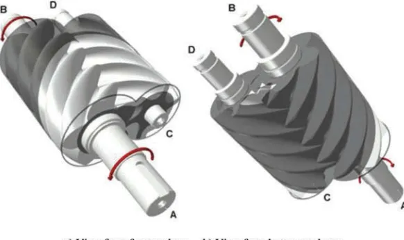
One of the most successful positive displacement machines currently in use is the screw compressor. This is shown in
Figure 1, and its principle of operation is based on volumetric changes in three dimensions rather than two. As shown, it con-sists of a pair of meshing helical lobed rotors, contained in a casing. The flutes formed between the lobes on each rotor form a series of working chambers in which gas or vapor is contained. Beginning at the top and in front of the rotors, shown in the dark shaded portion ofFigure 1, there is a starting point for each chamber where the trapped volume is initially zero. As rotation
proceeds in the direction of the arrows, the volume of that cham-ber increases as the line of contact between the rotor with convex lobes, known as the main rotor, and the adjacent lobe of the gate rotor advances along the axis of the rotors toward the rear. On completion of one revolution (i.e., 360◦) by the main rotor, the volume of the chamber is then a maximum and extends in helical form along virtually the entire length of the rotor. Further rotation then leads to reengagement of the main lobe with the succeeding gate lobe by a line of contact starting at the bottom and front of the rotors and advancing to the rear, as shown in the dark shaded portions inFigure 1b. Thus, the trapped volume starts to decrease. On completion of a further 360◦of rotation by the main rotor, the trapped volume returns to zero.
The dark shaded portions inFigure 1show the enclosed region where the rotors are surrounded by the casing, which fits closely round them, while the light shaded areas show the regions of the rotors, which are exposed to external pressure. Thus the large light shaded area inFigure 1acorresponds to the region exposed to the low-pressure port, while the small light shaded region between shaft ends B and D in Figure 1b corresponds to the region exposed to the high-pressure port.
As the front ends of the rotors pass across the low-pressure suction port, the space between the lobes is filled with the work-ing fluid. This fillwork-ing process continues until the trapped volume is at maximum. Further rotation then leads to cutoff of the chamber from the port and progressive reduction in the trapped volume. This leads to axial and bending forces on the rotors and also to contact forces between the rotor lobes. The com-pression process continues until the required pressure is reached when the rear ends of the passages are exposed to the discharge port through which the working fluid flows out at approximately constant pressure.
[image:4.612.157.448.550.723.2]It can be appreciated from examination of Figure 1 that, if the direction of rotation of the rotors is reversed, then the work-ing fluid will flow into the machine through the high-pressure port and out through the low-pressure port, and it will act as an expander. The machine will also work as an expander when rotating in the same direction as a compressor, provided that the suction and discharge ports are positioned on the opposite
Optimization of Screw Expanders
133
sides of the casing to those shown, since this is effectively the same as reversing the direction of rotation relative to the ports. An advantageous feature of such a configuration is that, unlike a reciprocating machine, it has a negligible clearance volume at the high-pressure end.
When operating as a compressor, mechanical power must be supplied to shaft A to rotate the machine. When acting as an expander, it will rotate automatically due to pressure difference, and power generated within it will be taken externally through shaft A.
The meshing action of the lobes, as they rotate, is the same as that of helical gears, but, in addition, their shape must be such that at any contact position, a sealing line is formed between the rotors and the casing in order to prevent internal leakage between successive trapped passages. A further requirement is that the passages between the lobes should be as large as possi-ble, in order to maximize the fluid displacement per revolution. Also, the contact forces between the rotors should be low in order to minimize internal friction losses between the expander mov-ing parts. A typical screw rotor profile is shown in Figure 2, where a configuration of 5 lobes on the main rotor and 6 lobes on the gate rotor is presented. The projected sealing line of the meshing rotors is shown in the axial plane on the left and in the cross section plane at the center, while the clearance distribution, between the two rotor racks in the transverse cross-section, scaled 50 times is shown above the rotors. The rotor racks represent the rotor profiles as formed on rotors of infinite radii, thus containing an infinite number of lobes.
[image:5.612.318.570.77.303.2]Screw machines have a number of advantages over other posi-tive displacement types. First, unlike reciprocating machines, the moving parts of screw machines all rotate and can therefore can run at much higher speeds due to absence of acceleration within their working cycle. Second, unlike vane machines, the contact forces within them are low, which makes them very reliable. Third, and far less well known, unlike the reciprocating, scroll, and vane machines, all the sealing lines of contact that define
[image:5.612.55.300.517.707.2]Fig. 2.Screw rotor profile: 1–main, 2–gate, 3–rotor external, 4–pitch circles, 5–sealing line, 6–clearance distribution, and 7–rotor flow area between the rotors and housing.
Fig. 3.An example of volumetric change with rotation in a screw expander.
the boundaries of each cell chamber decrease in length as the size of the working chamber decreases and the pressure within it rises. This minimizes the escape of gas from the chamber due to leakage during the compression or expansion process.
The adiabatic and volumetric efficiencies of screw machines are highly dependent on both the profile and number of the lobes in each rotor.
The volume and port area variation within one expander work-ing cycle is presentedFigure 3, and it is similar to that presented by Smith at al.20 The abscissa is set to zero at the point of cutoff of the inlet port, while the discharge port becomes exposed at the point of maximum volume. In practice, this point may be varied slightly with negligible effect on the performance.
Optimization Rationale
Among the optimization methods frequently used in engineer-ing are steepest descent, Newton’s method, Davidson-Fletcher-Powell’s method, random search, grid search method, search along coordinate axes, Powell’s method, and Hooke-Jeeves’s method. A widely used method for optimization of functions with several optima is the genetic algorithm, as discussed by Gen and Cheng.21 Genetic algorithms are flexible and robust
it has simple mathematical requirements, needing only the func-tion value and not its gradient. The disadvantage is that it is less suitable for discrete parameters—for example, if a choice between discrete component sizes is required. This method has been shown to achieve efficient and reliable optimization of twin-screw expanders, and it is described in more detail below.
The constrained simplex method emerged from the evolu-tionary operation method, which was introduced in the 1950s by Box22 and Box and Draper.23 The basic idea is to replace
the static operation of a process by a continuous and systematic scheme of slight perturbations of the control variables. The effect of these perturbations is evaluated, and the process is shifted in the direction of improvement. The basic simplex method was originally developed for evolutionary operation, but it was also suitable for the constrained simplex method. Its main advantage is that only a few starting trials are needed, and the simplex immediately moves away from unsuitable trial conditions. The simplex method is especially appropriate when more than three control variables are to be perturbed, and the process requires a fresh optimization with each new set of input data.
In the early 1960s, a method called the simplex method emerged as an empirical method for optimization, which was later extended by Box24 to handle constrained problems. This
constrained simplex method was appropriately called the com-plex method, from constrained simcom-plex. Since then, several versions have been used. Here, the basic working idea is outlined for the complex method used. If the nonlinear problem is to be solved, it is necessary to usek points in a simplex, wherek = 2n. These starting points are randomly generated so that both the implicit and explicit conditions are satisfied. Let the pointsxhand
xgbe defined as shown in Equations 1 and 2:
fxh=maxfx1,fx2,. . .,fxk (1) f(xg)=maxfx1,fx2,. . .,fxk (2) The centroid,x¯, of these points exceptxlcan be calculated using
Equation 3:
¯
x= 1 k−1
k i=lx
i
j, xi=xl (3)
The main idea of the algorithm is to replace the worst pointxl
by a new and better point. The new point xr is calculated as a
reflection of the worst point through the centroid. This is done using Equation 4:
xr= ¯x+αx¯−xl (4) where the reflection coefficientαis chosen according to Box as
α=1.3.
The pointxris examined with regard to explicit and implicit
constraints and if it is feasible xl is replaced with xr unless
f(xr)≤fxl. In that case, it is moved halfway toward the
cen-troid of the remaining points. This is repeated until it stops repeating as the lowest value. However, this cannot handle the situation where there is a local minimum located at the centroid. The method used here is to gradually move the point toward
the maximum value if it continues to be the lowest value, but this means that two points can come very close to each other compared to other points, with a risk of collapsing the complex. Therefore, a random value is also added to the new point. In this way, the algorithm will take some extra effort to search for a point with a better value, but in the neighborhood of the point of the maximum value. It is consequently guaranteed that a point bet-ter than the worst of the remaining points will be found. This is expressed as shown in Equations 5 and 6:
xr(new)=0.5xr(old)+cx¯+(1−c)xh
+x¯−xh(1−c) (2R−1)
(5)
where
c=
nr
nr+kr−1
nr+kr−1 nr
(6)
andkris the number of times the point has repeated itself as
low-est value andnris a constant. Herenr=4 has been used.Ris a
random number in the interval [0,1].
If a point violates the implicit constraints, it is moved halfway toward the centroid. In order to handle the case of the centroid violating the implicit constraint, the point is gradually moved toward the maximum value. If the maximum value is located very close to the implicit constraint, this will take many iterations, and the new point will be located very close to the maximum value and will not really represent any new information. Therefore, a random value is added also in this case. The value ofccan now be found using Equation 7:
c=
nr
nr+kc−1
nr+kc−1 nr
(7)
wherekcis now the number of times the point has violated the
constraint.
These modifications of the complex method have led to a robust method that has already been used in many engineering applications.
The Box complex method was therefore used here to find the local minima, which were input to an expanding compressor or expander database. This finally served to estimate a global mini-mum. This database may be used later in conjunction with other results to accelerate the minimization.
Minimization Method Used in Screw Expander
Optimization
The power and capacity of contemporary computers is sufficient to enable full multivariable optimization of both the rotor profile and the whole compressor or expander design to be performed simultaneously in one pass.
The optimization of a screw machine design is generically described as a multivariable constrained optimization problem. The task is to maximize a target function, f(x1,x2,. . .,xn),
Optimization of Screw Expanders
135
implicit constraints and limits,gi≤xi≤hiwherei=1,. . .,n,
andgi≤yi≤hiwherei=n+1,. . .,m, respectively, where the
implicit variablesyn+1, . . ., ym are dependent functions of xi.
The constraintsgiandhiare either constants or functions of the
variablesxi.
When attempting to optimize a compressor or expander design, a criterion for a favorable result must be decided (i.e. for compressors), the minimum power consumption or the minimum operating cost, or for expanders, the maximum power generated, the minimum capital cost, or the best combination of these. For a designer, the balance is often chosen by experience and sound judgment, but for an optimization program it must be expressed in numerical values. This is normally done with weights on the different parts of the target function.
An example of the usage of weights is a target function F=w1L+w2C, where L is the calculated power loss and C
is a measure of the machine price. The choice of weights may substantially change the target function, and some choices can lead to a target function that is difficult or impossible to opti-mize. Moreover, it is likely that many combinations of weights w1 andw2 will result in a target function with several equally
good optima. It is obvious that with a large number of conflicting performance criteria, the tasks of the optimization program and its user will be more difficult. When using multi-target optimiza-tion, the separate parts of the objective function are evaluated, which should eliminate some of the difficulties in defining the target function.
Another important issue for real-world optimization problems is constraints. In the general case, there are two types of con-straints: explicit or implicit. The explicit ones are limitations in the range of optimized parameters—for example, available component sizes. The implicit constraints contain the calculated target function. Although these two different constraints can, in theory, be handled more or less in the same way, in practice they are handled differently.
Implicit constraints are often more difficult to manage than explicit constraints. The most convenient and most common way is to use penalty functions and thus incorporate the constraints in the objective function. Another way is to tell the optimization algorithm when the evaluated point is invalid and generate a new point according to some predetermined rule.
Generally, it can be said that constraints, especially implicit constraints, make the optimization problem harder to solve, since they reduce the solution space.
There are several criteria for screw profile optimization that are valid irrespective of the machine type and duty. Thus, an effi-cient screw machine must admit the highest possible fluid flow rates for a given machine rotor size and speed. This implies that the fluid flow cross-sectional area must be as large as possible. In addition, the maximum delivery per unit size or weight of the machine must be accompanied by minimum power utilization for a compressor and maximum power output for an expander. This implies that the efficiency of the energy interchange between the fluid and the machine is a maximum. Accordingly, unavoid-able losses such as fluid leakage and fluid flow losses must be kept to a minimum, but it should be noted that increased leak-age may be more than compensated by a greater bulk fluid flow rate. However, specification of the required delivery rate requires simultaneous optimization of the rotor size and speed
to minimize the machine size or weight while maximizing its efficiency. The effects of different parameters on the machine performance are interdependent, and often they exert opposing influences.
The geometry of screw machines is dependent on a number of parameters whose best values to meet specified criteria can, in principle, be determined by a general multivariable optimization procedure. In practice, it is preferable to restrict the number of parameters to a few, which are known to be the most significant, and restrict the optimization to them only.
In the case considered here, the rotor center distance as well as the main rotor diameter were kept constant, while the other pro-file radii,r0,r1,r2, andr3, as shown inFigure 4, were allowed to
vary. The geometric parameters for screw machine optimization are described in more detail in the following section.
Calculation of Design Parameters in Screw Expander
Optimization
Screw machine rotors have parallel axes and a uniform lead, and they are a form of helical gears. The rotors make line contact, and the meshing criterion in the transverse plane perpendicular to their axes is the same as that of spur gears. A procedure to get the required meshing condition is described by Stosic.25 More
detailed information on the envelope method applied to gears can be found in Litvin.26
To start the procedure of rotor profiling, the profile point coordinates in the transverse plane of one rotor and their first derivatives must be known. This profile can be specified on either the male or female rotors or in sequence on both. The primary profile may also be defined as a rack, which is a rotor of infinite radius, as shown inFigure 4.
A helicoid surface and its derivatives for the given rotor profile can be found from the transverse plane rotor coordi-nates. The envelope meshing condition for screw machine rotors defines the meshing condition obtainable either numerically, if the generating curves are given on the compressor or expander rotors, or directly, if the curves are given on the rotor rack. This enables a variety of primary arc curves to be used and basi-cally offers a general procedure. Moreover, numerical derivation of the primary arcs permits such an approach even when only the coordinates of the primary curves are known, without their derivatives.
The following are the elements of the rack-generated N pro-file. The primary curves are specified on the rack: D-C is a circle with radiusr3on the rack, C-B is a straight line, B-A is a parabola
constrained by radiusr1, A-H-G are trochoids on the rack
gen-erated by the small circles of radiir2andr4from the male and
female rotors, respectively, G-E is a straight line, and F and E-D are circles on the rack. A full description of the rack generation procedure and rotor geometry is given by Stosic and Hanjalic.17
These three rotor radii,r1, male rotor lobe radius,r2, male rotor
tip radius, andr3, rack root radius, and the female rotor
adden-dumr0, as presented inFigure 4, which in its original form has
been presented in Stosic and Hanjalic,17are used as variables for
rotor optimization.
Fig. 4.Rotor variables used in optimization calculations.
flow cross-section, as well as the suction and discharge port coordinates, are calculated from the rotor transverse plane coor-dinates and rotor length and lead. They are later used as input parameters for calculation of the screw compressor or expander thermodynamic process. Only four rotor parameters were used as independent variables for optimization of the rotor profile in the calculations presented here, namely, the radiir0,r1,r2, and
r3. For any variation of input parametersr0 tor3, the primary
arcs must be recalculated and a full transformation performed to obtain the current rotor and machine geometry. The built-in vol-ume ratio was also used as an additional geometrical variable, while machine speed was included as an operating variable since they all influence the compressor or expander process.
Increasing the female rotor addendum, r0, simultaneously
increases the machine displacement and the length of the sealing line between the rotors. Since these have conflicting effects,r0
must have an optimum value for which the machine performance is best.
Opposing leakage effects are also created by varying the male tip radius,r1, which increases the blowhole area and decreases
the sealing line length and vice versa.
The built-in volume ratio is an important parameter for screw machines because any mismatch with the actual pressure ratio of the expansion process leads to either overexpansion or underex-pansion. Both of these cases result in an increase in the indicated losses for the machine. The best compressor or expander per-formance can be obtained only by matching it to the required pressure ratio for a particular application.
Expander speed is taken as a variable, since its increase results in greater dynamic losses and decreased relative leakage. For oil-injected machines, the mass flow, temperature, and the oil injection position all affect the performance and must also be included as variables.
Calculation of the Thermodynamic Process in Screw
Expander Optimization
The algorithm of the thermodynamic and flow processes used in optimization calculations is based on a mathematical model comprising a set of equations that describe the physics of all the processes within the screw machine. The mathematical model gives an instantaneous operating volume, which changes with rotation angle or time, together with the differential equations of conservation of mass and energy flow through it, and a number of algebraic equations defining phenomena associated with the flow. These are applied to each process that the fluid is subjected to within the machine—namely, admission, expansion, and dis-charge. The set of differential equations thus derived cannot be solved analytically in closed form. In the past, various simpli-fications have been made to the equations in order to expedite their numerical solution. The present model is more comprehen-sive, and it is possible to observe the consequences of neglecting some of the terms in the equations and to determine the validity of such assumptions. This provision gives more generality to the model and makes it suitable for optimization applications. This model is described in detail by Hanjalic and Stosic.15
Optimization of Screw Expanders
137
The following forms of the conservation equations have been employed in the model. The conservation of internal energy is defined by Equations 8–10:
ω
dU dθ
= ˙minhin− ˙mouthout+ ˙Q−ωp
dV dθ (8) ˙
minhin= ˙msuchsuc+ ˙ml,ghl,g+ ˙moilhoil (9)
˙
mouthout= ˙mdishdis+ ˙ml,lhl,l (10)
whereθ and ωare the angle and angular speed of rotation of the male rotor, respectively,h=h(θ), is the specific enthalpy,
˙
m= ˙m(θ), is the mass flow rate going in or out, p=p(θ), is the fluid pressure in the working chamber control volume,
˙
Q= ˙Q(θ), the heat transfer between the fluid and the expander surroundings, andV˙ = ˙V(θ)the local volume of the expander working chamber. In the above equation, the index in denotes inflow and the index out the fluid outflow. Oil and leakage are denoted by indices oil and l.
The mass continuity equation is shown in Equation 11:
ω
dm dθ
= ˙min− ˙mout (11)
The instantaneous density, ρ=ρ (θ), is obtained from the instantaneous massmtrapped in the control volume and the size of the corresponding instantaneous volumeVasρ=m/V.
The suction and discharge port flows are defined by velocity through them and their cross-section area,m˙suc=wsucρsucAsuc,
and m˙dis=wdisρdisAdis. The cross-section port areas, A, are
obtained from the expander geometry, and it was considered as a periodical function of the angle of rotationθ.
Leakage in a screw machine forms a substantial part of the total flow rate and plays an important role because it affects the mass flow rate and expander work and hence both the volumetric and adiabatic efficiencies. The leakage flow rate can be estimated using Equation 12:
˙
ml=μρlwlAl=Al
p22−p12
a2ζ +2lnp2
p1
(12)
whereμis the leakage discharge flow coefficient,ais the speed of sound,ζ is a compound resistance coefficient containing the line and local losses, and indices 1 and 2 represent leakage and upstream and downstream conditions.
The injection of liquids for lubrication, cooling, or seal-ing purposes modifies the thermodynamic process in a screw expander substantially. Special effects, such as gas or its con-densate mixing and dissolving in or flashing out of the injected fluid, must be accounted for separately if they are expected to affect the process. In addition to lubrication, the major purpose for injecting liquid into an expander is to seal the gaps and heat the gas.
For an oil-injected machine, the flow of the injected liquid, the liquid inlet temperature, and injection position are additional optimization variables. Heat transfer between the oil and the gas is modeled as a first-order dynamic system. The parameter k
is therefore a time constant, h is the heat transfer coefficient between the oil and the gas, and Ais the effective surface area based on the mean Sauter diameter,ds, of the oil droplet.Cis
spe-cific heat,θis a time step, and the index p denotes its value at the previous time step. The rate of change of oil droplet tempera-ture is shown in Equation 13, while expressions for its integrated form and the associated time constant are shown in Equations 14 and 15.
dToil
dθ =
hoilAoil(T−Toil)
ωmoilCoil
(13)
Toil =
T−kToil,p
1+k (14) k= ωmoilCoil
hoilAoilθ
= ωdsCoilρ
6hoilθ
(15)
The solution of the equation set, in the form of internal energy Uand massm, is performed numerically by means of the Runge-Kutta 4th-order method, with appropriate initial and boundary conditions. As the initial conditions were arbitrarily selected, convergence of the solution is achieved after the difference between two consecutive working cycles becomes sufficiently small.
Once solved, the internal energy, U(θ), and mass in the expander working chamber, m(θ), serve to calculate the fluid pressure and temperature. Since U(θ)=(mu)+(mu)oil, the
specific internal energy of the working fluid is found using Equation 16:
u=U−(mCT)oil
m (16)
Since the volume,V(θ), is known, the specific volume is calcu-lated asv=V/m. Therefore, the temperatureT and the pressure pfor an ideal gas can be calculated from Equations 17 and 18:
T =(γ−1)u
R (17)
p=RT
v (18)
where R and γ are gas constant and isentropic exponent, respectively.
In the case of a real gas, u=f1(T,v) and p=f2(T,v) are
known functions and should be solved to obtain the fluid tem-perature and pressure T andp. This task is simplified because internal energyuis not a function of pressure. Therefore,f1and
f2can be solved in sequence.
In the case of a wet vapor, because of the fluid phase change due to either evaporation or condensation, defining the saturation temperature determines the pressure and vice versa. Hence, the liquid and vapor internal energy and volume uandvare simi-larly defined. Indicesf andgdenote the liquid and gas phases. Therefore, the vapor quality xcan be calculated by successive approximations ofu. VariablesTorpandvcan be obtained using Equation 19:
The iterative process starts with the guessed value for pressure from which the internal energy and specific volume are obtained for the liquid and vapor phases. Then xis calculated from the specific volume and used to obtain the corresponding value of the specific internal energy, which is compared with its value from the previous iteration. The process is repeated until the difference between specific energy becomes sufficiently small to satisfy the convergence criterion.
Numerical solution of the mathematical model of the phys-ical process in the expander provides a basis for the more exact computation of all desired integral characteristics with a satisfactory degree of accuracy. The most important of these properties are the expander mass flow rate m˙ [kg/s], the indicated work Wind[kJ] and power Pind[kW], specific
indi-cated power Ps [kJ/kg], volumetric efficiency ηv, adiabatic
efficiencyηi.
Each of the described geometry and operating parame-ters influences the expander process in its own way, and only simultaneous minimization, which takes into considera-tion all the influences together, will produce the best overall expander performance. Therefore, multivariable optimization is the only valid way to evaluate the best expander or performance. The constrained and optimized variables used to characterize and optimize the twin-screw machine for the particular steam expander application described in this article are summarized in
Table 1.
Table 1.Summary of variables used in optimization of a twin-screw machine for steam expansion.
Constrained variables Main rotor diameter Rotor center distance
Optimized variables Rotor profile radii (r0,r1,r2, andr3)
Rotor length Built-in volume ratio Main rotor speed
Example of Optimization of the Rotor Profile,
Expander Design, and Operating Conditions
The rotor optimization program described above has been used to design a twin-screw expander for application in power-generation systems with steam as the working fluid. In this case, given the working fluid mass flow and inlet and outlet conditions, max-imum power was used as the target function. A drawing and photograph of the optimized rotors for this application are pre-sented inFigures 5and6. More details of the design optimization are given in Stosic, Smith, and Kovacevic.27 Experimental
test-ing has been performed to determine the performance of this expander, which is discussed in the following section.
Experimental Investigation of the Steam Expander
Process
A special steam expander test rig, shown inFigure 7, was estab-lished to obtain experimental results with which to validate performance estimates obtained from the simulation model. They comprised an oil-fired 3.6 t/h steam flow boiler supplied by two reciprocating piston water feed pumps and a control valve to establish the required steam flow through the screw expander, after which the expanded steam was released to atmosphere. The expander drove an asynchronous generator. A screen shot of the monitored test results is shown inFigure 8, indicating the location of the measurements taken in schematic form.
[image:10.612.102.471.476.706.2]Water flow through the expander was measured by use of an industrial water flowmeter with a manufacturer’s warranty that the indicated flow error did not exceed±2%, while the expander inlet and outlet pressures were measured by resistive pressure transducers of 0.6 class. Since the expander was driven by wet steam, the saturation inlet and exit steam temperatures were esti-mated from the measured pressures. The energy input into the boiler was calculated from the heating oil measured flow rate and its guaranteed calorific value. The steam inlet enthalpy and quality were then estimated by means of a boiler energy balance.
Optimization of Screw Expanders
139
Fig. 6.Optimized screw expander rotors for wet steam application.
The power output from the generator, driven by the expander, was measured by a wattmeter. This was also used to estimate the outlet steam enthalpy and quality.
The measurements were performed once steady operating conditions were achieved. The expander volumetric efficiency was estimated as the ratio of the measured boiler steam flow rate to the theoretical expander volume flow rate. The expander adi-abatic efficiency was estimated as the ratio of the specific power generated to the isentropic enthalpy drop in the expander.
It should be noted that there are five leakage paths in a screw machine and that each is influenced differently by the inlet and outlet pressure difference. Overall, expander leakage increases with the pressure difference. All leakages increase the fluid flow rate and the power output but reduce the adiabatic efficiency.
Comparison Between Calculation Results of the Steam
Expander Process and Experimental Investigation
The expander shaft power, as derived from the test results and as predicted by the rotor optimization program, is shown in
Figures 9–11.Figure 9shows good general agreement between the measured and predicted power, which is seen to be an approx-imately linear function of the inlet-discharge pressure difference.
[image:11.612.147.477.459.708.2]Figure 10shows the difference between the measured and pre-dicted power, whileFigure 11presents this as a percentage error. In both figures, data are shown for the two cases where the model predicts either overexpansion or underexpansion of the working fluid relative to the discharge pressure. In the shaft power range of 70–140 kW, the working fluid is underexpanded at all operat-ing points, and the maximum difference between measured and
Fig. 8.Measurement schematics.
0 20 40 60 80 100 120 140
0 2 4 6 8 10 12 14
Expander shaft power (kW)
Pressure difference across expander (bar)
[image:12.612.44.560.372.529.2]Predicted Measured
Fig. 9.Comparison of predicted and measured shaft power for the expander at 4500 rpm.
predicted values is around 5 kW, resulting in errors of less than 5%. Larger percentage discrepancies occur for shaft power out-put below 70 kW, although the error remains small in absolute terms. Furthermore, this region is of little practical interest as the machine is unlikely to be used in such low power applications, or with this particular built-in volume ratio in cases where the working fluid is overexpanded.
Inlet dryness fraction is very important for accurate predic-tions of both mass flow rate and adiabatic efficiency, but it could not be accurately measured or controlled during testing. For this reason, while Figures 12 and 13 show reasonable agreement between measured and predicted values for mass flow rate and efficiency, there is a significant amount of scatter in the measured data.
–8 –6 –4 –2 0 2 4
0 2 4 6 8 10 12 14
Difference between measured and predicted
power (kW)
Pressure difference across expander (bar)
Under expanded Over expanded
Fig. 10.Difference between predicted and measured shaft power for the expander at 4500 rpm.
–20% –10% 0% 10% 20%
0 2 4 6 8 10 12 14
% error in predicted shaft power
Pressure difference across expander (bar)
Under expanded Over expanded
[image:12.612.310.562.567.722.2]Optimization of Screw Expanders
141
0.0 0.2 0.4 0.6 0.8 1.0 1.2
0 2 4 6 8 10 12 14
Mass flow rate (kg/s)
Pressure difference across expander (bar)
[image:13.612.51.301.80.240.2]Predicted Measured
Fig. 12.Comparison of predicted and measured mass flow rate for the expander at 4500 rpm.
0.0 0.1 0.2 0.3 0.4 0.5 0.6 0.7 0.8 0.9
0 2 4 6 8 10 12 14
Adiabatic efficiency
Pressure difference across expander (bar)
Predicted Measured
Fig. 13.Comparison of predicted and measured adiabatic efficiency for the expander at 4500 rpm.
The results of the experimental investigation show that adia-batic efficiencies of over 70% were achieved, although the actual performance depends very much on the expander pressure ratio. The best results are achieved when the ratio of the inlet to outlet pressure is close to the optimized design condition, which results in the best matching between the built-in volume ratio of the machine and the expansion process.
Conclusion
A full multivariable optimization of screw expander geometry and operating conditions has been performed to establish the most efficient expander design for a given duty. This has been achieved with a computer package for modeling compressor and expander processes, developed by the authors, which pro-vides the general specification of the lobe segments in terms of several key parameters and which can generate various lobe shapes and simultaneously calculates expander thermodynam-ics. A mathematical model of the thermodynamic and fluid flow processes is contained in the package, as well as mod-els of associated processes encountered in real machines, such
as variable fluid leakages, liquid injection, heat losses to the surroundings, friction losses, and other effects. All these are expressed in differential form in terms of an increment of the rotation angle. Numerical solution of these equations enables the screw expander flow, power and specific power, and expander efficiencies to be calculated.
Rack generated profiles in 4/5 configuration rotors were used in the article as examples to show how optimization may per-mit both better delivery and higher efficiency for the same tip speed. Several rotor geometrical parameters, namely the male and female tip radii, as well as the expander built-in ratio and expander speed, were used as optimization variables and applied to the multivariable optimization of the machine geometry and its working parameters for a defined optimization target. In this case, the aim was to maximize the expander power for a given fluid flow. Experimental testing of the optimized screw machine for wet steam expansion has been performed, and good agreement has been shown between the measured and predicted expander performance. The performance of the screw expander demon-strates the suitability of these machines for generating power from the expansion of wet steam, which would be impossible using conventional steam turbines due to the damage caused by liquid droplets impinging on the rotor blades. This has impli-cations for the generation of power from low temperature heat sources, where it is often thermodynamically advantageous to only partially evaporate the working fluid in a Rankine cycle prior to expansion. The focus of further work will therefore be to extend the experiments to demonstrate the performance of steam expanders over a wider range of operating conditions. The validated expander model presented here will then be integrated with a detailed thermodynamic cycle model in order to character-ize the requirements and performance of the wet steam Rankine cycle for waste heat recovery applications.
Appendix: Notation
a [m/s] speed of sound
A [m2] area
c [J/kgK] specific heat
h [J/kg] fluid specific enthalpy h [W/m2K] heat transfer coefficient
m [kg] fluid mass in chamber
˙
m [kg/s] mass flow
p [Pa] fluid pressure in chamber P [W] power
r [m] rotor profile radius R [J/kgK] gas constant
t [s] time T [K] temperature
u [J/kg] specific internal energy U [J] internal energy
v [m3/kg] fluid specific volume
V [m3] fluid volume in chamber
w [m/s] fluid velocity W [J] work
x optimization variable, quality
γ adiabatic index
[image:13.612.52.301.293.453.2]ρ [kg/m3] fluid density
θ [-] rotor shaft angle
ζ [-] resistance coefficient
Subscripts in inlet ind indicated f liquid g vapor, gain l leakage, loss oil oil
out outlet p previous 1 upstream 2 downstream 1,2,3,4 rotor radius index
Acknowledgment
Parts of this article were presented at ASME 2013 International Mechanical Engineering Congress and Exposition IMECE2013, November 13–21, 2013, in San Diego, California.
References
1. Taniguchi, H.; Kudo, K.; Giedt, W. H.; Park, I.; Kumazawa, S. Analytical and Experimental Investigation of Two-Phase Flow Screw Expanders for Power Generation. J. Eng. Gas Turbines Power1988,
110, 628–635.
2. Margolis, D. L. Analytical Modelling of Helical Screw Turbines for Performance Prediction.ASME J. Eng. Power1978,100, 482–487. 3. Steidel, R. F.; Pankow, D. H.; Brown, K. A. The empirical modelling of
a Lysholm screw expander. InProceedings of 18th Intersociety Energy Conversion Conference, 1983; pp 286–293.
4. Steidel, R. F.; Weiss, H.; Flower, J. E. Performance Characteristics of the Lysholm Engine as Tested for Geothermal Power Applications in the Imperial Valley. J. Eng. Gas Turbines Power 1982, 104, 231–240.
5. Amosov, P. E.; Bobrikov, N. I.; Schwartz, A.I.; Vernii, A.L.Vintovie Kompressornie Mashinii Spravochnik (Handbook of Screw Compressor Machines). Leningrad, 1977.
6. Rinder, L.Schraubenverdichter. Springer Verlag: New York, 1979. 7. Tang, Y.; Fleming, J. S. Obtaining the Optimum Geometrical
Parameters of a refrigeration Helical Screw Compressor. In 11th International Compressor Engineering Conference, Purdue University, 1992; pp 221–227.
8. Fleming, J. S.; Tang, Y.; Xing, Z. W.; Cook, G. The Use of Superfeed in a Refrigeration Plant With a Twin Screw Compressor: An Optimization
Technique for Plant Design. InProceedings of the IIR XIXth Congress on Refrigeration, The Hague, 1995.
9. Fujiwara, M.; Osada, Y. Performance Analysis of an Oil-Injected Screw Compressor and Its Application.Int. J. Refrig.1995,18, 220–227. 10. Ng, K. C.; Bong, T. Y.; Lim, T. B. A Thermodynamic Model for the
Analysis of Screw Expander Performance.Heat Recov. Sys. CHP1990,
10, 119–133.
11. Kauder, K.; Zellermann, R. Einspritzflussigkeit im Schraubenmotor. In
VDI Tagung Schraubenmaschinen 94, Dortmund, 1994; pp 153–174. 12. Persson, J. G. Screw Expanders for Small Scale Cogeneration. InProc.
VDI Tagung Schraubenmaschinen 94, Dortmund, 1994; pp 75–91. 13. Smith, I. K. Development of the Trilateral Flash Cycle System:
Part 1: Fundamental Considerations.Proceedings of the Institution of Mechanical Engineers, Part A: Journal of Power and Energy1993,207, 179–194.
14. Smith, I. K.; Stosic, N.; Kovacevic, A.Power Recovery from Low Grade Heat by Means of Screw Expanders. Chandos Publishing: Oxford, UK, 2014.
15. Hanjalic, K.; Stosic, N. Development and Optimization of Screw Machines With a Simulation Model—Part II: Thermodynamic Performance Simulation and Design Optimization.J. Fluids Eng.1997,
119, 664–670.
16. Stosic, N.; Hanjalic, K. The Development and Optimisation of Screw Engine Rotor Pairs on the Basis of Computer Modelling. In 12th International Compressor Engineering Conference, Purdue University, 1994.
17. Stosic, N.; Hanjalic, K. Development and Optimization of Screw Machines With a Simulation Model—Part I: Profile Generation. J. Fluids Eng.1997,119, 659–663.
18. Hanjalic, K.; Stosic, N. Application of Mathematical Modeling of Screw Engines to the Optimisation of Lobe Profiles. In Proc. VDI Tagung Schraubenmaschinen 94, Dortmund, 1994; Vol. VDI Berichte Nr. 1135.
19. Stosic, N.; Kovacevic, A.; Smith, I. K. Screw Compressors: Mathematical Modeling and Performance Calculation. Springer Verlag: Heidelberg, 2005.
20. Smith, I. K.; Stosic, N.; Aldis, C. A. Development of the Trilateral Flash Cycle System: Part 3: The Design of High-Efficiency Two-Phase Screw Expanders.Proceedings of the Institution of Mechanical Engineers, Part A: Journal of Power and Energy1996,210, 75–93.
21. Gen, M.; Cheng, R.Genetic Algorithms and Engineering Optimization. John Wiley & Sons: New York, 2000; Vol. 7.
22. Box, G. E. P. Evolutionary Operation: A Method for Increasing Industrial Productivity.Appl. Stat.1957,6, 81–101.
23. Box, G. E. P.; Draper, N. R. Evolutionary Operation: A Statistical Method for Process Improvement. Wiley: New York, 1969; Vol. 25. 24. Box, M. J. A New Method of Constrained Optimization and a
Comparison With Other Methods.Comp. J.1965,8, 42–52.
25. Stosic, N. On Gearing of Helical Screw Compressor Rotors.
Proceedings of the Institution of Mechanical Engineers, Part C: Journal of Mechanical Engineering Science1998,212, 587–594.
26. Litvin, F. L.; Fuentes, A. Gear Geometry and Applied Theory. Cambridge University Press: Cambridge, 2004.