ScienceDirect
Available online at Available online at www.sciencedirect.com www.sciencedirect.com
ScienceDirect
Structural Integrity Procedia 00 (2016) 000–000www.elsevier.com/locate/procedia
2452-3216 © 2016 The Authors. Published by Elsevier B.V.
Peer-review under responsibility of the Scientific Committee of PCF 2016.
XV Portuguese Conference on Fracture, PCF 2016, 10-12 February 2016, Paço de Arcos, Portugal
Thermo-mechanical modeling of a high pressure turbine blade of an
airplane gas turbine engine
P. Brandão
a, V. Infante
b, A.M. Deus
c*
aDepartment of Mechanical Engineering, Instituto Superior Técnico, Universidade de Lisboa, Av. Rovisco Pais, 1, 1049-001 Lisboa,
Portugal
bIDMEC, Department of Mechanical Engineering, Instituto Superior Técnico, Universidade de Lisboa, Av. Rovisco Pais, 1, 1049-001 Lisboa,
Portugal
cCeFEMA, Department of Mechanical Engineering, Instituto Superior Técnico, Universidade de Lisboa, Av. Rovisco Pais, 1, 1049-001 Lisboa,
Portugal
Abstract
During their operation, modern aircraft engine components are subjected to increasingly demanding operating conditions, especially the high pressure turbine (HPT) blades. Such conditions cause these parts to undergo different types of time-dependent degradation, one of which is creep. A model using the finite element method (FEM) was developed, in order to be able to predict the creep behaviour of HPT blades. Flight data records (FDR) for a specific aircraft, provided by a commercial aviation company, were used to obtain thermal and mechanical data for three different flight cycles. In order to create the 3D model needed for the FEM analysis, a HPT blade scrap was scanned, and its chemical composition and material properties were obtained. The data that was gathered was fed into the FEM model and different simulations were run, first with a simplified 3D rectangular block shape, in order to better establish the model, and then with the real 3D mesh obtained from the blade scrap. The overall expected behaviour in terms of displacement was observed, in particular at the trailing edge of the blade. Therefore such a model can be useful in the goal of predicting turbine blade life, given a set of FDR data.
© 2016 The Authors. Published by Elsevier B.V.
Peer-review under responsibility of the Scientific Committee of PCF 2016.
Keywords: High Pressure Turbine Blade; Creep; Finite Element Method; 3D Model; Simulation.
* Corresponding author. Tel.: +351 218419991.
E-mail address: [email protected]
Procedia Structural Integrity 5 (2017) 202–209
2452-3216 2017 The Authors. Published by Elsevier B.V.
Peer-review under responsibility of the Scientific Committee of ICSI 2017 10.1016/j.prostr.2017.07.110
10.1016/j.prostr.2017.07.110 2452-3216
Available online at www.sciencedirect.com
Structural Integrity Procedia 00 (2017) 000–000
www.elsevier.com/locate/procedia
2nd International Conference on Structural Integrity, ICSI 2017, 4-7 September 2017, Funchal,
Madeira, Portugal
A comparative study between conventional and elevated temperature
creep autofrettage
Volodymyr Okorokov∗, Yevgen Gorash
University of Strathclyde, Technology&Innovation Centre, 99 George Street, Glasgow G1 1RD, Scotland, UK
Abstract
This paper presents a comparative study between conventional hydraulic and elevated temperature autofrettage. For modelling of both methods advanced plasticity and creep material models are used. The main governing equations for the models are presented
as well. A beneficial influence of compressive residual stresses induced by both methods is demonstrated on a benchmark problem of cross bored block. The effectiveness and applicability of the two methods are estimated by conduction of compressive residual
stress analysis and crack arrest modeling. Numerical simulation of the cyclic plasticity and creep problems are carried out by means of FEM in ANSYS Workbench with FORTRAN user-programmable subroutines for material model incorporating custom equations.
c
�2017 The Authors. Published by Elsevier B.V.
Peer-review under responsibility of the Scientific Committee of ICSI 2017.
Keywords:
Crack arrest, Creep autofrettage, Finite Element Analysis, Plasticity, Compressive residual stress
1. Introduction
Application of the autofrettage processes has become a useful tool of increasing the fatigue resistance for many high pressure components working in dynamic conditions. Nowadays, several types of autofrettage such as hydraulic, swage, thermal autofrettage and combination of autofrettage with shrink fitting technology are extensively used in different industries. This paper is mainly concentrated on the effect of hydraulic autofrettage which is applicable for a huge variety of high pressure parts with highly stressed locations due to sharp corners of bore intersections. The main idea of hydraulic autofrettage is to apply high pressure to the internal surface of a high pressure component in order to induce a plastic strain of required values. With unloading the elastic layers of a component start shrinking the plastically deformed layers thereby inducing compressive stresses. There have been numerous studies regard-ing to hydraulic autofrettage modellregard-ing startregard-ing from a simple analytical close solution (Adibi-Asl and Livieri, 2006; Wahi et al., 2011; Trojnacki and Krasi´nski, 2014) and ending with quite comprehensive models which include
accu-∗Corresponding author. Tel.:+44-787-4275442 ; fax:+44-141-5520775. E-mail address:[email protected]
2452-3216 c�2017 The Authors. Published by Elsevier B.V.
Peer-review under responsibility of the Scientific Committee of ICSI 2017.
© 2017 The Authors. Published by Elsevier B.V.
Peer-review under responsibility of the Scientific Committee of ICSI 2017
2 V. Okorokov and Y. Gorash/Structural Integrity Procedia 00 (2017) 000–000
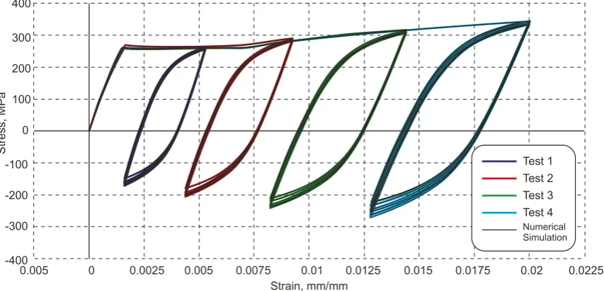
Fig. 1. Cyclic plasticity material response.
rate material behavior and fatigue lifetime prediction (Jahed et al., 2006; Parker and Underwood, 1999). Nevertheless, such research questions as the accurate material behavior modelling and fatigue lifetime prediction of autofrettaged components with high stress concentration locations are still open.
Conventional hydraulic autofrettage assumes application of overload pressure at ambient temperature. However, studies by Berman and Pai (1967, 1969) showed that application of autofrettage pressure at elevated temperature can provide some benefits over conventional ambient temperature autofrettage. Overload pressure in the case of elevated temperature autofrettage is significantly lower than that pressure for hydraulic autofrettage as inelastic creep strains are induced at a smaller level of stresses. This may be more favorable for the cases where the application of very high pressure in autofrettage assemblies may cause structural damage. That type of autofrettage can also provide a deeper level of compressive residual stresses compared to conventional autofrettage. In spite of the potential benefits of creep autofrettage, this problem has not got much attention sincethe first publications. This may be explained by a lack of the knowledge of the material properties under conditions of creep deformation and modelling techniques which are able to simulate creep compressive residual stresses. One of the objectives of this study is, therefore, to extend conventional hydraulic autofrettage to an elevated temperature autofrettage application with inducing creep strains.
Another problem for the autofrettage processes in general is prediction of the fatigue lifetime under the influence of compressive residual stresses. Despite the fact that compressive residual stresses can significantly improve the fatigue lifetime of high pressure components the mechanism of fatigue failure under the influence of compressive residual stresses is not always clear. The dominant part of the fatigue lifetime in components without compressive residual stresses is the crack initiation stage and as soon as a crack is initiated at the surface it immediately propagates inside a component causing fatigue failure. Time for the crack propagation in this case varies from tens to hundreds of cycles which is significantly less than crack initiation time. However, this may not be the case of components with high compressive residual stresses where an initiated crack can be arrested at some point of the propagation.
Volodymyr Okorokov et al. / Procedia Structural Integrity 5 (2017) 202–209 203
Available online at www.sciencedirect.com
Structural Integrity Procedia 00 (2017) 000–000
www.elsevier.com/locate/procedia
2nd International Conference on Structural Integrity, ICSI 2017, 4-7 September 2017, Funchal,
Madeira, Portugal
A comparative study between conventional and elevated temperature
creep autofrettage
Volodymyr Okorokov∗, Yevgen Gorash
University of Strathclyde, Technology&Innovation Centre, 99 George Street, Glasgow G1 1RD, Scotland, UK
Abstract
This paper presents a comparative study between conventional hydraulic and elevated temperature autofrettage. For modelling of both methods advanced plasticity and creep material models are used. The main governing equations for the models are presented
as well. A beneficial influence of compressive residual stresses induced by both methods is demonstrated on a benchmark problem of cross bored block. The effectiveness and applicability of the two methods are estimated by conduction of compressive residual
stress analysis and crack arrest modeling. Numerical simulation of the cyclic plasticity and creep problems are carried out by means of FEM in ANSYS Workbench with FORTRAN user-programmable subroutines for material model incorporating custom equations.
c
�2017 The Authors. Published by Elsevier B.V.
Peer-review under responsibility of the Scientific Committee of ICSI 2017.
Keywords:
Crack arrest, Creep autofrettage, Finite Element Analysis, Plasticity, Compressive residual stress
1. Introduction
Application of the autofrettage processes has become a useful tool of increasing the fatigue resistance for many high pressure components working in dynamic conditions. Nowadays, several types of autofrettage such as hydraulic, swage, thermal autofrettage and combination of autofrettage with shrink fitting technology are extensively used in different industries. This paper is mainly concentrated on the effect of hydraulic autofrettage which is applicable for a huge variety of high pressure parts with highly stressed locations due to sharp corners of bore intersections. The main idea of hydraulic autofrettage is to apply high pressure to the internal surface of a high pressure component in order to induce a plastic strain of required values. With unloading the elastic layers of a component start shrinking the plastically deformed layers thereby inducing compressive stresses. There have been numerous studies regard-ing to hydraulic autofrettage modellregard-ing startregard-ing from a simple analytical close solution (Adibi-Asl and Livieri, 2006; Wahi et al., 2011; Trojnacki and Krasi´nski, 2014) and ending with quite comprehensive models which include
accu-∗ Corresponding author. Tel.:+44-787-4275442 ; fax:+44-141-5520775. E-mail address:[email protected]
2452-3216 c�2017 The Authors. Published by Elsevier B.V.
Peer-review under responsibility of the Scientific Committee of ICSI 2017.
[image:2.544.60.487.76.282.2]2 V. Okorokov and Y. Gorash/Structural Integrity Procedia 00 (2017) 000–000
Fig. 1. Cyclic plasticity material response.
rate material behavior and fatigue lifetime prediction (Jahed et al., 2006; Parker and Underwood, 1999). Nevertheless, such research questions as the accurate material behavior modelling and fatigue lifetime prediction of autofrettaged components with high stress concentration locations are still open.
Conventional hydraulic autofrettage assumes application of overload pressure at ambient temperature. However, studies by Berman and Pai (1967, 1969) showed that application of autofrettage pressure at elevated temperature can provide some benefits over conventional ambient temperature autofrettage. Overload pressure in the case of elevated temperature autofrettage is significantly lower than that pressure for hydraulic autofrettage as inelastic creep strains are induced at a smaller level of stresses. This may be more favorable for the cases where the application of very high pressure in autofrettage assemblies may cause structural damage. That type of autofrettage can also provide a deeper level of compressive residual stresses compared to conventional autofrettage. In spite of the potential benefits of creep autofrettage, this problem has not got much attention sincethe first publications. This may be explained by a lack of the knowledge of the material properties under conditions of creep deformation and modelling techniques which are able to simulate creep compressive residual stresses. One of the objectives of this study is, therefore, to extend conventional hydraulic autofrettage to an elevated temperature autofrettage application with inducing creep strains.
Another problem for the autofrettage processes in general is prediction of the fatigue lifetime under the influence of compressive residual stresses. Despite the fact that compressive residual stresses can significantly improve the fatigue lifetime of high pressure components the mechanism of fatigue failure under the influence of compressive residual stresses is not always clear. The dominant part of the fatigue lifetime in components without compressive residual stresses is the crack initiation stage and as soon as a crack is initiated at the surface it immediately propagates inside a component causing fatigue failure. Time for the crack propagation in this case varies from tens to hundreds of cycles which is significantly less than crack initiation time. However, this may not be the case of components with high compressive residual stresses where an initiated crack can be arrested at some point of the propagation.
204 Volodymyr Okorokov et al. / Procedia Structural Integrity 5 (2017) 202–209
V. Okorokov and Y. Gorash/Structural Integrity Procedia 00 (2017) 000–000 3
If the crack arrest phenomenon is dominant in the fatigue life of autofrettaged part elevated temperature autofret-tage can provide higher fatigue life as the compressive residual stress field is deeper compared to the conventional autofrettage case. The compressive residual stress field isalso distributed more uniformly over a whole pressure part. Prediction of the crack arrest is a complex problem as it requires the knowledge not only of fracture material pa-rameters and crack propagation laws but an actual inelastic behavior of a material which is necessary for an accurate prediction of compressive residual stresses after autofrettage as well. In this work a new concept of modelling nonlin-ear material behavior under cyclic loading is combined with the crack propagation simulation techniques in order to predict the crack arrest phenomena in autofrettaged components.
2. Inelastic material modelling
The phenomenon of nonlinear inelastic deformation is in the base of autofrettage methods. Therefore, the knowl-edge of material nonlinear response under different loading and temperature conditions is of a high importance for accurate compressive residual stress field predictions. Despite the fact that such compressive residual stress induction methods as autofrettage have successfully been used over years the lack of both experimental data and theoretical modeling of the material inelastic response has still been limiting a huge potential of the autofrettage methods. This section presents results of the material testing and modelling concept for both conventional hydraulic autofrettage and elevated temperature creep autofrettage.
2.1. Cyclic plasticity testing
Conventional hydraulic autofrettage is usually performed by application of overload autofrettage pressure at am-bient temperature conditions. That means, in order to model this autofrettage process properly, the cyclic plasticity material response under ambient temperature should be obtained and simulated. A low carbon steel structural ad-dressed in this study is equivalent to a big international group of weldable, general-purpose, high-strength structural steels, which includes e.g.Grade 50 (A, B, C, D)from British Standard BS4360.
In order to investigate the cyclic and monotonic plasticity behavior, monotonic and cyclic tests with different loading programs have been conducted. The samples for mechanical testing have the following geometry parameters: total length – 140 mm; gauge length – 25 mm; grip section width – 20 mm; gauge section width – 12 mm; thickness – 6 mm. The testing has been done with the use of a 250 kN INSTRON servo-hydraulic testing machine under strain control with a total strain rate of 5·10−4s−1for both monotonic and cyclic loading. The strain has been measured by an extensometer with 10 mm in gauge length.
Figure 1 illustrates the results from the test with non-zeromean strain which induces the mean stress relaxation. This test is of a particular interest for the autofrettage methods as the test can show a realistic material response similar to that from the application of the autofrettage. This means that applying the overload pressure several times may lead to a deeper level of compressive residual stresses. This fact can be used in autofrettage procedures where increasing the autofrettage pressure is applied via a number of steps. It should be noted that a proper modelling of the effect of re-autofrettage is not possible without a plasticity model that can predict cyclic plasticity accurately.
2.2. Cyclic plasticity constitutive modelling
This study presents a constitutive model of cyclic plasticity which is based on the von Mises yield criterion. The yield surface is implemented as follows:
f =
3
2(S−X) : (S−X)−R−σ0, (1)
whereS– deviatoric stress tensor;X– back stress tensor;R - isotropic hardening variable;σ0 - initial size of the elastic domain.
The phenomena of cyclic softening and hardening suggest that stable hysteresis loops are achieved after a cycling under a fixed strain range. The present experimental observations show a strong dependence between stabilized stress peaks and strain ranges, thereby exhibiting non-Masing behaviour. In order to describe this type of the material
4 V. Okorokov and Y. Gorash/Structural Integrity Procedia 00 (2017) 000–000
0 25 50 75 100 125 150 175 200 225 250
0.0075 0.01 0.0125 0.015 0.0175 0.02
creep data - 49 MPa creep data - 73.6 MPa creep data - 98 MPa creep data - 122.6 MPa creep model - 49 MPa creep model - 73.6 MPa creep model - 98 MPa creep model - 122.6 MPa
Time, minutes
C
re
e
p s
tr
a
in
, m
m
/m
m
0.005
0.0025
0
Fig. 2. Creep curves for the structural steel SM50A at 550◦C fitted by the “Combined Time Hardening” creep model (7).
behaviour, Chaboche et al. (1979) proposed to use a new internal variable which introduces a dependence of the isotropic hardening asymptotic value on the plastic strain range. The memory surface is introduced as follows
F= (εp−ζ) (εp−ζ)−q, (2)
whereεp– plastic strain tensor;ζandq– the centre and the radius of the memory surface, respectively.
Nouailhas et al. (1985) and Ohno (1982) introduced a fading function into the variableqin order to provide a better agreement with experiments. Despite of the fact that these constitutive models are able to describe a cyclic stress-strain curve quite precisely, there are a few disadvantages of the model. The shape of the monotonic curve as well as the shape of each curve from a cyclic loading is completely determined by a single unified set of equations and parameters calibrated for a cyclic stress-strain curve. That means themonotonic curves for the first cycles will be different from experimental results. To overcome this problem and describe every stress-strain curve for cyclic loading starting from the monotonic curve up to the saturation of stresses, a new set of internal variables is introduced as:
˙ ¯ q=p
−p¯′−2¯q′ δ(Z) p˙ and p˙¯=p
−p¯′ δ(Z) p˙, (3)
whereq˙¯stand for the rate of strain amplitude that is attained in the previous step andp˙¯stand for the rate of accumulated plastic strain that is attained during all straining up to the end of the previous step;δ– Dirac delta function the argument of which is defined as follows:
Z =1 2
p−p′−sign(εeqp −ε¯eqp)(εeqp −ε′eqp) with εpeq=
2
3εp:εp. (4)
Other components of Eq. (4) are defined as follows
¯ q′=q¯(t
−τ), p′=p(t−τ), p¯′=p¯(t−τ) and ε′eqp=εeqp(t−τ), (5)
whereτis an infinitesimal time delay. The main feature of the above delay differential equations is that the Dirac function returns a required value exactly at the beginning of a new step. At other moments of time the Dirac function returns zero value and the variables remain unchanged during the plastic deformation. This allows the new variables to be constants on the current step of loading and change their value only at the beginning of the next step. The strain range dependence is then introduced into the constants in the isotropic hardening rule and kinematic hardening rule:
˙
R=b(Q−R)p˙ and X˙i=2
3ciγiε˙−γiXip˙, (6)
Volodymyr Okorokov et al. / Procedia Structural Integrity 5 (2017) 202–209 205 V. Okorokov and Y. Gorash/Structural Integrity Procedia 00 (2017) 000–000 3
If the crack arrest phenomenon is dominant in the fatigue life of autofrettaged part elevated temperature autofret-tage can provide higher fatigue life as the compressive residual stress field is deeper compared to the conventional autofrettage case. The compressive residual stress field isalso distributed more uniformly over a whole pressure part. Prediction of the crack arrest is a complex problem as it requires the knowledge not only of fracture material pa-rameters and crack propagation laws but an actual inelastic behavior of a material which is necessary for an accurate prediction of compressive residual stresses after autofrettage as well. In this work a new concept of modelling nonlin-ear material behavior under cyclic loading is combined with the crack propagation simulation techniques in order to predict the crack arrest phenomena in autofrettaged components.
2. Inelastic material modelling
The phenomenon of nonlinear inelastic deformation is in the base of autofrettage methods. Therefore, the knowl-edge of material nonlinear response under different loading and temperature conditions is of a high importance for accurate compressive residual stress field predictions. Despite the fact that such compressive residual stress induction methods as autofrettage have successfully been used over years the lack of both experimental data and theoretical modeling of the material inelastic response has still been limiting a huge potential of the autofrettage methods. This section presents results of the material testing and modelling concept for both conventional hydraulic autofrettage and elevated temperature creep autofrettage.
2.1. Cyclic plasticity testing
Conventional hydraulic autofrettage is usually performed by application of overload autofrettage pressure at am-bient temperature conditions. That means, in order to model this autofrettage process properly, the cyclic plasticity material response under ambient temperature should be obtained and simulated. A low carbon steel structural ad-dressed in this study is equivalent to a big international group of weldable, general-purpose, high-strength structural steels, which includes e.g.Grade 50 (A, B, C, D)from British Standard BS4360.
[image:4.544.110.435.75.251.2]In order to investigate the cyclic and monotonic plasticity behavior, monotonic and cyclic tests with different loading programs have been conducted. The samples for mechanical testing have the following geometry parameters: total length – 140 mm; gauge length – 25 mm; grip section width – 20 mm; gauge section width – 12 mm; thickness – 6 mm. The testing has been done with the use of a 250 kN INSTRON servo-hydraulic testing machine under strain control with a total strain rate of 5·10−4s−1for both monotonic and cyclic loading. The strain has been measured by an extensometer with 10 mm in gauge length.
Figure 1 illustrates the results from the test with non-zeromean strain which induces the mean stress relaxation. This test is of a particular interest for the autofrettage methods as the test can show a realistic material response similar to that from the application of the autofrettage. This means that applying the overload pressure several times may lead to a deeper level of compressive residual stresses. This fact can be used in autofrettage procedures where increasing the autofrettage pressure is applied via a number of steps. It should be noted that a proper modelling of the effect of re-autofrettage is not possible without a plasticity model that can predict cyclic plasticity accurately.
2.2. Cyclic plasticity constitutive modelling
This study presents a constitutive model of cyclic plasticity which is based on the von Mises yield criterion. The yield surface is implemented as follows:
f =
3
2(S−X) : (S−X)−R−σ0, (1)
whereS– deviatoric stress tensor;X– back stress tensor;R- isotropic hardening variable;σ0 - initial size of the elastic domain.
The phenomena of cyclic softening and hardening suggest that stable hysteresis loops are achieved after a cycling under a fixed strain range. The present experimental observations show a strong dependence between stabilized stress peaks and strain ranges, thereby exhibiting non-Masing behaviour. In order to describe this type of the material
4 V. Okorokov and Y. Gorash/Structural Integrity Procedia 00 (2017) 000–000
0 25 50 75 100 125 150 175 200 225 250
0.0075 0.01 0.0125 0.015 0.0175 0.02
creep data - 49 MPa creep data - 73.6 MPa creep data - 98 MPa creep data - 122.6 MPa creep model - 49 MPa creep model - 73.6 MPa creep model - 98 MPa creep model - 122.6 MPa
Time, minutes
C
re
e
p s
tr
a
in
, m
m
/m
m
0.005
0.0025
[image:4.544.52.481.514.578.2]0
Fig. 2. Creep curves for the structural steel SM50A at 550◦C fitted by the “Combined Time Hardening” creep model (7).
behaviour, Chaboche et al. (1979) proposed to use a new internal variable which introduces a dependence of the isotropic hardening asymptotic value on the plastic strain range. The memory surface is introduced as follows
F= (εp−ζ) (εp−ζ)−q, (2)
whereεp– plastic strain tensor;ζandq– the centre and the radius of the memory surface, respectively.
Nouailhas et al. (1985) and Ohno (1982) introduced a fading function into the variableqin order to provide a better agreement with experiments. Despite of the fact that these constitutive models are able to describe a cyclic stress-strain curve quite precisely, there are a few disadvantages of the model. The shape of the monotonic curve as well as the shape of each curve from a cyclic loading is completely determined by a single unified set of equations and parameters calibrated for a cyclic stress-strain curve. That means themonotonic curves for the first cycles will be different from experimental results. To overcome this problem and describe every stress-strain curve for cyclic loading starting from the monotonic curve up to the saturation of stresses, a new set of internal variables is introduced as:
˙ ¯ q=p
−p¯′−2¯q′ δ(Z) p˙ and p˙¯=p
−p¯′ δ(Z) p˙, (3)
whereq˙¯stand for the rate of strain amplitude that is attained in the previous step andp˙¯stand for the rate of accumulated plastic strain that is attained during all straining up to the end of the previous step;δ– Dirac delta function the argument of which is defined as follows:
Z= 1 2
p−p′−sign(εpeq−ε¯peq)(εeqp −ε′eqp) with εeqp =
2
3εp:εp. (4)
Other components of Eq. (4) are defined as follows
¯ q′=q¯(t
−τ), p′=p(t−τ), p¯′=p¯(t−τ) and ε′eqp=εeqp(t−τ), (5)
whereτis an infinitesimal time delay. The main feature of the above delay differential equations is that the Dirac function returns a required value exactly at the beginning of a new step. At other moments of time the Dirac function returns zero value and the variables remain unchanged during the plastic deformation. This allows the new variables to be constants on the current step of loading and change their value only at the beginning of the next step. The strain range dependence is then introduced into the constants in the isotropic hardening rule and kinematic hardening rule:
˙
R=b(Q−R)p˙ and X˙i= 2
3ciγiε˙−γiXip˙, (6)
206 Volodymyr Okorokov et al. / Procedia Structural Integrity 5 (2017) 202–209
V. Okorokov and Y. Gorash/Structural Integrity Procedia 00 (2017) 000–000 5
-90.9 -83.9 -76.8 -69.8 -62.8 -55.7 -48.7 -41.6 -34.6 -27.6 -20.5 -13.5 -6.42 0.63
-90.9 -83.8 -76.7 -69.6 -62.6 -55.5 -48.4 -41.3 -34.3 -27.2 -20.1 -13.0 -5.97 1.11
a
b
Fig. 3. Compressive residual stress field for conventional autofrettage (a) vs compressive residual stress field for creep autofrettage (b).
2.3. Creep data and model
For the purpose of basic feasibility study, the creep constitutive model with constants fitted to available creep test data are all taken from Kodur and Dwaikat (2010). Since performing creep tests at high temperature is very complex and time consuming, at starting stage of research a basic “Combined Time Hardening” creep model is sufficient enough for getting an idea on efficiency of alternative autofrettage approach. This model was selected by Kodur and Dwaikat (2010) from 13 standard creep models available in ANSYS, because it can model both the primary and secondary creep, and is capable of predicting creep strain regardless of any coupling between time and either stress or temperature of steel. The available creep curves at 550◦C from Nippon Steel Corporation for the structural steel SM50A, which is close to the steel addressed in this work, were fitted as shown in Fig. 2 by the following equation:
εcr=C1σ
C2tC3+1e−C4/T
C3+1 +C5σ
C6t e−C7/T, (7)
where the values of creep constantsC1−C7are provided by Kodur and Dwaikat (2010).
3. Conventional vs. elevated temperature autofrettage modelling
This section presents an example of the autofrettage simulation for a high pressure component. The high pressure component is presented by a cross-bored steel block specimen proposed by Badr et al. (2000) with material parameters found for a low carbon steel. High pressure parts usually experience cyclic dynamic loading conditions during the service life. Fatigue is, therefore, the main failure mechanism for such high pressure components. Investigation of broken pressure parts with bore intersection shows that the most dangerous location in the part is the sharp corner of the bore intersection. Introduction of the compressive residual stresses by the autofrettage methods into this area can significantly increase fatigue resistance of a high pressure part.
One of the objectives in this study is to show the difference between conventional hydraulic autofrettage and ele-vated temperature creep autofrettage and define the optimalconditions of applicability for both methods. Conventional hydraulic autofrettage is simulated by applying a high pressure to the internal surface of a high pressure component in order to induce a plastic strain of required values. With unloading the elastic layers of a component start shrink-ing the plastically deformed layers thereby inducshrink-ing compressive stresses. The idea of elevated temperature creep autofrettage is similar to the conventional one except for the high temperature that is applied together with autofret-tage pressure. The numerical simulation is implemented by means of FEM with the use of ANSYS Workbench. The proposed plasticity and creep models are incorporated into ANSYS Workbench by the means of User Programmable Features (UPF), where user implements custom equations and solving algorithms.
6 V. Okorokov and Y. Gorash/Structural Integrity Procedia 00 (2017) 000–000
-100 -80 -60 -40 -20 0 20
0 5 10 15 20 25 30 35 40
Co
m
p
re
ssiv
e
st
re
ss,
M
P
a
Path length, mm
High temperature creep autofrettage Conventional hydraulic autofrettage
1
[image:5.544.70.469.76.245.2]2
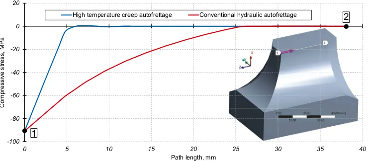
Fig. 4. Comparison of compressive residual stresses along the bore.
Figure 3 demonstrates the result of the autofrettage simulation by both methods. It has been found that in order to induce the magnitude of compressive residual stress of−90.9 MPa in the corner of the bore intersection the pressure of 27.9 MPa is required. At the same time only 11.5 MPa of pressure is enough to induce the same magnitude of compressive residual stress by elevated temperature creep autofrettage. The distribution of the compressive residual stresses over the distance from the corner is also more favourable in the case of creep autofrettage. It is seen from the Fig. 4 that the compressive residual stresses induced by conventional hydraulic autofrettage quickly disappear just after a few millimetres away from the bore intersection corner. In the case of elevated temperature creep autofrettage the compressive residual stresses are distributed more uniformly over the whole bores. This shows significant benefit of creep autofrettage over conventional autofrettage as this distribution of the compressive residual stresses can provide fatigue crack resistance not only in the corner of the bore intersection but over other locations as well.
However, it should be noted that elevated temperature autofrettage has advantages only within a certain lower pressure range. It is obvious that increasing the autofrettage pressure in conventional autofrettage can give much higher magnitude of the compressive residual stresses. Nevertheless, in the low pressure range creep autofrettage provides compressive residual stresses that cannot be attained by conventional autofrettage at all. As it was pointed out before elevated temperature creep autofrettage can be efficiently applied to high pressure parts where application of extremely high pressure required by conventional autofrettage is not attainable or may cause structural damage to the assembly.
4. Modelling of the crack arrest phenomenon
Volodymyr Okorokov et al. / Procedia Structural Integrity 5 (2017) 202–209 207 V. Okorokov and Y. Gorash/Structural Integrity Procedia 00 (2017) 000–000 5
-90.9 -83.9 -76.8 -69.8 -62.8 -55.7 -48.7 -41.6 -34.6 -27.6 -20.5 -13.5 -6.42 0.63
-90.9 -83.8 -76.7 -69.6 -62.6 -55.5 -48.4 -41.3 -34.3 -27.2 -20.1 -13.0 -5.97 1.11
a
b
Fig. 3. Compressive residual stress field for conventional autofrettage (a) vs compressive residual stress field for creep autofrettage (b).
2.3. Creep data and model
For the purpose of basic feasibility study, the creep constitutive model with constants fitted to available creep test data are all taken from Kodur and Dwaikat (2010). Since performing creep tests at high temperature is very complex and time consuming, at starting stage of research a basic “Combined Time Hardening” creep model is sufficient enough for getting an idea on efficiency of alternative autofrettage approach. This model was selected by Kodur and Dwaikat (2010) from 13 standard creep models available in ANSYS, because it can model both the primary and secondary creep, and is capable of predicting creep strain regardless of any coupling between time and either stress or temperature of steel. The available creep curves at 550◦C from Nippon Steel Corporation for the structural steel SM50A, which is close to the steel addressed in this work, were fitted as shown in Fig. 2 by the following equation:
εcr=C1σ
C2tC3+1e−C4/T
C3+1 +C5σ
C6t e−C7/T, (7)
where the values of creep constantsC1−C7are provided by Kodur and Dwaikat (2010).
3. Conventional vs. elevated temperature autofrettage modelling
This section presents an example of the autofrettage simulation for a high pressure component. The high pressure component is presented by a cross-bored steel block specimen proposed by Badr et al. (2000) with material parameters found for a low carbon steel. High pressure parts usually experience cyclic dynamic loading conditions during the service life. Fatigue is, therefore, the main failure mechanism for such high pressure components. Investigation of broken pressure parts with bore intersection shows that the most dangerous location in the part is the sharp corner of the bore intersection. Introduction of the compressive residual stresses by the autofrettage methods into this area can significantly increase fatigue resistance of a high pressure part.
One of the objectives in this study is to show the difference between conventional hydraulic autofrettage and ele-vated temperature creep autofrettage and define the optimalconditions of applicability for both methods. Conventional hydraulic autofrettage is simulated by applying a high pressure to the internal surface of a high pressure component in order to induce a plastic strain of required values. With unloading the elastic layers of a component start shrink-ing the plastically deformed layers thereby inducshrink-ing compressive stresses. The idea of elevated temperature creep autofrettage is similar to the conventional one except for the high temperature that is applied together with autofret-tage pressure. The numerical simulation is implemented by means of FEM with the use of ANSYS Workbench. The proposed plasticity and creep models are incorporated into ANSYS Workbench by the means of User Programmable Features (UPF), where user implements custom equations and solving algorithms.
6 V. Okorokov and Y. Gorash/Structural Integrity Procedia 00 (2017) 000–000
-100 -80 -60 -40 -20 0 20
0 5 10 15 20 25 30 35 40
Co
m
p
re
ssiv
e
st
re
ss,
M
P
a
Path length, mm
High temperature creep autofrettage Conventional hydraulic autofrettage
1
[image:6.544.88.460.76.238.2]2
Fig. 4. Comparison of compressive residual stresses along the bore.
Figure 3 demonstrates the result of the autofrettage simulation by both methods. It has been found that in order to induce the magnitude of compressive residual stress of−90.9 MPa in the corner of the bore intersection the pressure of 27.9 MPa is required. At the same time only 11.5 MPa of pressure is enough to induce the same magnitude of compressive residual stress by elevated temperature creep autofrettage. The distribution of the compressive residual stresses over the distance from the corner is also more favourable in the case of creep autofrettage. It is seen from the Fig. 4 that the compressive residual stresses induced by conventional hydraulic autofrettage quickly disappear just after a few millimetres away from the bore intersection corner. In the case of elevated temperature creep autofrettage the compressive residual stresses are distributed more uniformly over the whole bores. This shows significant benefit of creep autofrettage over conventional autofrettage as this distribution of the compressive residual stresses can provide fatigue crack resistance not only in the corner of the bore intersection but over other locations as well.
However, it should be noted that elevated temperature autofrettage has advantages only within a certain lower pressure range. It is obvious that increasing the autofrettage pressure in conventional autofrettage can give much higher magnitude of the compressive residual stresses. Nevertheless, in the low pressure range creep autofrettage provides compressive residual stresses that cannot be attained by conventional autofrettage at all. As it was pointed out before elevated temperature creep autofrettage can be efficiently applied to high pressure parts where application of extremely high pressure required by conventional autofrettage is not attainable or may cause structural damage to the assembly.
4. Modelling of the crack arrest phenomenon
208 Volodymyr Okorokov et al. / Procedia Structural Integrity 5 (2017) 202–209
V. Okorokov and Y. Gorash/Structural Integrity Procedia 00 (2017) 000–000 7
0 5 10 15 20 25
0 1 2 3 6 7 8 9 10 11 12
St
res
s
Int
enc
ity
R
ang
e,
M
Pa*
m
^0.
5
Crack Length, mm Convent. Autofrettage, Service Pressure = 10 MPa Convent. Autofrettage, Service Pressure = 15 MPa Creep Autofrettage, Service Pressure = 13 MPa Creep Autofrettage, Service Pressure = 19 MPa Fatigue crack growth threshold
[image:7.544.65.480.78.226.2]4 5
Fig. 5. Stress intensity calculations for conventional and creep autofrettage.
In order to calculate the total load required for crack initiation and propagation application of fracture mechanics approaches is required. In this study the concept of crack closure is used. According to this the effective stress intensity factor range is defined as:
∆Ke f f =Kmax−Kop, (8)
whereKmax– stress intensity factor calculated at maximum load;Kop– stress intensity factor calculated when a crack
starts to open; and a crack propagates when the following condition is fulfilled:
∆Ke f f >∆Ktr (9)
where ∆Ktr – effective fatigue crack propagation threshold. For low carbon steels this value can be estimated as 3 [MPa√m]. That condition is essentially means that if the effective stress intensity factor range is less than the effective crack propagation threshold a crack does not propagate.
One of the objectives in this study is to compare crack arrest analysis for conventional hydraulic autofrettage and for elevated temperature creep autofrettage. As the stress analysis for creep autofrettage has shown a deeper level of compressive residual stresses for the same magnitude of compressive residual stress at the corner of intersected bores a crack initiated at the corner is expected to be arrested at longer length in the case of creep autofrettage compared to conventional autofrettage. In order to conduct the crack arrest analysis an elliptical crack is introduced into the pressure part in the corner of the bore intersection with faces perpendicular to the maximum principal stress direction. Propagation of the crack is simulated by nodal release method (Anderson, 2005).
The main steps of the crack arrest analysis is defined as follows: 1. Defining initial crack length.
2. Applying service pressure to the pressure part. At this stageKmaxandKopare determined using weight function
method (Anderson, 2005).
3. If the condition (9) is fulfilled the crack propagates and a new crack front is defined. If the condition (9) is not fulfilled the crack is arrested. The pressure value from the step 2 is then defined as the fatigue limit.
4. Unloading and releasing nodes of crack faces according to the new crack front and repeating the steps 2 and 3. Figure 5 demonstrates the results of the crack arrest analysis for the pressure part autofrettaged by using both conventional and elevated temperature creep autofrettage. Both methods show similar results with regards to the arrested crack. The crack is allowed to start propagating from the bore intersection. However, with propagating inside the field of high compressive residual stresses the effective crack intensity factor ranges slow down reaching the value of effective fatigue crack propagation threshold. That means the crack is arrested and can only be forced to propagate by increasing the service pressure. The difference between the two methods is that with the use of creep autofrettage the crack is arrested for a longer length and under a higher pressure. Therefore, the pressure part has a higher fatigue limit when elevated temperature autofrettage is used.
8 V. Okorokov and Y. Gorash/Structural Integrity Procedia 00 (2017) 000–000
5. Conclusions
This paper presents the comparative study between conventional hydraulic autofrettage and elevated temperature creep autofrettage. Advanced plasticity and creep material modelling is used for simulation of both autofrettage meth-ods. In order to analyze the effectiveness of the two autofrettage methods the compressive residual stress analysis together with crack arrest analysis are conducted.
Elevated temperature creep autofrettage has advantages over conventional hydraulic autofrettage in the low pres-sure autofrettage range. This is explained by the fact that the material does not have yield stress during creep defor-mation, so that creep strains are developed at any level of stress. The results show that creep autofrettage can induce a high magnitude of compressive residual stresses by applying pressure of values similar to working conditions. At this pressure range conventional autofrettage is not applicable at all. This makes creep autofrettage very attractive for the applications where high autofrettage pressure can cause structural damage.
Conventional autofrettage shows a very high compressive residual stress magnitude in the bore intersection location of a high pressure part. However, these stresses decrease rapidly moving away from the stress concentration. Elevated temperature creep autofrettage can provide a deeper level of compressive residual stresses with a high magnitude of these stresses even far away from the stress concentration. This allows a longer crack to be arrested in the pressure part under a higher service pressure compared to conventional autofrettage. Potentially, the biggest benefit of the two autofrettage methods can be attained by its combination. In this case a very high magnitude of compressive residual stresses can be induced in the bore intersection by conventional autofrettage. Whereas elevated temperature creep autofrettage can provide a high level of compressive residual stresses away from the stress concentration.
Acknowledgements
This study was implemented in the frames of H2020 European Industrial Doctorate project (ref. 643159) titled “Advanced Pump Engineering for Severe Applications” (APESA – www.apesaproject.eu) initiated by the University of Strathclyde and Weir Minerals.
References
Adibi-Asl, R., Livieri, P., 2006. Analytical approach in autofrettaged spherical pressure vessels considering the bauschinger effect. J. of Pressure
Vessel Technology 129(3), 411–419.
Anderson, T.L., 2005. Fracture Mechanics: Fundamentals and Applications. 3rd ed., CRC Press, Boca Raton, FL.
Badr, E., Sorem, J., Tipton, S., 2000. Evaluation of the autofrettage effect on fatigue lives of steel blocks with crossbores using a statistical and a
strain-based method. J. of Testing and Evaluation 28(3), 181–188.
Berman, I., Pai, D.H., 1967. Elevated temperature autofrettage. J. of Engineering for Power 89(3), 369–375.
Berman, I., Pai, D.H., 1969. Creep autofrettage. U.S. Patent 3,438,114. URL:http://www.google.co.uk/patents/US3438114.
Chaboche, J.-L., Dang Van, K., Cordier, G., 1979. Modelization of the strain memory effect on the cyclic hardening of 316 stainless steel, in: Trans.
5th Int. Conf. on Structural Mechanics in Reactor Technology. IASMiRT, Berlin, Germany. number L11/3 in SMiRT5, pp. 1–10.
Herz, E., Hertel, O., Vormwald, M., 2011. Numerical simulation of plasticity induced fatigue crack opening and closure for autofrettaged intersect-ing holes. Engineerintersect-ing Fracture Mechanics 78(3), 559–572.
Jahed, H., Farshi, B., Hosseini, M., 2006. Fatigue life prediction of autofrettage tubes using actual material behaviour. Int. J. of Pressure Vessels & Piping 83(10), 749–755.
Kodur, V.K.R., Dwaikat, M.M.S., 2010. Effect of high temperature creep on the fire response of restrained steel beams. Materials & Structures
43(10), 1327–1341.
Nouailhas, D., Cailletaud, G., Policella, H., Marquis, D., Dufailly, J., Lieurade, H., Ribes, A., Bollinger, E., 1985. On the description of cyclic hardening and initial cold working. Engineering Fracture Mechanics 21(4), 887–895.
Ohno, N., 1982. A constitutive model of cyclic plasticity with a nonhardening strain region. J. of Applied Mechanics 49(4), 721–727.
Parker, A.P., Underwood, J.H., 1999. Influence of bauschinger effect on residual stress and fatigue lifetimes in autofrettaged thick-walled cylinders,
in: Panontin, T.L., Sheppard, S.D. (Eds.), Fatigue and Fracture Mechanics: vol. 29, ASTM STP 1332. American Society for Testing and Materials, West Conshohocken, PA, USA, pp. 565–583.
Taylor, D., 2007. The Theory of Critical Distances: A New Perspective in Fracture Mechanics. Elsevier Science Ltd, Oxford.
Trojnacki, A., Krasi´nski, M., 2014. Numerical verification of analytical solution for autofrettaged high-pressure vessels. J. of Theoretical & Applied
Mechanics 52(3), 731–744.
Wahi, N., Ayob, A., Kabashi Elbasheer, M., 2011. Effect of optimum autofrettage on pressure limits of thick-walled cylinder. Int. J. of
Volodymyr Okorokov et al. / Procedia Structural Integrity 5 (2017) 202–209 209 V. Okorokov and Y. Gorash/Structural Integrity Procedia 00 (2017) 000–000 7
0 5 10 15 20 25
0 1 2 3 6 7 8 9 10 11 12
St
res
s
Int
enc
ity
R
ang
e,
M
Pa*
m
^0.
5
Crack Length, mm Convent. Autofrettage, Service Pressure = 10 MPa Convent. Autofrettage, Service Pressure = 15 MPa Creep Autofrettage, Service Pressure = 13 MPa Creep Autofrettage, Service Pressure = 19 MPa Fatigue crack growth threshold
4 5
Fig. 5. Stress intensity calculations for conventional and creep autofrettage.
In order to calculate the total load required for crack initiation and propagation application of fracture mechanics approaches is required. In this study the concept of crack closure is used. According to this the effective stress intensity factor range is defined as:
∆Ke f f =Kmax−Kop, (8)
whereKmax– stress intensity factor calculated at maximum load;Kop– stress intensity factor calculated when a crack
starts to open; and a crack propagates when the following condition is fulfilled:
∆Ke f f >∆Ktr (9)
where∆Ktr – effective fatigue crack propagation threshold. For low carbon steels this value can be estimated as 3 [MPa√m]. That condition is essentially means that if the effective stress intensity factor range is less than the effective crack propagation threshold a crack does not propagate.
One of the objectives in this study is to compare crack arrest analysis for conventional hydraulic autofrettage and for elevated temperature creep autofrettage. As the stress analysis for creep autofrettage has shown a deeper level of compressive residual stresses for the same magnitude of compressive residual stress at the corner of intersected bores a crack initiated at the corner is expected to be arrested at longer length in the case of creep autofrettage compared to conventional autofrettage. In order to conduct the crack arrest analysis an elliptical crack is introduced into the pressure part in the corner of the bore intersection with faces perpendicular to the maximum principal stress direction. Propagation of the crack is simulated by nodal release method (Anderson, 2005).
The main steps of the crack arrest analysis is defined as follows: 1. Defining initial crack length.
2. Applying service pressure to the pressure part. At this stageKmaxandKopare determined using weight function
method (Anderson, 2005).
3. If the condition (9) is fulfilled the crack propagates and a new crack front is defined. If the condition (9) is not fulfilled the crack is arrested. The pressure value from the step 2 is then defined as the fatigue limit.
4. Unloading and releasing nodes of crack faces according to the new crack front and repeating the steps 2 and 3. Figure 5 demonstrates the results of the crack arrest analysis for the pressure part autofrettaged by using both conventional and elevated temperature creep autofrettage. Both methods show similar results with regards to the arrested crack. The crack is allowed to start propagating from the bore intersection. However, with propagating inside the field of high compressive residual stresses the effective crack intensity factor ranges slow down reaching the value of effective fatigue crack propagation threshold. That means the crack is arrested and can only be forced to propagate by increasing the service pressure. The difference between the two methods is that with the use of creep autofrettage the crack is arrested for a longer length and under a higher pressure. Therefore, the pressure part has a higher fatigue limit when elevated temperature autofrettage is used.
8 V. Okorokov and Y. Gorash/Structural Integrity Procedia 00 (2017) 000–000
5. Conclusions
This paper presents the comparative study between conventional hydraulic autofrettage and elevated temperature creep autofrettage. Advanced plasticity and creep material modelling is used for simulation of both autofrettage meth-ods. In order to analyze the effectiveness of the two autofrettage methods the compressive residual stress analysis together with crack arrest analysis are conducted.
Elevated temperature creep autofrettage has advantages over conventional hydraulic autofrettage in the low pres-sure autofrettage range. This is explained by the fact that the material does not have yield stress during creep defor-mation, so that creep strains are developed at any level of stress. The results show that creep autofrettage can induce a high magnitude of compressive residual stresses by applying pressure of values similar to working conditions. At this pressure range conventional autofrettage is not applicable at all. This makes creep autofrettage very attractive for the applications where high autofrettage pressure can cause structural damage.
Conventional autofrettage shows a very high compressive residual stress magnitude in the bore intersection location of a high pressure part. However, these stresses decrease rapidly moving away from the stress concentration. Elevated temperature creep autofrettage can provide a deeper level of compressive residual stresses with a high magnitude of these stresses even far away from the stress concentration. This allows a longer crack to be arrested in the pressure part under a higher service pressure compared to conventional autofrettage. Potentially, the biggest benefit of the two autofrettage methods can be attained by its combination. In this case a very high magnitude of compressive residual stresses can be induced in the bore intersection by conventional autofrettage. Whereas elevated temperature creep autofrettage can provide a high level of compressive residual stresses away from the stress concentration.
Acknowledgements
This study was implemented in the frames of H2020 European Industrial Doctorate project (ref. 643159) titled “Advanced Pump Engineering for Severe Applications” (APESA – www.apesaproject.eu) initiated by the University of Strathclyde and Weir Minerals.
References
Adibi-Asl, R., Livieri, P., 2006. Analytical approach in autofrettaged spherical pressure vessels considering the bauschinger effect. J. of Pressure
Vessel Technology 129(3), 411–419.
Anderson, T.L., 2005. Fracture Mechanics: Fundamentals and Applications. 3rd ed., CRC Press, Boca Raton, FL.
Badr, E., Sorem, J., Tipton, S., 2000. Evaluation of the autofrettage effect on fatigue lives of steel blocks with crossbores using a statistical and a
strain-based method. J. of Testing and Evaluation 28(3), 181–188.
Berman, I., Pai, D.H., 1967. Elevated temperature autofrettage. J. of Engineering for Power 89(3), 369–375.
Berman, I., Pai, D.H., 1969. Creep autofrettage. U.S. Patent 3,438,114. URL:http://www.google.co.uk/patents/US3438114.
Chaboche, J.-L., Dang Van, K., Cordier, G., 1979. Modelization of the strain memory effect on the cyclic hardening of 316 stainless steel, in: Trans.
5th Int. Conf. on Structural Mechanics in Reactor Technology. IASMiRT, Berlin, Germany. number L11/3 in SMiRT5, pp. 1–10.
Herz, E., Hertel, O., Vormwald, M., 2011. Numerical simulation of plasticity induced fatigue crack opening and closure for autofrettaged intersect-ing holes. Engineerintersect-ing Fracture Mechanics 78(3), 559–572.
Jahed, H., Farshi, B., Hosseini, M., 2006. Fatigue life prediction of autofrettage tubes using actual material behaviour. Int. J. of Pressure Vessels & Piping 83(10), 749–755.
Kodur, V.K.R., Dwaikat, M.M.S., 2010. Effect of high temperature creep on the fire response of restrained steel beams. Materials & Structures
43(10), 1327–1341.
Nouailhas, D., Cailletaud, G., Policella, H., Marquis, D., Dufailly, J., Lieurade, H., Ribes, A., Bollinger, E., 1985. On the description of cyclic hardening and initial cold working. Engineering Fracture Mechanics 21(4), 887–895.
Ohno, N., 1982. A constitutive model of cyclic plasticity with a nonhardening strain region. J. of Applied Mechanics 49(4), 721–727.
Parker, A.P., Underwood, J.H., 1999. Influence of bauschinger effect on residual stress and fatigue lifetimes in autofrettaged thick-walled cylinders,
in: Panontin, T.L., Sheppard, S.D. (Eds.), Fatigue and Fracture Mechanics: vol. 29, ASTM STP 1332. American Society for Testing and Materials, West Conshohocken, PA, USA, pp. 565–583.
Taylor, D., 2007. The Theory of Critical Distances: A New Perspective in Fracture Mechanics. Elsevier Science Ltd, Oxford.
Trojnacki, A., Krasi´nski, M., 2014. Numerical verification of analytical solution for autofrettaged high-pressure vessels. J. of Theoretical & Applied
Mechanics 52(3), 731–744.
Wahi, N., Ayob, A., Kabashi Elbasheer, M., 2011. Effect of optimum autofrettage on pressure limits of thick-walled cylinder. Int. J. of