Hybrid specimens eliminating stress concentrations in tensile and
compressive testing of unidirectional composites
Gergely Czél
a,b,⇑, Meisam Jalalvand
b, Michael R. Wisnom
baMTA–BME Research Group for Composite Science and Technology, Budapest University of Technology and Economics, M}
uegyetem rkp. 3, H-1111 Budapest, Hungary b
Advanced Composites Centre for Innovation and Science, University of Bristol, Queen’s Building, BS8 1TR Bristol, United Kingdom
a r t i c l e i n f o
Article history:
Received 10 July 2015
Received in revised form 22 July 2016 Accepted 25 July 2016
Available online 30 July 2016
Keywords:
A. Carbon fibres B. Delamination B. Fragmentation D. Mechanical testing
a b s t r a c t
Two novel approaches are proposed for elimination of stress concentrations in tensile and compressive testing of unidirectional carbon/epoxy composites. An interlayer hybrid specimen type is proposed for tensile testing. The presented finite element study indicated that the outer continuous glass/epoxy plies suppress the stress concentrations at the grips and protect the central carbon/epoxy plies from premature failure, eliminating the need for end-tabs. The test results confirmed the benefits of the hybrid specimens by generating consistent gauge-section failures in tension. The developed hybrid four point bending spec-imen type and strain evaluation method were verified and applied successfully to determine the com-pressive failure strain of three different grade carbon/epoxy composite prepregs. Stable failure and fragmentation of the high and ultra-high modulus unidirectional carbon/epoxy plies were reported. The high strength carbon/epoxy plies exhibited catastrophic failure at a significantly higher compressive strain than normally observed.
Ó2016 The Authors. Published by Elsevier Ltd. This is an open access article under the CC BY license (http:// creativecommons.org/licenses/by/4.0/).
1. Introduction
Carbon fibre reinforced composites offer outstanding strength and stiffness, low density, corrosion resistance and therefore they are more and more considered for advanced, lightweight structural applications such as aero-structures, spacecraft, motorsports and high specification sport equipment. However, their low failure strain and brittle failure character not only limit their adoption in safety-critical applications such as automotive or construction, but also makes their mechanical testing challenging.
The most basic material properties of a unidirectional (UD) car-bon/epoxy composite are its elastic modulus, failure strain and strength, which are essential input parameters for design and mod-elling, but usually problematic to measure accurately. Even if the conventional non-hybrid specimens are laid-up, cured, machined and gripped carefully, they usually fail prematurely around the grips at strains significantly lower than the ultimate strain of the fibres. The reduction in the measured tensile failure strain is mainly attributed to the stress concentrations at the edge of the
end-tabs due to localised stress-transfer from the tabs to the specimen.
The specimens recommended by the ISO 527-5[1]and ASTM D5083–10 [2] standards require prismatic end-tabs and ASTM D3039/D3039M–08[3]requires special tapered end-tabs to pro-tect the specimen surface from the serrated grip faces. The end-tabs are useful, but they still generate stress concentrations where they terminate and the specimens tend to fracture first in this region. Careful design, especially tapering of the end-tabs, use of thick, ductile adhesive layers and precise fabrication can reduce the stress concentrations[4,5], but they cannot be fully eliminated even with this significant extra effort and cost. De Baere et al.[6]
reported up to 12% and 27% stress concentration for tapered and prismatic end tabs respectively in UD carbon fibre reinforced spec-imens with glass/epoxy tabs modelling only the composite parts without the adhesive layer. Wisnom et al.[7–9]developed special UD tensile specimens which were tapered using extra, chamfered plies in the gripping regions to make the ends thicker and contin-uous plies running along the whole specimen. Consistent gauge section failures and high ultimate strength and strain values were reported. For example tapered unidirectional carbon/epoxy speci-mens gave strengths 14% higher than with end-tabbed straight sided coupons, and 21% higher than those given in the manufac-turer’s data sheet [9]. However the complicated manufacturing process of the special tapered specimens is not ideal for standard
http://dx.doi.org/10.1016/j.compositesa.2016.07.021
1359-835X/Ó2016 The Authors. Published by Elsevier Ltd.
This is an open access article under the CC BY license (http://creativecommons.org/licenses/by/4.0/).
⇑Corresponding author at: MTA–BME Research Group for Composite Science and Technology, Budapest University of Technology and Economics, M}uegyetem rkp. 3, H-1111 Budapest, Hungary.
E-mail address:czel@pt.bme.hu(G. Czél).
Contents lists available atScienceDirect
Composites: Part A
material testing. A simple and practical approach to make the most of conventional UD composite tests is to use the thinnest possible specimens, which are less affected by stress concentrations because their failure loads are lower, therefore more easily trans-ferred from the end-tabs to the gauge section. Thin specimens also require lower grip pressures, which increases the probability of gauge section failure. Although the knock-down of the measured ultimate properties may be reduced with thin specimens, they are still affected by the stress concentrations.
Our first aim is to propose a novel approach to suppress the end-tab stress concentrations by using UD glass/carbon interlayer hybrid composite specimens avoiding the need to optimise the gripping conditions for tensile testing. Interlayer hybrids have shown good potential for creating gradual [10–13] and stable pseudo-ductile failure[14–18]in high performance UD compos-ites, but in the current study they are designed to show a single fracture of the carbon layer followed by catastrophic delamination within the gauge section to produce a clear and detectable event (i.e. a significant stress drop) in the stress-strain response, which can be exploited for carbon/epoxy layer failure strain detection. This approach offers the further advantage of eliminating the need for end tabs altogether, since the surface glass layers protect the carbon plies from the grips.
Compressive testing of UD composites is even more demanding, because the specimens need to be perfectly aligned and supported against buckling. Several test fixture designs and corresponding specimen types have evolved since the early seventies. The main approaches for direct compression testing are shear-loaded specimens with short, unsupported gauge sections according to ASTM D3410/D3410M–03 [19] and end-loaded specimens with anti-buckling support as specified in ASTM D695–10[20]. Both test setups have advantages and shortcomings, therefore combined end- and shear loading fixtures were developed in the mid-nineties. The so called Imperial College rig[21]was presented first in 1994 and then the Combined Loading Compression (CLC) fixture
[22]in 1997, which was standardised as ASTM D6641/D6641M in 2001[23]. These are currently the most successful fixtures both combining end- and shear load transfer to minimise stress concen-trations and premature failure around the ends of the specimens. However, the combined loading technique requires expensive, time consuming precision machining of the loaded and clamped surfaces of the specimens and simple optical video-extensometers are usually difficult to apply due to the constrained space and problem of providing adequate lighting conditions. Therefore the strains are usually monitored by less simple proce-dures such as use of strain gauges on both sides of the specimen involving extra preparation. The failure strains determined even with these advanced techniques are still affected by stress concen-trations and shear stresses around the tabs and grips. The speci-mens usually show the shear instability failure type typical of most UD carbon fibre composites. The ASTM D5467/D5467M-97
[24]standard recommends a relatively large sandwich beam and four point bending test setup for compressive testing. The manu-facturing of this specimen type is expensive and complicated,
and the failure type may not always be acceptable (e.g. the com-posite skin may de-bond or the core may be crushed), therefore this technique has never been widely adopted.
Our second aim is to propose a simple monolithic four point bending specimen and test setup, which is capable of putting a UD carbon/epoxy layer in compression as part of a thick glass/car-bon interlayer hybrid specimen. This new approach is capable of avoiding the stress concentrations around the load introduction regions of combined loading compression fixtures and solving the undesired failure issues of the sandwich beam specimens. Therefore this test method may enable researchers to investigate compressive failure mechanisms at higher strains without prema-ture unstable failure.
2. Materials
The hybrid composite constituent materials considered for design, and applied in the demonstration tests to present the advantages of the proposed test methods were standard thickness E-glass/epoxy and S-glass/epoxy prepregs supplied by Hexcel, and various thin carbon/epoxy prepregs from SK Chemicals and North Thin Ply Technology (seeTables 1 and 2). The epoxy resin systems in the prepregs were the aerospace grade 913 (Hexcel), ThinPreg 120 EPHTg-402 (North TPT) and K50 (SK chemicals). All resins in the designed hybrid laminates were 120°C cure epoxies, which were found to be compatible, although no details were provided by the suppliers on the chemical formulation of the resins. Good integrity of the hybrid laminates was confirmed during test proce-dures and no phase separation was observed on cross-sectional micrographs. Basic properties of the applied fibres and prepreg sys-tems can be found inTables 1 and 2.
3. Proposed test method for tensile failure strain determination
3.1. Concept
[image:2.595.45.562.682.753.2]Interlayer hybrid composites are suitable for generating gradual or pseudo-ductile failure if the absolute and the relative thickness of the constituent layers are designed carefully [14–18]. On the other hand, it is possible to design interlayer hybrids deliberately to exhibit a significant stress drop at failure of the low strain layer (i.e. carbon in a glass/carbon hybrid) followed instantaneously by delamination.Fig. 1shows the key feature of the proposed tensile test method: the easily detectable stress drop at carbon layer fail-ure + delamination and the corresponding change of the specimen appearance in an interlayer hybrid specimen. The change from dark to light colour is due to the separation of the glass and carbon layers. The high strength glass layers in a hybrid specimen can shield the carbon layer and therefore failure is not necessarily ini-tiated by stress concentrations around the end-tabs.Fig. 1captures the typical gauge section failure of a carbon layer in a glass/carbon hybrid specimen initiated far away from the end-tabs in the middle of the specimen and instantly followed by delamination.
Table 1
Fibre properties of the applied UD prepregs based on manufacturer’s data determined from impregnated strands except for the S-glass where single fibre tests were performed (Carbon fibre types: HS- high strength, HM- high modulus and UHM- ultra-high modulus, CTE- coefficient of thermal expansion).
Fibre type Manufacturer Elastic modulus Density Tensile strain to failure Tensile strength CTE [GPa] [g/cm3
] [%] [GPa] [1/K]
Pyrofil TR30 carbon Mitsubishi Rayon 234 (HS) 1.79 1.9 4.4 4107
Torayaca M55JB Toray 540 (HM) 1.91 0.8 4.02 1.1106
Granoc XN80 Nippon GFC 780 (UHM) 2.17 0.5 3.43 1.5106
EC9 756 P109 E-glass Owens Corning 72 2.56 4.5 3.5 4.9106
3.2. Specimen design
The hybrid specimens tested within the experimental part of the study were UD, parallel edge tensile specimens with the following nominal dimensions 260/160/20/hmm overall length/Lf-free length/W-width/h-variable thickness respectively (seeFig. 2a). The geometry of the interlayer hybrid specimen types proposed for determination of the tensile failure strain of UD car-bon fibre reinforced composite layers is shown inFig. 2. As seen in Fig. 2a, the simplest prismatic end-tab geometry was chosen, because the proposed hybrid specimens are not sensitive to the tab design.
Tabs were used in the main tests as a precaution, but one series of tests were executed on parallel edge 20 mm wide 100 mm free length hybrid specimens without end-tabs to demonstrate that they can be eliminated altogether. This very simple specimen design is shown schematically inFig. 2b.
The following design criteria needed to be fulfilled for the pre-ferred delamination failure type in UD interlayer hybrid composite specimens:
(i) The outer, glass fibre reinforced layers need to be strong enough to take the full load after carbon layer fracture with a sufficient margin required to account for stress concentra-tions which are not considered in this simple equation.
r
1b>r
2bð2E1t1þE2t2Þ
2E2t1 ð1Þ
whereE1is the modulus of the glass layers,E2is the modulus of the carbon layer,t1is the thickness of one glass layer,t2is the thickness of the carbon layer as shown inFig. 2,
r
1bis the strength of the high strain layers,r
2bis the strength of the low strain layer which can be approximated using the expected fibre failure strain and modulus.(ii) The energy release rate (GII) at the expected failure strain of the carbon layer must be higher than the mode II fracture toughness (GIIC) of the interface to drive delamination at first carbon layer fracture as given by Eq. (2). This criterion assures the condition for a clearly detectable stress drop, the basis of the carbon layer failure strain evaluation. The details of theGIIformulation can be found in[14].
GIIC<GII¼
e
2
2bE2t2ð2E1t1þE2t2Þ
[image:3.595.43.550.87.166.2]8E1t1 ð2Þ
Table 2
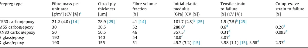
Cured ply properties of the applied UD prepregs (Figures with references are measured values.). Prepreg type Fibre mass per
unit area
Cured ply thickness
Fibre volume fraction
Initial elastic modulus
Tensile strain to failure
Compressive strain to failure [g/m2] (CV [%])a [
lm] [%] [GPa] (CV [%]) [%] (CV [%]) [%] TR30 carbon/epoxy 21.2 (4.0)[14] 28.9[25] 41[14] 101.7 (2.8)b[25] 1.5 (7.5)b[25] –
M55 carbon/epoxy 30 30.5 52 280.0c
0.6d
0.26d
XN80 carbon/epoxy 50 50.5 46 357.5c
0.31d
0.093d
E-glass/epoxy 192 140 54 40.0c
3.07d
– S-glass/epoxy 190 155 51 45.7 (3.2)[15] 3.98 (1.1)[15], 3.56d
2.33d a
Coefficient of variation.
b Measured in specimens with 100/10 mm free length/width. c Calculated for the given fibre volume fraction.
d
[image:3.595.137.454.227.361.2]Based on manufacturer’s data for 60% fibre volume fraction.
Fig. 1.Typical stress-strain response of a UD glass/carbon hybrid specimen with the change in the appearance of the specimen at carbon layer failure.
[image:3.595.309.549.401.597.2]where
e
2bis the expected failure strain of the carbon layer (taken as the manufacturer’s quoted fibre failure strain for design purposes).Table 3shows the specimen configurations designed to demon-strate the potential in the proposed test setup for accurate deter-mination of the failure strain of UD carbon composite layers. The GIICwas taken as 1.1 N/mm, which was measured in similar hybrid specimens with cut central plies[26]. Three of the four hybrid con-figurations had significantly higher energy release rates than the estimated fracture toughness of the glass-carbon interface, there-fore favourable delamination with a stress drop was expected for these. The 2EG/3TR30/2EG configuration had borderlineGIIso tran-sitional behaviour may be expected for that specimen type.
3.3. Finite element modelling of the end-tab region of hybrid specimens
To demonstrate that the stress concentration around the end tab does not affect the strain in the central carbon layer of the designed interlayer hybrid specimens, the longitudinal section of an end-tabbed 2SG/4TR30/2SG type specimen has been modelled
using linear elastic Finite Element (FE) analysis. Quadratic plane stress elements and a fine mesh of about 3050
l
m elements were applied. The material properties of the S-glass/epoxy and TR30 carbon/epoxy layers were selected based on previous studies[16,17]. The 1.5 mm thick end-tab has been made out of cross-ply S-glass laminate, so homogenised material properties of Ex= -Ez= 28.185 MPa, Ey= 10.27 MPa, Gxy= 3.1 GPa and
txy
= 0.27 have been calculated for the layup using the classical laminate theory and applied in the modelling. Note that y is the through-thickness direction in Fig. 3. No cohesive elements or nonlinear material model are applied in this study and perfect bonding between the end tab and the UD S-glass is assumed. In reality how-ever there may be interfacial damage between the end-tab and the specimen, which would reduce the stress concentration. Therefore our linear elastic approach would give a higher stress concentra-tion than that present in a real specimen and so the model and the results are expected to be conservative.The FE model is 80 mm long, consisting of a 40 mm long end tab as well as a 40 mm UD hybrid laminate gauge section with the applied load as shown schematically in Fig. 3. The end tab was 1.5 mm thick and was constrained on the top surface to have zero displacements at all nodes in thexdirection to simulate gripping in a very stiff test fixture. A small compressive vertical deformation of 2
l
m has also been applied to the entire top surface of the tab in the y-direction to keep it straight and simulate the compressive pres-sure of approximately 10 MPa, but the applied value ofy-direction displacement did not affect thex-direction stress distribution around the edge of the end-tab. Anx-direction displacement ofd= 0.8 mm has been applied to the UD hybrid laminate at its end as the main load. Due to symmetry, only a quarter of the specimen was necessary to be modelled and symmetric boundary conditions were applied to the laminate mid-plane and at the centre of the gauge section. [image:4.595.136.473.448.534.2]Fig. 4shows the distribution of x-direction normal strain (e11) around the end tab edge in the FE model. The high strain gradient area is restricted to the surface of the glass layer. Thexdirection
Fig. 4.The distribution of x-direction strain (e11) over the tabbed glass/carbon hybrid specimen. (For interpretation of the references to colour in this figure legend, the reader
is referred to the web version of this article.)
Table 3
Tensile test configurations (Specimen type designation: SG- S-glass, EG- E-glass. Numbers ahead of the material abbreviations indicate the number of plies. Relative carbon layer thickness was normalised by the full specimen thickness).
Lay-up sequence No. of tested spec.
Nominal thickness
Relative carbon layer thickness
GIIat
expected carbon fibre failure strain [–] [mm] [–] [N/mm] 16TR30 non-hybrid
baseline
[image:4.595.139.459.569.728.2]10 0.464[25] 1 – 2EG/4TR30/2EG 6 0.671 0.208 1.536 2EG/3TR30/2EG 5 0.642 0.156 1.055 2SG/4TR30/2SG 5 0.736 0.157 1.430 2SG/4TR30/2SG no end-tab 7 0.736 0.157 1.430 1SG/3TR30/1SG 5 0.397 0.2184 1.225
normal strain variation along three paths (i) on the UD S-glass sur-face (ii) at the TR30 carbon layer mid-plane and (iii) through the thickness at the end tab edge is shown inFig. 5. These paths are highlighted with dashed lines inFig. 4as well. Due to the singular-ity at the edge of the end tab, the normal strain at the UD S-glass top surface has a high gradient (dashed line inFig. 5). This high peak in practice would be relieved by some non-linearity or dam-age in the tab or at the bonded interface between the end-tab and the specimen. However, the strain in the carbon layer varies smoothly from zero at the tabbed area to the maximum applied strain without any singularity or effect of stress concentration. In fact, high values of strain in the glass surface layer around the sin-gularity point actually lead to reduced strain in the carbon layer at the same distance from the tab edge because the resultant force from the integration of the stress distribution have to be constant in the non-tabbed area. In other words, the stress concentration in the glass layers ensures that there is no stress concentration in the carbon layer underneath the tab and stress variation is kept smooth. The variation of strain along the top surface of the carbon layer was found to be very similar to the solid line inFig. 5 and therefore it is not depicted separately. The FE study highlights the benefits of the outer glass layers to shield the stress concentra-tions, therefore gauge section carbon layer failures are expected for the interlayer hybrid tensile specimens, overcoming one of the key limitations of conventional tensile tests.
3.4. Specimen manufacturing
The interlayer hybrid specimens were made by stacking the specified glass and carbon prepreg layers on top of each other,
vac-uum bagging the composite plate and curing it in an autoclave at their common 120°C cure temperature and 0.7 MPa pressure for 2 h. The individual specimens were fabricated with a diamond cut-ting wheel. Finally 40 mm long cross-ply glass/epoxy tabs were bonded to the ends of the specimens except for one set that were tested without end-tabs.
3.5. Test setup and equipment
Testing of the parallel edge specimens was executed under uni-axial tensile loading and displacement control using a crosshead speed of 2 mm/min on a computer controlled Instron 8801 type 100 kN rated universal servo-hydraulic test machine with a regu-larly calibrated 100 kN rated load cell and Instron 2743-401 type hydraulic wedge grips with 50 mm wide Instron 2704-521 type serrated steel jaw faces. The controllable hydraulic grip pressure was set to a moderate 6.9 MPa value, which prevented the slippage of all tested specimen types. Strains were measured using an Ime-trum videogauge system, with a nominal gauge length of 130 mm.
3.6. Tensile test results and discussion
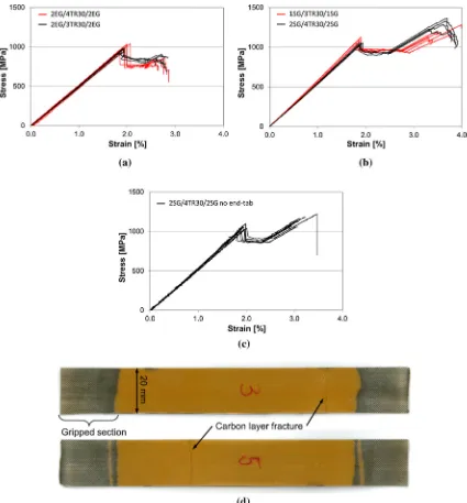
Fig. 6 shows the stress-strain responses of the delaminating hybrid composite specimens. The measured strains at the signifi-cant stress-drops corresponded to the carbon layer failure, which typically took place in the gauge section. The stronger S-glass as the ‘‘embedding” high strain material of the hybrid plates resulted in higher final failure strains (seeFig. 6b) but the detection of the carbon layer failure was possible with both types of glass/epoxy.
The tensile test results of the hybrid specimens are affected by the small thermal residual strains arising from the mismatch in the coefficient of thermal expansion of the carbon and glass fibres. Therefore the residual strains in the different specimen types were calculated. The coefficient of thermal expansion (CTE) of a UD com-posite layer
a
compwas estimated from Eq.(3)which is based on the rule of mixtures, and takes the relative stiffness of the constituents into account as proposed in[27].a
comp¼v
fa
fEf
Ecompþ ð
1
v
fÞa
mEm
Ecomp ð
3Þ
where
v
f,a
fandEfare the volume fraction, the CTE and the elastic modulus of the fibres respectively whilea
mandEmare the CTE and modulus of the matrix material.The residual strains were calculated for force-equilibrium between the carbon/epoxy and glass/epoxy layers assuming con-stant strain through the thickness and a 100°C temperature change from the cure temperature to room temperature. The CTE values for the different fibres included inTable 1were taken from the product datasheets or estimated with general data for the same fibre grade from the literature. (
a
m= 6105[1/K] was assumed for both epoxy matrices in the hybrid composites from the literature.)Table 4shows the results of the tensile tests corrected with the calculated residual strains. It can be seen, that the residual strains are higher for the E-glass configurations, but still minor (less than 3% of the carbon fibre failure strain). The corrected TR30 carbon/ epoxy layer failure strains are consistent, and the overall average value of 1.88% is significantly higher than the 1.50% value obtained from conventional non-hybrid carbon/epoxy specimens and close to the manufacturer’s quoted fibre failure strain.
The significant increase in measured failure strain of the carbon layer in the hybrid specimens compared to that of the non-hybrid ones is primarily attributed to the elimination of stress concentra-tions and the associated premature failure. This is clearly
[image:5.595.40.278.63.395.2]strated by the failure of nearly all of these specimens in the gauge section rather than near the tabs.
Although the volume of carbon/epoxy is relatively small in these specimens, only slightly lower failure strains would be expected if larger specimens were tested due to the size effect
and higher probability of finding a larger defect[28]. The magni-tude of this stressed volume effect is relatively small, for example only 1.7 relative% reduction in strain at failure would be expected for a doubling of specimen volume using a Weibull modulus of 41 (determined for IM7/8552 carbon/epoxy in[8]) so this effect
[image:6.595.91.516.64.521.2]can-Fig. 6.Test results of (a) E-glass/TR30 carbon (b) S-glass/TR30 carbon hybrid configurations, (c) 4S-glass/4TR30 without end-tabs. (d) Photos showing typical tested tab-less specimens. (For interpretation of the references to colour in this figure legend, the reader is referred to the web version of this article.)
Table 4
Tensile test results (Specimen type designation: SG- S-glass, EG- E-glass. Numbers ahead of the material abbreviations indicate the number of plies.). Specimen type designation Compressive thermal residual
strain in carbon layer
Measured carbon layer failure strain
Corrected carbon layer failure strain
[%] [%] (CV[%]) [%]
16TR30 non-hybrid baseline – 1.50 (7.53)[25] –
2EG/4TR30/2EG 0.0404 1.932 (5.87) 1.892
2EG/3TR30/2EG 0.0441 1.927 (1.97) 1.883
2SG/4TR30/2SG 0.0226 1.900 (1.5) 1.877
2SG/4TR30/2SG no end-tab 0.0226 1.917 (3.3) 1.895
[image:6.595.42.562.588.675.2]not explain the observed significant increase in strain here. The proposed test method however would be a good way to study the stressed volume effect further, since it eliminates the stress concentration which tends to mask the size effect in conventional tests.
The ‘‘hybrid effect” whereby failure strains may be higher than in a single material was investigated extensively in [29] by the authors for several configurations of the same S-glass/TR30 carbon material combination with thinner carbon layers. It was shown both experimentally and by modelling that a hybrid effect only arises for thinner carbon layers than the ones used here, therefore this effect is eliminated in the present study.
Fig. 6c and d indicate that it is possible to test the proposed hybrid specimens without end-tabs using standard Instron grips with serrated jaw faces and low hydraulic grip pressure as speci-fied in Section 3.5. Table 4 highlights that very similar failure strains were obtained from tab-less specimens than those from the same configuration with end-tabs. All 7 hybrid specimens without end-tabs consistently showed carbon layer fracture in the gauge section away from the gripped sections, which demon-strates, that the glass plies successfully accommodated the extra tensile stress around the edges of the jaw faces and acted as in-situ end-tabs protecting the carbon/epoxy layer from damage from the grips. Two typical specimens are shown inFig. 6d where the positions of the carbon layer fractures are marked. It was also noted that the glass plies did not encounter visible damage until at least 3% overall strain due to the high failure strain of S-glass fibres.
The differences between the average carbon layer failure strains obtained for the same carbon/epoxy prepreg material from the four different interlayer hybrid configurations are within the scatter bands of the experimental series. The presented test method gave carbon layer failure in the gauge section for the majority of the hybrid specimens and therefore shows excellent potential for accu-rate determination of the failure strain of carbon/epoxy compos-ites. However care has to be exercised in using UD carbon reinforced composite failure strain values obtained from hybrid tensile specimens without any reduction factors in order to be con-servative, as in practice lower strains may be obtained for other reasons, such as the presence of stress concentrations or larger vol-umes of material in the real structure.
4. Proposed test method for compressive failure strain determination
4.1. Concept
Bending of thick beam specimens results in tensile or compres-sive strains in specific layers of the specimens depending on which side of the neutral axis they are positioned. The strains in the spec-imens have a gradient across the thickness, which is assumed to be linear according to the classic beam theory. This is a straightfor-ward way of putting a thin layer of carbon/epoxy in compression as part of a thick glass/carbon interlayer hybrid specimen (see
Fig. 7a). The embedding glass/epoxy layers may also help make
the failure of the carbon plies stable and progressive so that their failure mechanisms can be studied up to higher strains without the risk of premature unstable failure. The strains can be evaluated continuously from optical curvature monitoring of the specimens. Caution however is needed in comparing results to those obtained from conventional compressive tests. For UD composites failing by shear instability it has been shown that the strain gradient can sig-nificantly increase the compressive failure strain [30]. The high strain embedding glass layers may also suppress the shear instabil-ity, which is the primary reason for compressive failure in many
carbon/epoxy composites in conventional direct compression tests. However for materials where failure occurs due to fibre fracture, similar mechanisms may be present in bending and direct com-pression tests, although higher strains may be obtained in bending due to the effect of the smaller stressed volume.
4.2. Specimen design
[image:7.595.307.549.67.290.2]The selected four point bending test setup assures that carbon layer failure takes place between the inner loading noses where the bending moment is maximum and constant. An additional ben-efit of this setup is that the specimen preparation is very simple and cheap with no need for end-tabbing and precision machining (e.g. grinding) typically utilised for direct compression specimens. The double loading noses of the 4 PB fixture reduce the compres-sive stress concentration on the specimen surface compared to the 3 PB test setup and carbon layer failure most likely takes place in the central free section. Similarly to the tension specimens, the thin carbon layer is designed to be covered with one standard thickness glass layer (seeFig. 7a) which protects it against stress concentrations at the loading points, but still allows the damage to be seen. The majority of the specimens were designed to be asymmetric, with the carbon layer positioned close to the com-pression surface of the specimen. Note that the same test could also be used to investigate tensile loading by positioning the spec-imen the other way round in the test fixture, which is an additional benefit. The specimens were also designed to be thick enough to undergo significant surface strains at relatively small deflections in order to minimise the geometric non-linearity of the load-deflection response. This was achieved by adding a number of glass plies to one side of the carbon layer and only one to the other side (seeTable 5for lay-up sequences). High strain S-glass/epoxy plies were used either side of the carbon plies and on the opposite sur-face of the specimen where strains are highest and standard E-glass/epoxy elsewhere. A limiting factor in the specimen design was the possibility of local compressive failure of the surface glass plies under the inner loading noses due to high and concentrated contact forces. The likelihood of this premature failure was
reduced by using reinforced rubber pads under the inner loading noses.Fig. 7a shows the schematic of the specimen geometry and the test setup. The applied setup for the 4 PB tests was the follow-ing: support span: 60 mm, inner span: 20 mm, nominal specimen thickness h= 2.7 mm, specimen width b= 8 mm and specimen lengthl= 80 mm.Table 5shows the specimen configurations and geometry. One set of symmetric specimens comprising two TR30 carbon layers placed symmetrically, close to the top and bottom surfaces were made for strain-gauge validation of the new optical strain evaluation method, while the asymmetric ones containing only one carbon layer on one side of the specimens were made for carbon layer failure strain determination.
4.3. Specimen manufacturing
The glass/carbon hybrid bending specimens were made in a similar way as the tensile ones described in Section3.4. Fabrication of the prismatic specimens was executed simply with a diamond cutting wheel. Strain gauges were bonded on both sides of one symmetric TR30 type specimen and on the carbon side of three of the asymmetric TR30 type specimens for strain measurement validation purposes. One edge of each specimen was hand-polished with medium grit size sandpaper, painted black with per-manent marker and then five white dots were created in the mid-dle section with a white paint marker for optical curvature monitoring.
4.4. Test setup and equipment
Four point bending of the prismatic specimens was executed at a constant 3 mm/min crosshead speed on a computer controlled Instron 8872 type 25 kN rated universal servo-hydraulic test machine with a regularly calibrated 10 kN rated load cell. The posi-tions of the five dots on the edge of the specimens between the inner loading noses were recorded with an Imetrum optical strain measurement system (seeFig. 7b).
4.5. New optical strain evaluation method for four point bending
Since the aim of the study is to determine the failure strain of the carbon layer, it is essential to measure the strains in the carbon layer during the test accurately, which may be done with conven-tional strain gauges or optically, with the assumption of a linear strain distribution through the thickness for both approaches. Optical methods have the advantages of being contactless, cheap and less demanding in terms of specimen preparation time than conventional strain gauges. The curvature of the bending speci-mens can be determined from a curve fitted through dots at recorded positions on the edge of the specimen. Although four point bending (4 PB) is more difficult to set up than three point bending, it was selected because it has constant bending moment between the inner loading noses, which results in a constant radius deformed shape keeping the curve fitting simple. Since there is negligible shear, the assumption of linear strain variation through the thickness is valid. If the positions of the dots are recorded at a
high sampling rate during the test, it is possible to get similarly processable strain data to that given by strain gauges.
The sequence of the data acquisition and evaluation during and after the 4 PB tests was the following:
1. Recording thexandypositions of the centre of the five dots on the edge of the specimen (seeFig. 7b) in pixels with a 17 Hz sampling rate during the test with an Imetrum optical strain measurement system.
2. Transformation of the coordinates of the dots from pixels to millimetres using the videos recorded by the Imetrum system. (The thickness of the specimens measured previously with a calliper can be determined in pixels on specific frames of the video in the initial and in a slightly deformed state to calibrate the position data.)
3. Fitting circular arcs to each set of five dot displacements using the Curve Fitting toolbox in Matlab.
4. Calculation of the curvature (
j
= 1/R) of the specimens from the radius of the fitted curves.5. Calculation of the strain (
e
= z⁄j
) in the specimens at specific through thickness coordinates corresponding to the carbon layer top and bottom positions from the neutral axis (seeFig. 7a).
The required position of the neutral axis is calculated with the classical laminate and beam theories from the tensile stiffness and compliance matrices ([A] and [a] = [A]1) and the through thickness positions of the layers of the asymmetric hybrid speci-mens. The strain evaluation relies on accurate determination of the neutral axis position, which will be affected by the non-linearity in the carbon fibre stress-strain response. To check the sensitivity of the method to the stiffness of the carbon, the neutral axis position was reanalysed by arbitrarily cutting the modulus of the TR30 carbon/epoxy in half, and checking the change in the cal-culated failure strain. The change in the neutral axis position was 2.05%, and the change in evaluated failure strain was only 2.69 rel-ative% even with the large 50% modulus reduction of the carbon layer. This quick check indicated that the strain evaluation method is not highly sensitive to the neutral axis position, because the con-tribution of the carbon plies to the bending stiffness of the whole specimen is only moderate.
Fig. 7a shows the schematic of the four point bending test setup, and an asymmetric specimen with a carbon/epoxy layer on the compressive side. Fig. 7b shows an annotated video frame taken with the Imetrum optical strain measurement system, suitable for tracking and recording the positions of the five dots painted on the edge of the specimen. The fitted circular arc and the con-stant radius are also indicated inFig. 7b which illustrates a sym-metric TR30 type specimen with strain gauges bonded on both sides for the validation of the new strain measurement method.
4.6. Optical strain measurement validation
[image:8.595.44.565.86.148.2]The new optical strain measurement approach was validated against conventional strain gauge measurements executed on the same specimens. Both top and bottom faces of one symmetric
Table 5
Four point bending specimen types (Designation: SG- S-glass, EG- E-glass).
Specimen type designation Lay-up sequence No. of tested specimens Nominal thickness Width Support span Inner span [mm] [mm] [mm] [GPa] Symmetric TR30 [SG1/TR302/SG3/EG5]S 1 2.8 8 60 20
Asymmetric TR30 [SG1/EG14/SG2/TR302/SG1] 6 2.70
Asymmetric M55 [SG2/EG13/SG2/M552/SG1] 5 2.71
TR30 and the carbon side of three asymmetric TR30 type speci-mens were equipped with strain gauges as well as dots for optical strain measurement. One symmetric TR30 type specimen was deformed up to 2% surface strain in multiple runs and three asym-metric TR30 type specimens were loaded until carbon layer failure.
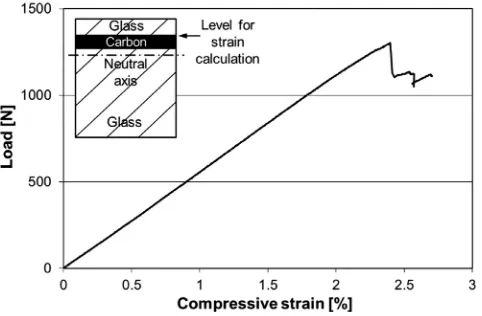
Fig. 8shows one typical load-strain graph of both configurations, comparing the absolute values of the surface strains measured by the two different techniques. Excellent agreement can be judged visually from the graphs ofFig. 8. Strain values determined with the two different approaches were compared at increasing load levels. In the case of the symmetric specimen type, the difference between the gauge strain readings and the optical strain was com-parable to the difference between the two strain gauge readings (less than 1 relative% on average for two separate loading cycles and max. 2.5 relative%). In the case of the asymmetric specimens with strain gauges only on the carbon side, the differences between
the measured gauge and optical strains were found to be very small, with a maximum of around 1%. According to the results of the optical strain validation tests, it was concluded, that the new optical strain measurement method is capable of determining the surface strains of 4 PB specimens with similar accuracy to that of conventional strain gauges, with the benefit that the maximum strain to be measured was not limited by gauge fracture, de-bonding or specimen surface damage. This advantageous feature is demonstrated onFig. 8b, although the optical strains were only approximate after the first fracture of the specimen (i.e. significant load drop), because the neutral axis may have been displaced by asymmetric damage or failure of specific layers in the specimen.
4.7. Compression test results and discussion
Figs. 9, 11 and 13show typical load-compressive strain curves obtained for different grade carbon/epoxy plies. The strains were evaluated from the curvature data assuming a linear through thick-ness distribution and plotted for the top of the carbon layer where the strain was the highest within the layer, because failure would be expected to initiate there. The variation of the strain across the carbon layer is small (around 3.5 relative% for the asymmetric TR30 specimens), because of the low layer thickness.
[image:9.595.85.499.67.223.2]Fig. 9shows a typical load-compressive strain curve of an asym-metric M55 type specimen. The change in slope (see Table 6) indicates the progressive fibre fracture in the carbon layer of the hybrid specimen which is a surprising phenomenon, not normally observed in compression tests. The fitted line shown on the graph was used to determine the carbon layer failure strain, where the curve deviated from the straight line. The measured average com-pressive failure strain of the M55 carbon/epoxy was 0.456%, signif-icantly higher than the 0.26% calculated from the compressive strength and modulus quoted on the fibre datasheet as UD composite properties. The measured compressive strain increased further to 0.51% after thermal strain correction (seeTable 6). Spec-imens loaded up to a point beyond the carbon layer failure and unloaded before final failure, showed a periodic striped pattern
[image:9.595.40.279.268.423.2]Fig. 8.Typical load-absolute strain graphs of (a) symmetric TR30 and (b) asymmetric TR30 specimens measured with strain gauges and optically. (For interpretation of the references to colour in this figure legend, the reader is referred to the web version of this article.)
[image:9.595.35.553.690.753.2]Fig. 9.Typical load-strain graph of asymmetric M55 type specimens based on optically measured strains at the top of the carbon layer (Line fitted to the initial part of the curve is included to show the progressive carbon layer failure detection from the change in slope). (For interpretation of the references to colour in this figure legend, the reader is referred to the web version of this article.)
Table 6
Summary of four point bending test results.
Specimen type Thickness Change in slope at carbon layer failure
Measured compressive failure strain
Compressive thermal residual strain in carbon layer
as shown inFig. 10a. The visual assessment indicated that the M55 carbon layer progressively fragmented under compressive loading and interfacial damage at the top glass-carbon layer interface became visible.Fig. 10b shows a micrograph of the edge of a spec-imen loaded up to 700 N and unloaded. The sharp cracks through the carbon layer marked with white arrows confirm that the car-bon plies were fragmented under compression and no kink bands were observed.
Fig. 11a shows a typical overall load-strain graph of an asym-metric XN80 type specimen. The graph does not show any notice-able feature until the first load-drop at around 2.5% strain except for a slight non-linearity in the initial section.Fig. 11b magnifies this initial section and reveals that the UHM carbon layer started failing progressively at around 0.1% strain as indicated by the sig-nificant (up to 30%, seeTable 6) reduction in the slope of the curve. This figure highlights the good quality of the generated strain data even in the low strain regime.
The determination of the carbon layer failure strain was performed with the help of a fitted line as done earlier for the asymmetric M55 type specimens. The parameters and the consis-tency of the decrease in slope were analysed for all six XN80 test graphs by fitting straight lines to the initial and the second quasi-linear part of the graphs and the early non-linearity proved to be present consistently in all the test graphs. The results are summarised inTable 6. For the XN80 carbon/epoxy, the strain at the limit of linearity corrected with the thermal residual strain (0.141%) is significantly higher than the compressive failure strain quoted by the fibre manufacturer for the UD epoxy matrix compos-ite (0.093%). The determined carbon failure strain and the decrease in slope showed acceptable coefficients of variation. The reason for the early reduction in slope of the stress-strain curve is that the carbon layer is significantly damaged early on during compression loading, but the glass plies continue carrying the load until final failure which is the fracture of the surface glass ply on the com-pression side of the specimen.
The tests of two specimens were interrupted after the initial non-linearity and examined under an optical microscope (see
Fig. 12). A periodic damage pattern was observed on the top
glass-carbon layer interface which was caused by progressive
frag-Fig. 10.Damage analysis of an asymmetric M55 type specimen after an interrupted four point bending test (a) Photograph showing the striped pattern of the carbon/glass layer interface in top view (b) Micrograph of the longitudinal edge confirming the fragmentation of the carbon plies (Arrows point on through thickness cracks in the carbon layer).
[image:10.595.316.556.350.701.2]mentation of the XN80 carbon/epoxy layer under compression. No kink-bands were visible in the micrographs taken from the edge of the specimen (seeFig. 12b) and dense fragmentation of the carbon plies was observed.
The high strength asymmetric TR30/epoxy specimens failed catastrophically, with a load drop as shown inFig. 13, and the glass ply on the surface was fractured and delaminated together with the carbon one. This is completely different from the progressive failure type observed in the case of the high modulus carbon spec-imens. No signs of kink-bands were found during microscopy of the tested specimens although the catastrophic failure may have affected the appearance of the fracture surface. The determination of the failure mechanism of these specimens requires further work. The carbon layer failure strains at the first load drop were easily detectable. The slight non-linearity of the curve before the load drop was the result of the increasing geometrical non-linearity of the test setup at large deflections. The measured average compres-sive failure strain is 2.46%, much higher than expected for high strength carbon composites. This is partly due to the test method successfully reducing the stress concentrations but may also be because the hybrid configuration suppresses the shear instability failure mechanism. The measured compressive failure strain of the carbon plies is also significantly higher than the tensile failure strain of the same material (1.88%) obtained with the proposed hybrid specimens and the tensile failure strain of TR30 fibres (1.9%) quoted by the manufacturer.
The data presented inTable 6demonstrates that the proposed 4 PB tests of interlayer hybrid specimens and the novel strain eval-uation procedure are able to produce good compressive failure strain data for carbon/epoxy composites with acceptable scatter. A key benefit of the proposed test method is that it provides an opportunity to load carbon/epoxy plies until high strains without premature catastrophic failure and allows for study of the failure mechanisms. The two high modulus type carbon samples (XN80 and M55) failed by progressive ply fragmentation with no kink bands observed. This failure mechanism has not been reported in
[image:11.595.143.449.65.335.2]the literature in compression for UD carbon reinforced composites according to the best knowledge of the authors. On the contrary, the high strength TR30 carbon plies failed catastrophically, at high strains suggesting that the failure may have been delayed by the supporting glass plies. The lack of stiffness loss, post mortem microscopy and the unstable final failure at high strains all indicate that the high strength TR30 carbon fibre reinforced plies did not fragment. However a deeper understanding of the mechanism behind the observed catastrophic failure requires further work. The obtained failure strain values for all the tested carbon/epoxy composites were higher than the fibre manufacturer’s data. The increase in strain can be attributed to (i) elimination of the stress concentrations by the use of 4 PB specimens and (ii) the small stressed volume and associated reduced defect probability. For the high strength TR30 fibres the increase in strain was also due to the suppression of the shear instability by the strain gradient and support of the glass plies. For the high- and ultra-high modulus
Fig. 12.Damage analysis of an asymmetric XN80 type specimen after an interrupted four point bending test (a) Micrograph showing the striped pattern of the carbon/glass layer interface in top view (b) Micrograph of the longitudinal edge confirming the fragmentation of the carbon plies (Arrows point on cracks in the carbon layer).
[image:11.595.308.549.387.545.2]carbon composite specimens (with M55 and XN80 fibres) failing by progressive fibre fracture (i.e. fragmentation), another reason why the strain was higher was because the change in slope corresponds to the point where multiple fractures of the ply occur as it frag-ments, rather than a single first catastrophic fracture. For these reasons the measured compressive strains cannot be taken as material design allowable strains to failure, as this could be signif-icantly un-conservative.
5. Conclusions
The following conclusions were drawn from the presented study of new failure strain determination approaches for UD car-bon/epoxy composites:
A new UD glass/carbon interlayer hybrid specimen type was successfully applied for determination of the carbon/epoxy layer tensile failure strain. The measured strains were signifi-cantly higher than those measured in conventional non-hybrid carbon/epoxy baseline specimens. This is primarily due to the elimination of stress concentrations since the specimens were designed to exclude the hybrid effect and the volume effect on the failure strain is small.
The FE study indicated that the inner carbon layer in the hybrid tensile specimens did not experience any stress concentration around the end-tabs. This prediction was confirmed as the posi-tions of the carbon layer failures in the experiments were far away from the grips in the majority of the specimens. A further advantage of the proposed hybrid tensile specimens is
that end-tabs can be eliminated altogether, as the surface glass layers protect the carbon plies and act as in-situ end-tabs. The compressive failure strains of three different (high
modulus, ultra-high modulus and high strength) UD carbon fibre/epoxy layers were successfully determined with the novel interlayer hybrid four point bending specimens applying the developed optical strain evaluation method.
Progressive ply fragmentation was consistently observed during the four point bending based compression tests of the high (M55) and ultra-high modulus (XN80) carbon/epoxy plies. The absence of kink-bands suggests that the resulting failure strains are close to the intrinsic compressive failure strain of the carbon fibres. The unique fragmentation failure mechanism is different from that previously reported in compression of high strength carbon/epoxy.
The failure of the high strength carbon plies (TR30) was catas-trophic, and the obtained compressive failure strains were sig-nificantly higher than those from conventional compression tests, due to the suppression of stress concentrations at the load introduction points and delayed final failure due to the strain gradient and support from the surrounding glass layers. No kink-bands were observed, but more work is needed to fully understand the compressive failure mechanisms of the high strength carbon/epoxy plies under four point bending. Caution is required in interpreting the high compressive strains
due to the strain gradient and small stressed volume, which means that they cannot be used as design allowables.
Acknowledgement
This work was funded under the UK Engineering and Physical Sciences Research Council Programme Grant EP/I02946X/1 on High Performance Ductile Composite Technology in collaboration with Imperial College London. Gergely Czél acknowledges the Hungar-ian Academy of Sciences for funding through the Post-Doctoral Researcher Programme fellowship scheme, the János Bolyai
schol-arship and the Hungarian National Research, Development and Innovation Office - NKFIH for funding through grant ref. OTKA K 116070. The authors acknowledge Putu Suwarta for his help with a micrograph. The authors acknowledge Hexcel Corporation and North TPT for supplying materials for this research. All data required for reproducibility are provided within the paper.
References
[1] ISO 527-5. Plastics – Determination of tensile properties – Part 5: test conditions for unidirectional fibre-reinforced plastic composites; 2009. [2] ASTM D5083-10 Standard Test Method for Tensile Properties of Reinforced
Thermosetting Plastics Using Straight-Sided Specimens.
[3] ASTM D3039/D3039M–08 Standard Test Method for Tensile Properties of Polymer Matrix Composite Materials.
[4]Hodgkinson JM. Mechanical testing of advanced fibre composites. Woodhead Publishing; 2000.
[5]Adams DO, Adams DF. Tabbing guide for composite test specimens Technical report. Washington, DC: Office of Aviation Research; 2002.
[6]De Baere I, Van Paepegem W, Degrieck J. On the design of end tabs for Quasi-static and fatigue testing of fibre-reinforced composites. Polym Compos 2009;30:381–90.
[7]Wisnom MR, Atkinson JW. Reduction in tensile and flexural strength of unidirectional glass fibre-epoxy with increasing specimen size. Compos Struct 1997;38:405–11.
[8]Wisnom MR, Khan B, Hallett SR. Size effects in unnotched tensile strength of unidirectional and quasi-isotropic carbon/epoxy composites. Compos Struct 2008;84:21–8.
[9] Wisnom MR, Maheri MR. Tensile strength of unidirectional carbon fibre-epoxy from tapered specimens. In: 2nd European Conf. on Composites Testing and Standardisation. Hamburg; September 1994. p. 239–47.
[10] Short D, Summerscales J. Hybrids – a review Part 1. Techniques design and construction. Composites 1979;10:215–21.
[11]Short D, Summerscales J. Hybrids – a review Part 2. Physical properties. Composites 1980;11:33–8.
[12]Kretsis G. A review of the tensile, compressive, flexural and shear properties of hybrid fibre-reinforced plastics. Composites 1987;18:13–23.
[13]Swolfs Y, Gorbatikh L, Verpoest I. Fibre hybridisation in polymer composites: a review. Compos A Appl Sci Manuf 2014;67:181–200.
[14]Czél G, Wisnom MR. Demonstration of pseudo-ductility in high performance glass-epoxy composites by hybridisation with thin-ply carbon prepreg. Composites Part A 2013;52:23–30.
[15]Czél G, Jalalvand M, Wisnom MR. Demonstration of pseudo-ductility in unidirectional hybrid composites made of discontinuous carbon/epoxy and continuous glass/epoxy plies. Composites Part A 2015;72:75–84.
[16]Jalalvand M, Czél G, Wisnom MR. Numerical modelling of the damage modes in UD thin carbon/glass hybrid laminates. Compos Sci Technol 2014;94:39–47. [17]Jalalvand M, Czél G, Wisnom MR. Damage analysis of pseudo-ductile thin-ply UD hybrid composites – a new analytical method. Composites Part A 2015;69:83–93.
[18]Jalalvand M, Czél G, Wisnom MR. Parametric study of failure mechanisms and optimal configurations of pseudo-ductile thin-ply UD hybrid composites. Composites Part A 2015;74:123–31.
[19] ASTM D3410/D3410M-03. Standard test method for compressive properties of polymer matrix composite materials with unsupported gage section by shear loading; 2008.
[20] ASTM D695-10 Standard Test Method for Compressive Properties of Rigid Plastics.
[21]Haberle JG, Matthews FL. An improved technique for compression testing of unidirectional fibre-reinforced plastics; development and results. Composites 1994;25:358–71.
[22]Adams DF, Welsh JS. The wyoming combined loading compression (CLC) test method. J Compos Technol Res 1997;19:123–33.
[23] ASTM D6641/D6641M-14. Standard Test Method for Compressive Properties of Polymer Matrix Composite Materials Using a Combined Loading Compression (CLC) Test Fixture.
[24] ASTM D5467/D5467M-97. Standard Test Method for Compressive Properties of Unidirectional Polymer Matrix Composite Materials Using a Sandwich Beam. [25] Fuller JD. Pseudo-ductility of thin ply angle-ply laminates. PhD thesis,
University of Bristol; 2015.
[26] Czél G, Jalalvand M, Wisnom MR. Development of pseudo-ductile hybrid composites with discontinuous carbon- and continuous glass prepregs. In: Proceedings of ECCM-16 conference. Seville, June 2014.
[27]Schapery RA. Thermal expansion coefficients of composite materials based on energy principles. J Compos Mater 1968;2:380–404.
[28]Wisnom MR. Size effects in the testing of fibre-composite materials. Compos Sci Technol 1999;59:1937–57.
[29]Wisnom MR, Czel G, Swolfs Y, Jalalvand M, Verpoest I. Larissa G. Hybrid effects in thin ply carbon/glass unidirectional laminates: accurate experimental determination and prediction. Composites Part A 2016;88:131–9.