City, University of London Institutional Repository
Citation
:
Alwis, L., Bremer, K., Sun, T. and Grattan, K. T. V. (2013). Analysis of the
Characteristics of PVA-Coated LPG-Based Sensors to Coating Thickness and Changes in
the External Refractive Index. IEEE Sensors Journal, 13(3), pp. 1117-1124. doi:
10.1109/JSEN.2012.2230534
This is the accepted version of the paper.
This version of the publication may differ from the final published
version.
Permanent repository link:
http://openaccess.city.ac.uk/7844/
Link to published version
:
http://dx.doi.org/10.1109/JSEN.2012.2230534
Copyright and reuse:
City Research Online aims to make research
outputs of City, University of London available to a wider audience.
Copyright and Moral Rights remain with the author(s) and/or copyright
holders. URLs from City Research Online may be freely distributed and
linked to.
City Research Online:
http://openaccess.city.ac.uk/
[email protected]
Analysis of the Characteristics of PVA-Coated
LPG-Based Sensors to Coating Thickness and
Changes in the External Refractive Index
Lourdes Alwis, Kort Bremer, Tong Sun, and Kenneth T. V. Grattan
Abstract— Recent research has shown that the transmission spectrum of a long period grating (LPG) written into an optical fiber is sensitive to the thickness and the refractive index (RI) of a thin layer deposited on it, a concept which forms the basis of a number of optical fiber sensors. The research reported herein is focused, in particular, on sensors of this type to create a design with an optimized thickness of the deposited layers of polyvinyl alcohol (PVA) on LPGs forming the basis of a highly sensitive probe. In creating such sensors, the dip-coating technique is used to minimize deleterious effects in the attenuation bands resulting from the inhomogeneity of the coated surface. In this paper, LPGs with different coating thicknesses are uniformly coated with thin layers of PVA and submerged in oils of known RI over the range from 1.30 to 1.70, to create effective RI probes. It is observed that when the coating thickness reaches a particular value that enables a substantial redistribution of the optical power within the overlay, a maximum sensitivity of the sensor can be achieved, even when the overlay has a RI higher than that of the cladding. The experimental results obtained through the characterization of the devices developed are shown to be in good agreement with the results of a theoretical model.
Index Terms— Long period grating (LPG), overlay thickness, polyvinyl alcohol (PVA), refractive index (RI).
I. INTRODUCTION
A. Long Period Gratings for Sensing Applications
Long Period Gratings (LPGs) have a period typically in the range 100 μm to 1 mm, and their structure promotes cou-pling between the propagating core mode and co-propagating cladding modes [1]. This coupling between the core and the cladding modes results in the transmission spectrum of the fibre which comprises a series of attenuation bands centred at discrete wavelengths, where each attenuation band corresponds to the coupling of the fundamental core mode to a different cladding mode. The centre wavelengths of the attenuation bands are sensitive to the period of the LPG and to the differ-ence between the effective RI of the core and each cladding mode. Thus, LPGs are sensitive to the local environment such
Manuscript received March 23, 2012; accepted November 21, 2012. Date of publication November 29, 2012; date of current version February 4, 2013. The associate editor coordinating the review of this paper and approving it for publication was Prof. Venkat R. Bhethanabotla.
The authors are with the School of Engineering and Mathematical Sci-ences and the City Graduate School, City University, London EC1V 0HB, U.K. (e-mail: [email protected]; [email protected]; t.sun@ city.ac.uk; [email protected]).
Color versions of one or more of the figures in this paper are available online at http://ieeexplore.ieee.org.
Digital Object Identifier 10.1109/JSEN.2012.2230534
as temperature, strain, bend radius and to the RI of the medium surrounding the fibre [2], with these effects forming the basis of a number of significant optical fibre-based sensors, as they are important alternatives to the more widely used Fibre Bragg Grating (FBG) devices. The advantages of the use of LPGs over FBGs in a variety of sensor systems have been discussed elsewhere [3] and are not reproduced in detail here.
In this work the LPGs used as the basis of the probe were fabricated by irradiating a particular length of a photosensitive fibre with light from an ultraviolet (UV) laser through a selected amplitude mask with a known period of typically several hundred microns. When the LPG in the fibre was illuminated using a broadband light source, the LPG enabled the coupling of light from the propagating core mode to the co-propagating cladding modes at discrete known wave-lengths, therefore producing several attenuation bands in the transmission spectrum [4]. The mode coupling occurs between the fundamental LP01core mode and the co-propagating LP0m
cladding modes (m = 1, 2, 3...) when the phase matching
condition given below is satisfied [5]
βcore−βcladm =
2π
(1)
whereβcore−βcladm is the difference between the propagating
constants of the fundamental core and the mthcladding modes andis the grating period. The propagation constants for the
fundamental core mode and the mth cladding mode can be
expressed as [1]
βcore =
2π
λ n
e f f
core βcladm =
2π
λ n
e f f
clad,m. (2)
By combining the above equations, the resonance wave-length,λres, for the loss band can be obtained as
λres=(ne f fcore−ne f fclad,m) (3)
where ne f fcore and ne f fclad,m are the effective refractive indices
of the fundamental core mode and the mth cladding mode
respectively andis the grating period of the LPG. This loss band can be used to characterize the optical fibre sensor based on the LPG.
1420 1430 1440 1450 1460 1470 1480 1490 1500
1.25 1.3 1.35 1.4 1.45 1.5 1.55 1.6 1.65 1.7 1.75
Refractive Index (a.u.)
W
a
v
e
le
n
g
th
(n
m
[image:3.595.51.290.86.224.2])
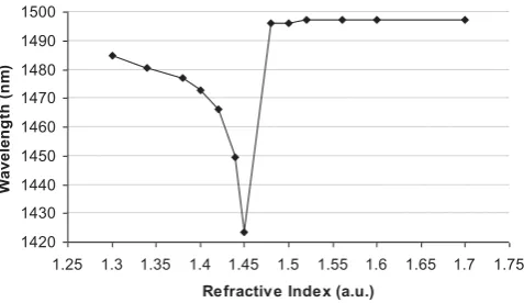
Fig. 1. Plot of the wavelength shift when a bare LPG with a period of 250μm is exposed to various RI oil.
RI of a medium surrounding the cladding on a LPG can thus be expressed as [6]
dλ dnsur =
dλ
dne f fclad,m
dne f fclad,m dnsur
(4)
whereλis the wavelength of the attenuation band and nsur is the RI of the surrounding material.
Fig. 1 shows the result of an experimental characterization of a typical LPG itself, showing the effect of the external RI variation on the LPG resonance wavelength, when a bare LPG is exposed to different oils with known refractive indices. It can be seen that the external RI value changes over the range from 1.30 to 1.45, where the resonance wavelength of the bare LPG shifts towards the shorter wavelengths, with a highest sensitivity being observed when it is approaching 1.45 (equal to the value of the cladding RI). This is because under this specific circumstance, the fibre core is effectively surrounded by an “infinite” cladding, which does not support any discrete mode and this leads to the disappearance of the resonance bands as there are no cladding modes which can be coupled to the core mode [7].
When the surrounding RI value is greater than that of the cladding, the resonance bands reappear at wavelengths slightly shifted towards longer wavelengths than those seen when the bare LPG was surrounded by air. The increase in the value of the external RI can, as a result, no longer change the wavelengths (as shown in Fig. 1 when the RI varies from 1.48 and 1.7) but the intensity of the resonance bands. This is because when the surrounding RI value is higher than that of the cladding, the LPG does not support any of the cladding modes and the core mode couples with the radiation modes and the confined radiated field by the fibre forms leaky modes [8]. Therefore the intensity of the resonance bands of the coated LPG forming the sensor increases as the leaky modes are better confined with the increase of RI but making no change in the resonant wavelength. It should be noted that these results are obtained when the cladding is considered to have been surrounded by a medium of infinite thickness.
The sensitivity of the bare LPG to the external RI variation, as shown in Fig. 1, forms the basis of a suite of sensors using LPGs, for example as a RI sensor [9], a chemical concentration
sensor [10], a biochemical sensor [11], [12], a liquid level sensor and for tuneable spectral filters for various industrial production quality control [13]–[15]. These applications, how-ever, are mostly limited by the requirement that the external RI needs to be smaller than that of the cladding. To address this issue, further research has been undertaken to explore the possibility of improving the sensitivity of the LPG to external RI values greater than that of the cladding by using coating materials that have a higher RI than that of the cladding [16]–[20]. Rees et al [16] showed for the first time that the central wavelengths of the LPG attenuation bands exhibit a dependence on the thickness and the RI of an overlay material (with the RI higher than that of the cladding) by detecting the resonance wavelength shift due to an incremental increase in the thickness of a thin-film overlay of tricosenoic acid surrounding a LPG.
When the fibre grating is coated with a material that has a RI higher than that of the cladding, the cladding modes are confined within the fibre structure, including the cladding and the coating. Therefore there is a small portion of the optical power radiated inside the overlay and the amount of optical power within the overlay is determined by both the RI and the thickness of the overlay. This causes the attenuation bands of a particular grating to shift after it has been coated with a material and the amount of shift in the attenuation band of a particular cladding mode is determined both by the RI and the thickness of the coating material. As the thickness of the overlay (that has a RI higher than that of the cladding) is increased, the overlay acquires the ability to guide one of the cladding modes and thus the coating acts as a waveguide. When the coating thickness approaches the condition where it can guide a mode within the overlay, the optical power in the overlay reaches its maximum value and so does the evanescent wave, interacting with the surrounding environment. Due to the maximized evanescent wave at this thickness, a higher sensitivity to external RI variation is achieved compared to other overlay thicknesses. At this particular thickness, the original cladding mode is now guided inside the overlay and its original “position” is thus replaced by the cladding mode next to it causing a re-distribution of the optical power within the overlay that leads to a reorganization of the rest of the cladding modes.
Fig. 2. Spectrum of a coated LPG as a function of the overlay thickness (simulation) [22]. Refractive index of the overlay is 1.52 and the surrounding medium is water (RI=1.33).
coated LPG with a period of 320μm as a function of coating thickness, over the range from being uncoated to having a thickness of 5000 nm, under the condition that the RI of the overlay is 1.52 and that the overlay is surrounded by water. The mode re-organization that occurs is clearly visible at coating thicknesses near to 500 nm and 2250 nm in particular. It can be seen that at a coating thickness of around 500 nm where one of the mode transitions occurs, the attenuation bands that correspond to the HE1,12 mode shift to a value near to the attenuation band of the HE1,10mode and the attenuation band of the HE1,10 mode shifts to that of the HE1,8mode etc.
B. Coating Techniques
There are a number of publications in the literature that verify the enhancement of the characteristics of a bare LPG by the deposition of an overlay that has a RI greater than that of the cladding. However, nearly all of them use either Electrostatic Self-Assembly (ESA) monolayer process or the Langmuir–Blodgett (LB) technique for the coating deposition. The main reason for this is the ability in both these techniques to control the thickness of the overlay at a molecular level. However, none of the sensors prepared, either by the ESA monolayer process or by the LB nano-deposition techniques, is able to demonstrate the attenuation bands predicted by the theoretical model, reported by Del Villar et al [22] as shown in Fig. 2, when the overlay-thickness is within the transition region [16], [23]. This has been explained by Del Villar et al through the inclusion of an imaginary component in the RI of the overlay [17]. In a recent publication by Cusano et al [20], dip-coating has been used to deposit thin layers of polymer on a LPG and the experimental results shows that the attenuation bands did not suffer from the vanishing effect within the transition region, making it possible to detect the wavelength shift during the transition region.
Dip coating is a simple and an effective method to be implemented for coating or depositing polymers in aqueous form. The dip coating process also reduces the amount of
coating solution required and the thickness of the coated layer deposited on the sample can be easily manipulated by adjusting the withdrawal speed. However, a disadvantage of dip-coating seen by some groups can be the difficulty in achieving an exact and specified thickness, therefore there have been limited reports showing the use of the dip-coating technique to verify the theoretical predictions. ESA and LB techniques, however, are more widely reported. In this work, the utilization of the dip-coating technique has enabled the observation of the attenuation bands, enabling the attenuation band at the highest sensitivity region to be used and to experimentally verify the results of the theoretical simulation presented by Del Villar et al [22].
This work explores experimentally the overlay thickness effect on the LPG-based sensor performance when Poly-Vinyl Alcohol (PVA) is used as a coating material, based on a comparison with the predictions of the theoretical model reported by Del Villar et al and also to draw a comparison with published work using other techniques. It was reported in a previous paper by some of the authors [24] on a PVA coated LPG device that a sensor coated with a thin overlay performed in a different manner to that with a thick layer–providing better humidity sensitivity for the smaller layer thickness. This work is designed to explore further the underpinning sensing mechanism that relate to the coating thickness and the RI of the coating material, with an aim to explore the use of attenuation bands predicted by the theoretical model but “missing” in the experimental analysis when the results of using ESA or LB coating techniques were reported.
II. EXPERIMENTALPROCEDURE
A. Fabrication of the Sensor
The LPGs used in this work that formed the basis of the probes were fabricated using a metal amplitude mask with
a period of 250 μm, illuminated by light from a 248 nm
KrF excimer laser with a pulse energy of 8 mJ and a pulse frequency of 100 Hz. The period of 250 μm was chosen as it is close to the grating period reported in the theoretical model [22]. Following the fabrication, the LPGs were annealed at 100 ºC for 15 hrs before being ready for use in the subsequent experiments.
PVA is a water soluble polymer which has excellent adhe-sion properties and was chosen in particular in this work as the RI of PVA (1.53 for the pure dried product at 589.3 nm [25], [26]) is higher than that of the fibre cladding and its RI value (1.53) is very close to the figure of 1.52 simulated in Fig. 2 in the theoretical model published by Villar et al. The PVA used was supplied by Kuraray Specialties Europe (KSE) in granular form and has a degree of hydrolysis of 98-99%. The PVA granules (dry) were mixed with de-ionized water to form a 15% (wt/wt) PVA solution, which was placed in an oven at 90 ºC for∼ 3 hrs to allow the PVA granules to fully dissolve. Thus the PVA/water solutions were prepared for coating the LPGs as thin films through a slow evaporation process of a solvent.
optical fibre
PVA coating
[image:5.595.47.293.88.195.2](a) (b)
Fig. 3. SEM images of the uniformly PVA-coated LPG of the coating thickness of 1μm. (a) Longitudinal view (arrows indicate the diameter of the fiber with the coating). (b) Magnified cross-sectional view (arrows indicate the PVA layer on the fiber).
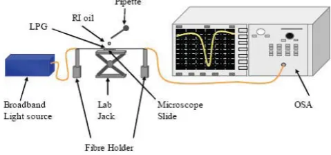
Fig. 4. Experimental setup to study the RI effects on the coated LPG transmission spectrum by varying the surrounding RI value using various oils of different RI values.
The samples were first dipped into the solution and then drawn from the solution at a speed of 217 μm/sec (optimized from a series of tests undertaken to achieve a smooth and uniform coating) and this process was repeated when a thicker coating was required. To achieve consistency in this process, an auto-mated dip coating device (Holmarc Slides and Controls Ltd.) was used. Subsequently these coated LPGs were placed in an oven to be dried at 80 ºC for one hour. The RI of the PVA liquid solution (15% wt/wt) was measured to be near to that of water and also confirmed to be around 1.35 from the manufacturer’s data sheet. During the curing of the coated LPG at high temperature, the water content of the PVA film was expected to evaporate and therefore the film RI would be near to that of its dried RI value of 1.53.
B. LPG Coating Evaluation
It was important to confirm that, after curing, a uniform layer of PVA had been deposited on the surface of a LPG and Fig. 3 shows typical images captured using a Scanning Elec-tron Microscope (SEM) after the coating process is completed. These images show the characterization and the high level of uniformity of the coatings on the fibres using the dip-coating technique.
After the coating process was completed, one end of the coated LPG that formed the key element of the probe was connected to a broadband light source, Halogen Source (Ocean Optics LS-1), and the other to an Optical Spectrum Analyzer (OSA), as shown schematically in Fig. 4. The spectrometer offers a wavelength measurement range from 600 nm to
1700 nm and a spectral resolution of 0.6 nm. To evaluate the performance of the sensor to different values of RI, each coated LPG sample was carefully placed between two fibre holders which were mounted on an optical bench as illustrated in Fig. 4. A microscopic slide was placed on a lab jack with its height being adjustable and the coated LPG was placed carefully on the top to enable the oils with known refractive indices (supplied by Cargille Laboratories) to be applied on the surface. Since PVA is oil resistant [27], penetration of oil into the PVA layer is considered to be negligible. After each test, the LPG and the microscopic slide were cleaned carefully before being exposed to the next oil sample. To ensure that no residue of the oil used remained, prior to the next oil sample being used, the output was monitored using the OSA until the spectrum of the coated LPG returned to its original state (when it was exposed to air). Throughout the experiment, the temperature and relative humidity were
maintained constant and recorded to be 25 ± 1 ºC and
33% ± 2% respectively. Under these conditions, prior work has shown that the impact on the resonance wavelength of the PVA coated LPG due to variations in temperature or relative humidity is insignificant [7].
III. RESULTS ANDDISCUSSION
A. Effect of the PVA Coatings
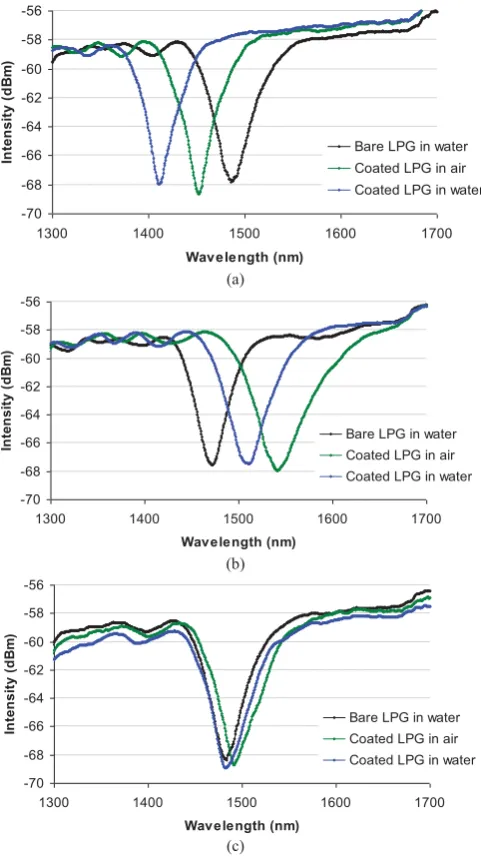
Fig. 5 summarizes the results obtained before and after the LPG probes were coated with PVA layers of different thicknesses. Fig 5(a) shows that the attenuation band of the coated LPG (in air) has experienced a blue shift of∼35 nm after coating compared to that of the bare LPG in water, for a coating thickness of 500 nm. The attenuation band is further
shifted by ∼40 nm when the coated LPG is submerged in
water and the shift between thecoated and the uncoated LPG in water is∼75 nm (blue shift). Fig. 5(b) shows the spectra obtained from a LPG before coating (in water) and after coating of 1 μm of PVA (in air) and finally when the coated LPG is submerged in water. The attenuation band experiences a red shift of∼70 nm upon coating (in air) compared to that
of the bare LPG in water and then blue shift by ∼30 nm
when submerged in water. The shift of the attenuation band between thecoated and the uncoated LPG in water is∼40 nm (red shift).
It can be observed in Fig. 5(c) that there is only a small red shift of around ∼10 nm resulting from the coating of PVA (in air), compared to that of the bare LPG in water. When the coated LPG probe is submerged in water the attenuation band of the spectra then shifts to the blue by ∼8 nm. The shift between thecoated and the uncoated LPG in water is∼2 nm (red shift).
[image:5.595.48.288.254.366.2]-70 -68 -66 -64 -62 -60 -58 -56
1300 1400 1500 1600 1700
Wavelength (nm)
In
te
n
s
it
y
(
d
B
m
)
Bare LPG in water Coated LPG in air Coated LPG in water
(a)
-70 -68 -66 -64 -62 -60 -58 -56
1300 1400 1500 1600 1700
Wavelength (nm)
In
te
n
s
it
y
(
d
B
m
)
Bare LPG in water Coated LPG in air Coated LPG in water
(b)
-70 -68 -66 -64 -62 -60 -58 -56
1300 1400 1500 1600 1700
Wavelength (nm)
In
te
n
s
it
y
(
d
B
m
)
Bare LPG in water Coated LPG in air Coated LPG in water
[image:6.595.303.546.84.261.2](c)
Fig. 5. Transmission spectra of LPG samples before and after being coated with PVA with thicknesses of (a) 500 nm, (b) 1μm, and (c) 2μm.
when the sensor was submerged in water. As can be seen from Fig. 5(a), a resonance wavelength shift of 75 nm was obtained for the 500 nm PVA coating between the uncoated and coated LPG attenuation bands when both were submerged in water. It is apparent from Fig. 6 that the 500 nm thickness lies within a transition region, as explained in the introduction, and would therefore result in a relatively larger wavelength shift compared to the other two coating thicknesses. Consequently, for the same reason, the 500 nm PVA coated LPG would be expected to have a higher sensitivity in sensor use.
When the coating thickness is increased to 1μm, a red shift of∼40 nm is observed. Similarly, when the coating thickness was increased to 2μm, a negligible or small red shift of only
∼2 nm is seen. Both these coating thicknesses (i.e. 1μm and 2 μm) do not lie within the transition region and therefore would not produce as significant a wavelength shift as that of the 500 nm.
Bare 320 μm LPG in water
~500 nm~ 1 μm ~ 2 μm ~ 75nm
~ 40nm ~ 2nm
Fig. 6. Illustration of the wavelength shifts with different coating thickness when the LPG period is 320μm [22].
In this work, the 8th cladding mode of a 250 μm LPG
whose attenuation band falls at a wavelength around 1500 nm has been chosen for the sensing purposes. The external RI sensitivity of the sensor depends on both the grating period and the particular cladding mode involved. Given the close proximity of the two periods from the experimental work presented in this paper and the published simulated results (i.e. for 250 and 320 microns respectively) and the selection of the most sensitive resonance wavelength of the 8thcladding mode for the 250μm grating, the impact arising from the small difference of 70 μm in the LPG periods is not significant. Therefore the experimental data obtained (at 250 μm) are not expected to be very different from the theoretical data predicted for the period of 320 μm grating [28]. The study carried out confirms this - the experimental results obtained from the 250μm LPG-based sensor has shown to be in good agreement with the simulation for a 320μm LPG reported by Villar et al [22].
B. Optimization of the RI Sensor Probe Using Coated LPGs
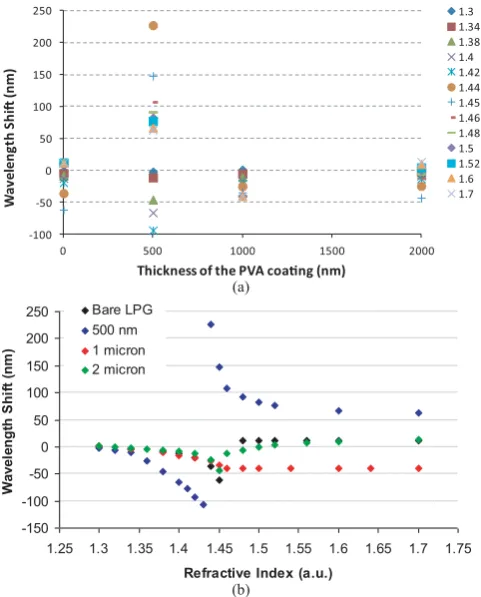
Building on the above experimental results, the coated LPGs were subsequently evaluated in terms of their RI response by being exposed to a series of different oils of known RI, using the setup shown in Fig. 4. The transmission spectra of these coated LPGs when they were thus subjected to these known RI variations over the range from 1.30–1.70 were monitored using the OSA and the results obtained are shown in Fig. 7(a) and 7(b), together with that of a bare LPG (0 coating thickness) for comparison. Fig. 7(a) shows clearly the greater spread seen at a thickness of 500 nm and the sensitivity arising from this is shown in Fig. 7(b) in comparison to the other thicknesses.
[image:6.595.50.291.86.515.2]-100 -50 0 50 100 150 200 250
0 500 1000 1500 2000
W
av
elen
gt
h S
hi (n
m)
Thickness of the PVA coang (nm)
1.3 1.34 1.38 1.4 1.42 1.44 1.45 1.46 1.48 1.5 1.52 1.6 1.7
(a)
-150 -100 -50 0 50 100 150 200 250
1.25 1.3 1.35 1.4 1.45 1.5 1.55 1.6 1.65 1.7 1.75
Refractive Index (a.u.)
Wavel
en
g
th
S
h
if
t (
n
m
)
Bare LPG 500 nm 1 micron 2 micron
[image:7.595.49.290.86.385.2](b)
Fig. 7. Comparison of the sensitivity of the 240-μm LPG coated with different thicknesses of PVA to the external RI variation (a) thickness effect and (b) external RI effect.
performance). When the overlay thickness is ∼2 μm, its performance is similar to that of the ∼1 μm coated LPG over the external RI change from 1.30 to 1.45. However, when the external RI is larger than that of the cladding, there is a continuous red shift of the attenuation band wavelength with the increase of the external RI, showing a higher sensitivity to the external RI variation as a RI sensor compared to that of the bare and the 1 μm thickness coated LPGs.
When the overlay thickness was∼500 nm and the external RI varies from 1.30 to 1.70, two distinct regions, sepa-rated by a value closer to the cladding RI, are observed. Compared to the performance of all the other LPGs, the 500 nm PVA coated LPG has demonstrated a much higher sensitivity throughout most of the RI range used. It shows
∼100 nm of blue shift when the external RI changes from
1.30 to 1.44. A significant blue shift (of ∼160 nm) was
observed when the external RI varies from 1.44 to 1.60, although when the external RI is higher than 1.60, there is no significant wavelength change. The average sensitivity over the RI range between 1.44 and 1.48 was calculated to be ∼3 μm/RIU which is the highest sensitivity reported in the literature for a single layer coating within this particular region [4], [29], [30]. The reason for the higher sensitivity of the 500 nm PVA coating is because its thickness has been created to lie within the transition region. The other two coating thicknesses, i.e. 1 μm and 2 μm examined in some
detail do not lie within this region and therefore would not involve as significant a wavelengthshift with the variations in the external RI.
Thus for sensor applications where a high sensitivity and wide operation range are preferable, the work shows that a thin layer of polymer with a RI higher than that of the cladding and a coating thickness that is set to lie within the high sensitivity region (depending upon the particular RI of the coating material) proves to be most suitable. It should also be noted that the required thickness for optimum performance depends both on the refractive index as well as on achieving a uniform coating, such as has been demonstrated with the use of the dip coating approach used in this work.
IV. CONCLUSION
In this research, a series of tests has been undertaken to achieve a better understanding of the impact of the overlay thickness and its uniformity on the performance of a LPG for its ultimate use as a high sensitivity, reproducible RI sensor. The experimental data obtained have confirmed the theoretical prediction that the relationship between the wavelength shift and the sensitivity of the device is related to the refractive index as well as the deposition of a uniform coating of the overlay.
Building on the theoretical and experimental evaluations of the LPGs at the core of the device (with and without an overlay), the coated sensors were submerged in oils of known refractive indices from 1.30 to 1.70 to characterize their behav-iour to variations in the external environment. It was observed that when the coating thickness was ∼500 nm, the highest sensitivity has been demonstrated, compared to the other two coating thicknesses considered, showing promise for use as a RI sensor and offering a high sensitivity. Operational ranges of more than 100 nm and more than 160 nm were achieved for the RI variations over the range between 1.30 to 1.44 and 1.44 to 1.70 respectively–these being amongst the highest sensitivities achieved for polymer-coated LPGs for external RI sensing reported in the literature. This highest sensitivity has been demonstrated through a coating thickness that lies within the transition region of a LPG coated with a material that has a refractive index of ∼1.53. The dip-coating technique has demonstrated its value to control effectively the coating thickness and the coating quality to enable the observation of some specific attenuation bands predicted by theory but not achieved by either using ESA or LB techniques.
It can be concluded that the sensitivity of a bare LPG to variations in the external RI can be greatly enhanced by depositing a polymer that has a RI greater than that of the cladding and by careful control of the thickness of the layer. Research is still on-going to refine the above sensor design to ensure its optimization for a range of practical applications for RI sensitivity.
ACKNOWLEDGMENT
Women Graduates (FfWG) and the support of the Worshipful Company of Tin Plate Workers, alias Wire Workers for one of us (Lourdes Alwis) is also gratefully acknowledged.
REFERENCES
[1] R. Kashyap,Fibre Bragg Gratings. New York: Academic, 1999. [2] V. Bhatia, “Applications of long-period gratings to single and
multipa-rameter sensing,”Opt. Exp., vol. 4, no. 11, pp. 457–466, 1999. [3] V. Bhatia, “Properties and sensing applications of long-period gratings,”
Ph.D. dissertation, Virginia Polytechn. Inst. State Univ., Blacksburg, VA, 1996.
[4] I. M. Ishaq, A. Quintela, S. W. James, G. J. Ashwell, J. M. Lopez-Higuera, and R. P. Tatama, “Modification of the refractive index response of long period gratings using thin film overlays,”Sens. Actuators B, vol. 107, no. 2, pp. 738–741, 2005.
[5] A. M. Vengsarkar, P. J. Lemairc, J. B. Judkins, V. Bhatia, T. Erdogan, and J. E. Sipe, “Long-period fiber gratings as band-rejection filters,”J. Lightw. Technol., vol. 14, no. 1, pp. 58–65, 1996.
[6] Y. Zhu, J. H. Chong, M. K. Rao, H. Haryono, A. Yohana, P. Shum, and C. Lu, “A long-period grating refractometer: Measurements of refractive index sensitivity,” inProc. SBMO/IEEE MTT-S IMOC Conf., Sep. 2003, pp. 901–904.
[7] T. Venugopalan, T. L. Yeo, T. Sun, and K. T. V. Grattan, “LPG-based PVA coated sensor for relative humidity measurement,” IEEE Sens., vol. 8, no. 7, pp. 1093–1098, Jul. 2008.
[8] Y. Koyamada, “Numerical analysis of core-mode to radiation-mode coupling in long-period fiber gratings,” IEEE Photon. Technol. Lett., vol. 13, no. 4, pp. 308–310, Feb. 2001.
[9] H. J. Patrick, A. D. Kersey, and F. Bucholtz, “Analysis of the response of long period fiber gratings to external index of refraction,”J. Lightw. Technol., vol. 16, no. 9, pp. 1606–1612, 1998.
[10] R. Falciai and A. G. Mignani, “A long period gratings as solution concentration sensors,” Sens. Actuators B, vol. 74, no. 1, pp. 74–77, 2001.
[11] F. Baldini, M. Brenci, F. Chiavaioli, A. Giannetti, and C. Trono, “Optical fibre gratings as tools for chemical and biochemical sensing,” Anal. Bioanal. Chem., vol. 402, no. 1, pp. 109–116, 2012.
[12] V. Mishra, N. Singh, U. Tiwari, and P. Kapur, “Fiber grating sensors in medicine: Current and emerging applications,” Sens. Actuators A, vol. 167, no. 2, pp. 279–290, 2011.
[13] T. Allsop, L. Zhang, and I. Bennion, “Detection of organic aromatic compounds by a long period fibre grating optical sensor with optimised sensitivity,”Opt. Commun., vol. 191, no. 6, pp. 181–190, 2001. [14] S. W. James and R. P. Tatam, “Optical fibre long-period grating sensors:
Characteristics and application,”Meas. Sci. Technol., vol. 14, pp. 49–61, Nov. 2003.
[15] T. M. Libish, M. C. Bobby, J. Linesh, P. Biswas, S. Bandyopadhyay, K. Dasgupt, and P. Radhakrishnan, “Fiber optic sensor for the adulter-ation detection of edible oils,”J. Optoelectron. Adv. Mater., vol. 5, no. 1, pp. 68–72, 2011.
[16] N. D. Rees, S. W. James, R. P. Tatam, and G. J. Ashwell, “Optical fiber long-period gratings with Langmuir-Blodgett thin-film overlays,”Opt. Lett., vol. 27, no. 9, pp. 686–688, 2002.
[17] I. D. Villar, M. Achaerandio, I. R. Matias, and F. J. Arregui, “Deposition of overlays by electrostatic self-assembly in long-period fiber gratings,”
Opt. Lett., vol. 30, no. 7, pp. 720–722, 2005.
[18] I. D. Villar, I. R. Matias, and F. J. Arregui, “Long-period fiber gratings with overlay of variable refractive index,”IEEE Photonics Technol. Lett., vol. 17, no. 9, pp. 1893–1895, May 2005.
[19] O. Duhem, J. F. Henninot, M. Warenghem, and M. Douay, “Demonstra-tion of long-period-grating efficient couplings with an external medium of a refractive index higher than that of silica,” Appl. Opt., vol. 37, no. 31, pp. 7223–7228, 1998.
[20] A. Cusano, A. Iadicicco, P. Pilla, L. Contessa, L. Campopiano, A. Cutolo, and M. Giordano, “Mode transition in high refractive index coated long period gratings,”Opt. Exp., vol. 14, no. 1, pp. 19–34, 2005. [21] I. D. Villar, I. R. Matias, and F. Arregui, “Optimization of sensitivity in long period fiber gratings with overlay deposition,”Opt. Exp., vol. 13, no. 1, pp. 56–69, 2005.
[22] I. D. Villar, J. M. Corres, M. Achaerandio, F. J. Arregui, and I. R. Matias, “Spectral evolution with incremental nanocoating of long period fiber gratings,”Opt. Lett., vol. 14, no. 25, pp. 11972–11981, 2006. [23] I. D. Villar, I. R. Matias, F. Arregui, and M. Achaerandio,
“Nanode-position of materials with complex refractive index in long-period fiber gratings,”J. Lightw. Technol., vol. 23, no. 12, pp. 4192–4199, 2005.
[24] T. Venugopalan, T. Sun, and K. T. V. Grattan, “Long period grating-based humidity sensor for potential structural health monitoring,”Sens. Actuators A, vol. 148, no. 2, pp. 57–62, 2008.
[25] A. Gaston, F. Perez, and J. Sevilla, “Optical fiber relative-humidity sensor with polyvinyl alcohol film,” Appl. Opt., vol. 43, no. 21, pp. 4127–4132, 2004.
[26] D. S. Ballantine and H. Wohltjen, “Optical waveguide humidity detec-tor,”Anal. Chem., vol. 58, no. 5, pp. 2883–2885, 1986.
[27] K. Akiyama and Y. Asai, “Oil-resistant sheet material,” U.S. Patent 7 588 831, Jan. 3, 2009.
[28] X. Shu, L. Zhang, and I. Bennion, “Sensitivity characteristics of long-period fiber gratings,”J. Lightw. Technol., vol. 20, pp. 255–266, Jan. 2002.
[29] S. Korposh, S. W. James, S. W. Lee, S. Topliss, S. C. Cheung, W. J. Batty, and R. P. Tatam, “Fiber optic long period grating sensors with a nanoassembled mesoporous film of SiO2 nanoparticles,” Opt.
Exp., vol. 18, no. 2, pp. 13227–13238, 2010.
[30] Z. Wang, J. R. Heflin, R. H. Stolen, and S. Ramachandran, “Analysis of optical response of long period fiber gratings to nm-thick thin-film coatings,”Opt. Exp., vol. 13, no. 1, pp. 2808–2813, 2005.
Lourdes Alwiswas born in Negombo, Sri Lanka, in 1983. She received the B.Eng. degree from the Department of Electrical Engineering, City University London, London, U.K., in 2005, where she is currently pursuing the Ph.D. degree in fiber optic sensors.
Kort Bremer received the Diploma degree in electrical engineering from Hochschule Wismar, Wismar, Germany, the Ph.D. degree in optical fiber sensors from the University of Limerick, Clare, Ireland.
He was a Post Doctoral Research Fellow with City University London, London, U.K. His current research interests include optical fiber sensors and photonic devices.
Tong Sun was born in Jiang Su Province, China, in 1968. She received the Bachelors of Engineer-ing, the Masters of EngineerEngineer-ing, and the Doctor of Engineering degrees in mechanical engineering from the Department of Precision Instrumentation, Harbin Institute of Technology, Harbin, China, in 1990, 1993, and 1996, respectively, and the Doctor of Philosophy degree in applied physics from City University London, London, U.K., in 1999.
She was with City University London as an Aca-demic Visitor and later a Research Fellow in fiber optic temperature measurement using luminescent techniques. She was an Assistant Professor with Nanyang Technological University, Singapore, from 2000 to 2001, and is currently a Senior Lecturer with City University London, since rejoining in April 2001. Her current research interests include optical fiber sensors, optical communications and laser engineering.
Kenneth T. V. Grattan was born in County Armagh, Northern Ireland, in 1953. He received the Bachelors and Ph.D. degrees in physics from The Queen’s University, Belfast, U.K., in 1974 and 1978, respectively.
![Fig. 2.Spectrum of a coated LPG as a function of the overlay thickness(simulation) [22]](https://thumb-us.123doks.com/thumbv2/123dok_us/1531803.105777/4.595.50.290.85.264/fig-spectrum-coated-lpg-function-overlay-thickness-simulation.webp)