Mode-Matching Analysis of a Shielded
Rectangular Dielectric-Rod Waveguide
Colin G. Wells
, Student Member, IEEE,
and James A. R. Ball
, Member, IEEE
Abstract—Rectangular cross-sectional dielectric waveguides are widely used at millimeter wavelengths. In addition, shielded dielec-tric resonators having a square cross section are often used as filter elements; however, there is almost no information available on the effect of the shield. Rectangular or square dielectric waveguide is notoriously difficult to analyze because of the singular behavior of the fields at the corners. Most published analyses are for materials with a low dielectric constant, and do not include the effects of a shield. This paper describes a numerically efficient mode-matching method for the analysis of shielded dielectric-rod waveguide, which is applicable to both low and high dielectric-constant materials. The effect of the shield on the propagation behavior is studied. The shield dimensions may be selected such that the shield has a neg-ligible effect so that results can be compared with free-space data. The results are verified by comparison with several sets of pub-lished data, and have been confirmed by measurement for a nom-inal of 37.4.
Index Terms—Dielectric resonators, dielectric waveguides, electromagnetic propagation in nonhomogeneous media, mode-matching methods, shielding.
I. INTRODUCTION
D
IELECTRIC waveguides are an attractive alternative to metal waveguides at millimeter-wave frequencies due to their lower propagation loss, lower cost, and easier fabrication [1]. Rectangular dielectric waveguides form a large proportion of these and have uses in integrated optics and millimeter-wave integrated circuits and transmission lines. However, there has always been difficulty obtaining accurate propagation coeffi-cients for the various modes on these structures. There is no closed-form solution to the problem [1] and the methods used either rely on approximations, as in the procedure originated by Marcatili [2] and improved by Knox and Toulios [3], or are nu-merical in nature. The main nunu-merical techniques range from the circular harmonic analysis of Goell [4], finite-element [5] and finite-difference [6] procedures, to mode matching.Mode-matching methods have been applied to the dielectric image line by Solbach and Wolff [7], and to the homogeneous inverted strip guide by Mittraet al.[8]. The latter used a sim-ilar procedure to [7], with the momatching techniques de-veloped by Mittra and Lee [9]. In a very comprehensive paper, Strube and Arndt [10] have applied the method of Solbach and Wolff to the shielded dielectric image line. The first part of their paper used this procedure, together with the inclusion of an extra
Manuscript received February 8, 2005; revised April 13, 2005. The work of C. G. Wells was supported by the University of Southern Queensland under a scholarship.
The authors are with the Department of Engineering, University of Southern Queensland, Toowoomba, Qld., Australia.
[image:1.594.304.551.165.258.2]Digital Object Identifier 10.1109/TMTT.2005.855148
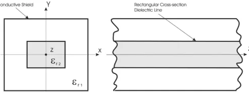
Fig. 1. Rectangular dielectric line and shield.
electric wall, to analyze propagation on infinite shielded image guide. As well as propagating and evanescent modes, complex modes and backward waves were identified and thoroughly in-vestigated. Complex modes can only exist in pairs having com-plex conjugate propagation coefficients, and couple so that the total power flow is always reactive. A backward wave is one in which the power flows in the opposite direction to the wave-fronts. The second part of their paper finds the scattering matrix of a transition from shielded dielectric image guide to rectan-gular waveguide, by matching the tangential fields at the inter-face. A comparison of measured and calculated results were used to verify the method. The results obtained by Strube and Arndt correspond to those modes that can exist in the ditric-rod waveguide shown in Fig. 1 when the -axis is an elec-tric wall. However, these do not include some of the dominant modes, for which the -axis is a magnetic wall. To obtain the full set of modes for this waveguide, it is necessary to consider all four types of symmetry.
An analysis of complex and backward waves in an inhomo-geneously filled waveguide has been carried out by Omar and Schunemann [11]. A method to predict the presence of complex modes in inhomogeneous lossless dielectric waveguide can be found in [12].
An alternative mode-matching (boundary element) method for the shielded dielectric-rod waveguide, incorporating dyadic Green’s functions, was developed by Collin [13] and Collin and Ksienski [14].
A problem with numerical solutions is that they can suffer from slow convergence due to divergence of the electric field at the corners of the dielectric where the refractive index changes abruptly [15]. However, for most purposes, sufficient accuracy can still be obtained for a relatively small number of basis functions.
In a typical situation, the permittivity of the dielectric will be higher than the surrounding medium (usually air) so that the electromagnetic fields will be concentrated in the dielectric line, and the proportion outside it will decay away exponentially.
Fig. 2. One-quarter of the rectangular dielectric line with a shield, showing mode-matching regions.
The ability of a high-permittivity material to contain and con-centrate the fields, together with the availability of high- tem-perature stable materials, has led to the development of the di-electric resonator as a filter element. In filter applications, the dielectric resonators are often enclosed in metallic shields or cavities to prevent unwanted coupling, as shown in Fig. 1.
Cavity filters incorporating dielectric resonators are widely used in mobile base stations and other demanding applications. Traditionally, many of these have used cylindrical resonators. Designers have sought to reduce the size of these filters by using multiple mode cavities. This has led to increased interest in res-onators that have a square cross section, and also in cubical resonators. Dielectric filter cavities may be analyzed using the methods developed by Zaki and Atia. The propagation char-acteristics of an infinite cylindrical waveguide containing a di-electric rod were first established. A cylindrical cavity was then modeled as a length of this guiding structure, terminated in short lengths of empty waveguide [16]. In a later paper, this was ex-tended to cylindrical dielectric resonators in rectangular wave-guide and cavities [17]. This paper represents the first step in a similar study of the shielded square section dielectric resonator.
II. ANALYSISUSING THEMODE-MATCHINGMETHOD
An advantage of a mode-matching method is that it has rela-tively good processing speed due to its semianalytical nature. It also allows visualization of the fields in the structure by solving for the unknown coefficients of the basis function equations. Another advantage is that it can be used with reasonably high values of permittivity ([10] show results as high as ). The other numerical methods cited, with the exception of the finite-difference method of Schwieg and Bridges [6], have only been applied to relatively low values .
Due to the symmetrical nature of the shielded dielectric wave-guide, only one-quarter of the structure needs to be analyzed. Fig. 2 shows how the cross section is divided into three regions. Regions and surround the dielectric rod and are filled with a medium of permittivity , which, in this paper, will be con-sidered to be air . Region is the dielectric rod with
permittivity . The outer shield will be considered as a perfect electric conductor (electric wall). The bottom and left-hand-side (LHS) symmetry planes, coincident with the - and -axes, may be either electric or magnetic walls. The selection of wall types will determine the types of symmetry that can exist in the struc-ture.
In this paper, as in [8] and [10], a modification of the mode-matching method of Solbach and Wolff [7] will be used so that the effect of the proximity of the shield to the dielectric can be ascertained. However, to provide calculation of all modes possible in this structure, additional basis functions to cater for the full range of symmetries (see Section II-A) have had to be provided. This variation will be called the modified Solbach and Wolff (MSW) method through the remainder of this paper.
A. Basis Functions
The modes that can propagate in a shielded rectangular di-electric-rod waveguide are all hybrid modes, i.e., they always have field variation along either the horizontal or vertical di-electric-rod boundaries and, thus, have both electric- and mag-netic-field components in the longitudinal direction [18]. In each of the regions in Fig. 2, the field patterns for these modes can be built up from superpositions of appropriate basis functions, which are transverse magnetic or transverse electric with respect to the -direction. These will be designated (electric) and (magnetic), respectively, and are indicated by subscripts and . The cross section has two axes of symmetry, which means there are four possible symmetries. In this paper, these will be classified according to the behavior of the -field component, following Schweig and Bridges [6]. For example, superscript will indicate that is an even function of and an odd func-tion of .
It is most efficient to derive the basis function fields from vector potentials. From Balanis [19], the magnetic vector po-tential for a wave propagating in the -direction in a non-magnetic region with rectangular boundaries is of the form
(1)
The longitudinal-field components can then be obtained from
(2)
(3)
From these expressions, it can be seen that and will have opposite types of symmetry. The longitudinal electric field will be as follows:
(4)
each symmetry. For the case of , an even function of and odd function of ( ), these are as follows:
(5)
where
where
(6)
and is the mode number in region II.
From (2) and (5), the resultant magnetic vector potential equations for the shielded dielectric waveguide are then
(7)
From (7), the other components of the basis functions for each region can be derived using the partial differential equa-tions from Balanis [19].
Similarly, the electric vector potential equations for a mode propagating in the -direction are found to be
(8)
The other components of the basis functions can again be found using the partial differential equations from Balanis [19].
Continuity of the transverse fields at the boundary , between regions and must also be taken into account so that wavenumbers and can be found. At this boundary, wavenumbers to allow for continuity of phase. Then, for even , odd symmetry, and
modes,
(9)
and from this
(10)
and also
(11)
Substituting (10) into (11) gives the transcendental equation
(12)
The wavenumbers can then be obtained from numerical solu-tions of (12) after substitution of the relation
(13)
which is derived using and the region II equa-tions of (6).
Similarly, for the modes,
(14)
and the transcendental equation for the wavenumbers becomes
(15)
The equations for the other symmetries of the and basis functions can be similarly derived.
B. Mode Matching at the Boundary Between Regions
The parallel fields and must be continuous at the mode-matching boundary between regions I and II ( , ). In the case of the electric field, this leads to the equations
(16)
For continuity of the magnetic fields,
where is the right-hand side (RHS) of (10) and (14) for the and modes, respectively, and is used to reduce the number of unknown coefficients. The above pair constitute a doubly infinite set of linear equations for the modal coefficients and . To simplify these equations, and to expand their number to equal the number of unknowns, the electric and mag-netic fields in region I were used as testing functions. Only the -dependent factors are required, and these have been desig-nated and , respectively. The following orthogo-nality relations are required:
for (18)
where and are the indices used to find wavenumbers or [as in (6)] for each mode number in region I. That is, (16) and (17) are multiplied by or testing functions or from region I, respectively, and integrated over the interval at , as per Mittra et al. [8]. The infinite set of equations so formed is reduced by truncating the number of basis functions used to a value that can be practically computed and will give a desired accuracy in the solution. The maximum values of the mode indices and are and , respectively. An equal number of basis functions were used in both regions I and II to alleviate any problems with relative convergence [20], [21]. In matrix form, the equations using the electric field and odd symmetry are
.. .
.. .
.. .
.. .
(19)
The sub-matrices of the LHS of (19) are diagonal matrices, the elements of which are the result of (18). The zero sub-matrices are the result of the component being zero for . The elements of the sub-matrices of the RHS of (19) are coupling integrals of the form
For this odd case, the subscripts and are odd integers only and are equivalent in number to the number of basis func-tions used . For the even case, there will be a total of even integers (including zero).
In abbreviated form, the matrix equations can be written as
(20)
The magnetic field equations are similar, and in abbreviated form are
(21)
C. Propagation Coefficient and Unknown Mode Coefficients of the Structure
A homogeneous system of equations may be formed from (20) and (21) as follows:
(22)
The eigenvalues of (22) are the propagation coefficients of the modes of the structure. These modes can be propagating, evanescent, complex, or backward wave types and are found by substituting a range of propagation coefficient values into the equations and finding those values for which the determinant is zero.
To determine that the propagation coefficients found are physically sensible, and also to find the type of mode each rep-resents, it is essential to calculate the unknown coefficients and plot the field patterns. A selected coefficient is chosen as unity or some appropriate factor. In this paper, the coefficient chosen is that of the first TM mode in region II and, thus, the associated matrix element values are (electric) to (magnetic), as shown. Consequently, the coefficients are reduced by one to and the and matrices are reduced by a column to and . Hence, (22) can be written as
electric
.. .
magnetic
.. .
(23)
The system of (23) has more equations than unknowns (i.e., overdetermined), but can still be solved for the normalized values of the unknown coefficients by the use of the MATLAB
operator “ .” This function gives a least squares solution for these truncated equations and, thus, produces a best fit result [22].
sufficient decimal places to accurately cover the range of the size of numbers in the equation matrix. However, the number of modes required for sufficient accuracy is well below this limit.
Once the coefficients are found, they can then be substituted into the field equations so that the field components can be de-termined from the sum of the basis functions at a number of spatial grid points, and the resultant field in the structure can be plotted as a superposition of all the components.
III. DISCUSSION ANDCOMPARISON OFRESULTS
WITHOTHERMETHODS
To confirm the validity of this method, the propagation coefficients were calculated for a number of frequency ranges and permittivity values, and compared to the results from other methods. All of the calculations and measurements reported here are for a square cross section, i.e., a square dielectric rod symmetrically located within a square shield. The structure will be characterized by the aspect ratio for the dielectric rod and for the shield. In the following, the normalization applied by Schwieg and Bridges [6] will be used, where and are the normalized frequency and propagation coefficient, respectively:
(24)
The method described in this paper gives the propagation co-efficients of the possible modes for each symmetry used. The designations of the modes on the dielectric line in this paper is the same as that used by Marcatili, Goell, and others. Modes will be identified as or , where or denotes the di-rection of polarization of the main electric field, and and are the number of maxima in the - and -directions over the
-plane of the dielectric.
A. Comparison of Method Convergence Properties
A comparison of the convergence properties of Goell’s method and the MSW versus the number of basis functions used is shown in Fig. 3. The dielectric rod was square
with and, in free space, with a normalized fre-quency of . The square shield dimension ratio in the MSW method had , which is of sufficient distance from the dielectric (see Fig. 4) so as to be a good approximation of free space. As can be seen, only approximately 7 and 7 basis functions are required for good convergence. At 11 and 11 basis functions, the MSW method and Goell’s results are within 1%.
B. Effect on the Propagation Coefficient of the Proximity of the Shield to the Dielectric Rod
[image:5.594.306.550.63.254.2]The effect of the proximity of the shield on the propaga-tion coefficients of the first few modes to propagate ( and ) is shown in Fig. 4. It can be seen that, for a shield to dielectric dimension ratio value , the shield has only a small effect on the propagation coefficient. These results
[image:5.594.303.551.305.496.2]Fig. 3. Comparison of the convergence properties of the Goell [4] and MSW methods when used with a square cross-sectional dielectric-rod waveguide (" = 37:4)in free space whereBis the normalized propagation coefficient.
Fig. 4. Effect of the proximity of the shield on ," = 37:4,a = b = 6mm, frequency= 3:5GHz.
are verified by considering the situation where the shield size approaches that of the dielectric . In both cases, the propagation coefficients found using the MSW method ap-proached those calculated for dielectric-filled rectangular wave-guide, as shown in this figure.
C. Comparison of Methods Used for Calculation of the Rod Propagation Coefficient in Free Space
Fig. 5. Comparison of the calculation methods of MSW and Goell [4] for a square cross-sectional dielectric-rod waveguide in free space whereBandV are the normalized propagation coefficient and frequency, respectively(" = 13:1).
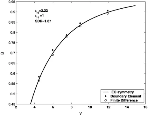
Fig. 6. Comparison of the calculation methods of MSW, the boundary-element method of Collin [13], and the finite-difference method of Schweig and Bridges for a shielded square cross-sectional dielectric-rod waveguideSDR = 1:87and" = 2:22, whereBandV are the normalized propagation coefficient and frequency, respectively.
D. Comparison of Methods for Calculation of the Shielded Dielectric-Rod Propagation Coefficient
The MSW method with symmetry shows good agreement with propagation coefficients obtained by Collin [13] and Collin and Ksienski [14] using a boundary-element method and the finite-difference method of Schweig and Bridges. These results
are shown in Fig. 6. The mode is , , ,
and .
E. Propagation Coefficient Verses Frequency Mode Diagram of the Shielded Dielectric-Rod Waveguide
[image:6.594.305.551.65.255.2]The propagation coefficient verses frequency-mode diagram, of the first few modes to propagate, is shown in Fig. 7. The 12-mm square dielectric has a permittivity , the
Fig. 7. Mode diagram for the first few modes to propagate in a shielded dielectric-rod waveguide plus some of the associated complex modes, evanescent modes, and backward waves. SR = 1(a = 6 mm), SDR = 2(a = 12mm), and" = 37:13. The modes are labeled with their associated symmetry in parentheses.
shield is 24-mm square . This figure shows differ-ences from that of the dielectric image line reported by Strube and Arndt [10]. The MSW method (for a shielded dielectric-rod
waveguide with and ) reveals a coupled
mode, which is dominant in this structure, and also the mode is associated with a degenerate . The and modes and their associated higher order modes do not occur in the dielectric image line and the studies of this structure in [7] and [10] use only a combination of and symmetry. Some of the complex, evanescent, and backward wave modes for the shielded dielectric rod, mentioned in Section II-C, are also shown in Fig. 7. The symmetry associated with each mode is shown in parentheses.
F. Field Patterns of the First Few Modes to Propagate on the Shielded Dielectric-Rod Waveguide
The transverse electric and magnetic fields of the mode, in one-quarter of the structure, and determined from sym-metry, are shown in Fig. 8. The calculated propagation
coeffi-cient is at 3.5 GHz. The modes have
symmetry. In a square cross section, using the same parameters, these are degenerate, as they have the same propagation coef-ficient . The resultant field plot is a superposition of both modes, and is shown in Fig. 9. These modes are coupled to-gether, as described by Goell [4], such that their propagation co-efficients remain locked together for a range of cross-sectional aspect ratios. The coupled modes separate when is some-what greater or less than 1 depending on the frequency. For ex-ample if, for this same structure, ( mm,
mm) is used, the mode is now uncoupled and is found to have a propagation coefficient of . The transverse electric-field pattern of the mode is shown in Fig. 10. The mode was found not to propagate. If ( mm,
[image:6.594.41.289.322.514.2]Fig. 8. Plot of the transverse electric and magnetic fields(" = 37:13)of theE mode from the MSW method andoesymmetry.
Fig. 9. Plot of the transverse electric and magnetic fields(" = 37:13)of the coupledE andE modes with dielectric aspect ratioDR = 1,oosymmetry. NB: electric-field intensity in the dielectricX5.
Fig. 10. Plot of the electric field(" = 37:13)of theE mode with dielectric aspect ratioDR = 1:33,oosymmetry.NB: field intensity in the dielectricX10.
It is interesting to note that the transverse-field patterns of Figs. 8 and 9 in the dielectric rod are not unlike the and modes in dielectric-filled rectangular waveguide, respec-tively, as was indicated in Section III-B.
The electric-field intensities in the dielectric in Figs. 9 and 10 have been artificially increased by factors of 10 and 5, respec-tively in the plots. This is so that field patterns in the dielectric
Fig. 11. Setup for anS measurement of the shielded dielectric waveguide.
can be shown effectively at the same time as the larger intensity field of the air region.
IV. MEASUREMENTTECHNIQUE
Apart from the boundary-element method results of Collin mentioned in Section III, there does not appear to be any pub-lished results on the specific effects of the shield on the propa-gation coefficient of the structure described in this paper. There-fore, to verify the method when the shield is close to the dielec-tric, a measurement approach was devised whereby the propa-gation coefficient could be calculated from the measured reflec-tion coefficient of the structure. A length ( ) of a shielded square cross-sectional dielectric rod was fitted with end plates, and a connector and probe were installed midway to allow mea-surement by a vector network analyzer (see Fig. 11). To pro-vide a situation where there would be a sufficient effect from the shield, dielectric dimensions of mm and
mm where chosen. The
dielec-tric used was 153.3-mm long and had a nominal relative per-mittivity of 37.4 1. This structure behaves as a resonant cavity and the resonant frequencies produced are related to multiple half-wavelengths between the plates and can be measured at minimum points in the magnitude data. The propagation coefficient at these points can then be calculated from
(25)
where is the number of multiple half-wavelengths of the res-onant modes that can exist in the shielded dielectric-rod wave-guide, and is the distance between the planes. These propa-gation coefficient values can then be compared to cal-culated values from the MSW method at the measured resonant frequencies.
V. COMPARISON OFCALCULATED ANDMEASUREDRESULTS
[image:7.594.53.277.401.626.2]Fig. 12. Calculated propagation coefficient values for the first few modes to propagate, shield dimension ratioSDR = 1:5. The modes are labeled with their associated symmetry in parentheses.
Fig. 13. S magnitude data for the frequency range from 2.0 to 3.6 GHz.
With this frequency range applied to the test setup of Fig. 11, the data produced is as shown in Fig. 13. It was found that the frequencies at the resonant dips shown were within 1% of calculated resonant frequencies for the coupled and , degenerate modes. The mode did not couple to the measurement probe, nor did for the mode
and for the , modes.
It can be seen that some of the resonant dips associated with and are in pairs and some are not. Some of these are too small to be seen due to the scale of Fig. 13. The pairing indicates that these modes are not quite degenerate in the test unit due to some asymmetry in its dimensions. In these cases, the measurement frequency was averaged. Where only a single resonant dip was measured, it appears that either the or mode did not couple sufficiently to the probe to be visible or they overlap.
[image:8.594.42.289.304.498.2]Fig. 13 also shows that there are no resonances below 2.9 GHz for the and modes and, thus, the coupled mode is truly dominant.
Fig. 14. Comparison of (N)propagation coefficients, at the measured resonant frequencies, and calculated propagation coefficients for theE or E mode.
Fig. 15. Comparison of (N)propagation coefficients, at the measured resonant frequencies, and calculated propagation coefficients for theE =E coupled mode.
The propagation coefficients, calculated from (25) at the mea-sured frequencies for and , are compared against MSW calculated values in Fig. 14. An estimated permittivity of the dielectric of was used. The extremes of the permit-tivity tolerance for this dielectric are also shown in Fig. 14.
The measured propagation coefficient values for the and modes are within 2% of the MSW values above 3 GHz. Similarly, the measured frequency propagation values for the
coupled mode are also within 2%, as shown in Fig. 15.
VI. CONCLUSION
[image:8.594.305.550.308.497.2]experiment for the case of a shield close to a dielectric of high permittivity. The method also reveals that when the dielectric is shielded, a dominant coupled mode exists. The method allows the effect of shield proximity to be assessed and, thus, has application to the design of cavity filters incorporating rectangular parallelepiped or cubic dielectric resonators. It is easily extended to include calculation of both dielectric losses and conductor losses in the shield wall. This will be the subject of a future paper. This study could also be extended to the calculation of the resonant frequencies of fundamental-mode cubic dielectric-loaded cavity resonators.
ACKNOWLEDGMENT
The prototype dielectric shielded line was manufactured by C. Galligan, Mechanical Engineering Workshop, University of Southern Queensland (USQ), Toowoomba, Qld., Australia.
REFERENCES
[1] D. Lioubtchenko, S. Tretyakov, and S. Dudorov, Millimeter-Wave Waveguides. Boston, MA: Kluwer, 2003.
[2] E. A. J. Marcatili, “Dielectric rectangular waveguide and directional coupler for integrated optics,”Bell Syst. Tech. J., vol. 48, no. 9, pp. 2071–2102, Sep. 1969.
[3] R. M. Knox and P. P. Toulios, “Integrated circuit for millimeter through optical frequency range,” inProceedings of the MRI Symposium on Sub-millimeter Wave, J. Fox, Ed. Brooklyn, NY: Polytech. Press, 1970, pp. 497–516.
[4] J. E. Goell, “A circular-harmonic computer analysis of rectangular di-electric waveguides,”Bell Syst. Tech. J., vol. 48, no. 9, pp. 2133–2160, Sep. 1969.
[5] B. M. A. Rahman and J. B. Davies, “Finite element analysis of op-tical and microwave waveguide problems,”IEEE Trans. Microw. Theory Tech., vol. MTT-32, no. 1, pp. 20–28, Jan. 1984.
[6] E. Schweig and W. B. Bridges, “Computer analysis of dielectric waveg-uides: A finite difference method,”IEEE Trans. Microw. Theory Tech., vol. MTT-32, no. 5, pp. 531–541, May 1984.
[7] K. Solbach and I. Wolff, “The electromagnetic fields and the phase con-stants of dielectric image lines,”IEEE Trans. Microw. Theory Tech., vol. MTT-26, no. 4, pp. 266–274, Apr. 1978.
[8] R. Mittra, Y.-L. Hou, and V. Jamnejad, “Analysis of open dielectric waveguides using mode-matching technique and variational methods,” IEEE Trans. Microw. Theory Tech., vol. MTT-28, no. 1, pp. 36–43, Jan. 1980.
[9] R. Mittra and S. W. Lee,Analytical Techniques in the Theory of Guided Waves. New York: Macmillan, 1971.
[10] J. Strube and F. Arndt, “Rigorous hybrid-mode analysis of the transi-tion from rectangular waveguide to shielded dielectric image line,”IEEE Trans. Microw. Theory Tech., vol. MTT-33, no. 5, pp. 391–401, May 1985.
[11] A. S. Omar and K. F. Schunemann, “Complex and backward-wave modes in inhomogeneously and anisotropically filled waveguides,” IEEE Trans. Microw. Theory Tech., vol. MTT-35, no. 3, pp. 268–275, Mar. 1987.
[12] M. Marozowski and J. Mazur, “Predicting complex waves in lossless guides,” inProc. 20th Eur. Microwave Conf., 1990, pp. 487–492.
[13] R. E. Collin,Field Theory of Guided Waves, 2nd ed. New York: IEEE Press, 1991.
[14] R. E. Collin and D. A. Ksienski, “Boundary element method for dielectric resonators and waveguides,”Radio Sci., vol. 22, no. 7, pp. 1155–1167, Dec. 1987.
[15] A. S. Sudbo, “Why are accurate computations of mode fields in rectan-gular dielectric waveguides difficult?,”J. Lightw. Technol., vol. 10, no. 4, pp. 419–419, Apr. 1992.
[16] K. A. Zaki and A. E. Atia, “Modes in dielectric-loaded waveguides and resonators,”IEEE Trans. Microw. Theory Tech., vol. MTT-31, no. 12, pp. 1039–1045, Dec. 1983.
[17] X.-P. Liang and K. A. Zaki, “Modeling of cylindrical dielectric res-onators in rectangular waveguides and cavities,”IEEE Trans. Microw. Theory Tech., vol. 41, no. 12, pp. 2174–2181, Dec. 1993.
[18] L. Chambers, “Propagation in waveguides filled longitudinally with two or more dielectrics,”Br. J. Appl. Phys., vol. 4, pp. 39–45, Feb. 1953. [19] C. A. Balanis,Advanced Engineering Electromagnetics. New York:
Wiley, 1988.
[20] R. Mittra, “Relative convergence of the solution of a doubly infinite set of equations,”J. Res. Nat. Bureau of Standards—D. Radio Propag., vol. 67D, no. 2, pp. 245–254, Mar.–Apr. 1963.
[21] M. Leroy, “On the convergence of numerical results in modal analysis,” IEEE Trans. Antennas Propag., vol. 31, no. 7, pp. 655–659, Jul. 1983. [22] J. Penny and G. Lindfield,Numerical Methods Using Matlab. Sydney,
Australia: Ellis Horwood, 1995.
Colin G. Wells(S’03) was born in Sydney, Australia, on April 3, 1951. He received the B.Eng. degree in electrical and electronic engineering from the Uni-versity of Southern Queensland, Toowoomba, Qld., Australia, in 2002, and is currently working toward the Ph.D. degree in the design of microwave compo-nents and filters using the mode-matching technique at the University of Southern Queensland.
James A. R. Ball(M’81) was born in Guildford, U.K., on February 11, 1943. He received the B.Sc. degree in engineering from Leicester University, Leicester, U.K., in 1964, the M.Sc. degree in physics from the University of London, London, U.K., in 1968, and the Ph.D. degree in electrical engineering from the University of Queensland, Toowoomba, Qld., Australia, in 1988.

![Fig. 3.Comparison of the convergence properties of the Goell [4] and MSWmethods when used with a square cross-sectional dielectric-rod waveguide("= 37:4) in free space where B is the normalized propagation coefficient.](https://thumb-us.123doks.com/thumbv2/123dok_us/335559.65291/5.594.306.550.63.254/comparison-convergence-properties-mswmethods-dielectric-normalized-propagation-coefcient.webp)