An Important Step in Microwave Processing of Materials : Permittivity
Measurements of Thermoplastic Composites at Elevated Temperatures
H S Ku+ E Siores*, J A R Ball# and B Horsfield#
#
Faculty of Engineering and Surveying, University of Southern Queensland(USQ). * Professor and Executive Director, Industrial Research Institute Swinburne (IRIS).
+ PhD Candidate, IRIS; Member of Staff, USQ. ABSTRACT
Thedielectric constant, ε′, dielectric loss, ε″, and loss tangent, tan δ, of some commonly used thermoplastics have been measured1,2,3 at various temperatures and frequencies. They do give some clues to the suitability of microwave processing of certain fibre-reinforced thermoplastic (FRTP) composites but cannot provide definite answers to the problems. Few measurements, if any, of the ε or the tan δ of FRTP composites have been reported in the literature. This paper describes a convenient laboratory based method designed to obtain ε′, ε″ and hencetan δ. The method employs an automatic logic network analyser and is called the waveguide transmission technique or transmission line method and is chosen because it provides the widest possible frequency range with high accuracy and utilised available the hardware and software. The required data were collected at a range of elevated temperatures and over a band of frequencies. The relationship between ε′ and ε″, or the tan δ of the composites and their weldability by microwave energy is also studied and discussed.
INTRODUCTION
The use of high energy rate joining of fibre-reinforced thermoplastic (FRTP) composites using microwaves has yielded promising preliminary results4,5 and more research is being carried out so that the technology can find its application in manufacturing industries shortly. The material properties of greatest importance in microwave processing of a dielectric are the complex relative permittivity, ε = ε′ - jε″,and the loss tangent, tan δ = ε″/ ε′. The real part of the permittivity, ε′, sometimes called the dielectric constant, mostly determines how much of the incident energy is reflected at the air-sample interface, and how much enters the sample; but the most important property in microwave processing is the loss tangent, tan δ which predicts the ability of the material to convert the absorbed energy into heat. As these electrical properties vary significantly with temperatures and frequencies, values attained at room temperature may not be appropriately used to predict the microwave-reactiveness of thermoplastic composites at elevated temperatures. This paper describes the measurement of ε and tan δ of three types of random, 33% by weight, glass-fibre or carbon-fibre reinforced thermoplastic composites. The three matrix materials chosen for the study are the commonly used thermoplastics, namely, low density polyethylene (LDPE), polystyrene (PS) and nylon 66. The sensitivity of the logic network analyser to heat resistance prevents measurements of the ε to be taken at a temperature higher than 100oC and the frequencies selected varies from 2.2 GHz to 12.5 GHz, which cover a broadband of the microwave spectrum and its industrial applications.
DIFFERENT MEASUREMENT METHODS FOR ε
Extensive methods6,7,8 have been reported in the literature for the measurement of ε of materials. A dielectric probe kit is available for the network analyser9, whereby the probe is
reflectioncoefficient. Sequeria10 employs a one-port network analyser reflection measurement on multiple length samples to determine both ε and μ. Pham11 developed an in-situ monopole antenna probe and a numerical technique which extends the measurement frequency range for ε. Ness6,12 used two-port transmission measurements made by a semi-automatic network analyser via co-axial line and waveguide and this is the basis for the measurement system used in this paper. A waveguide transmission technique is a convenient laboratory based method which employs a network analyser to obtain ε for a length of sample filled waveguide. ε is calculated off-line from transmission coefficient S21 data from the
network analyser. A schematic diagram of the measurement set-up and the sample filled test cell is shown in figure 1. From this measurement the sample dielectric constant, dielectric loss and loss tangent were calculated.
Dielectric Constant
7 8 9 10 11 12 13 Frequenc
PC MICROWAVE
NETWORK ANALYSER PORT 1
TEST PORT CABLES
WAVEGUIDE TRANSITION SAMPLE FILLED
OVEN
L
PRINTER
PORT 2
WAVEGUIDE IN
TO COAXIAL 0
1 2 3 4
(GHz)
TEFLON LDPE LDPE/GF(33%)
AIR
NYLON 66/GF (33 NYLON 66
[image:2.595.339.526.249.385.2] [image:2.595.71.298.254.388.2]
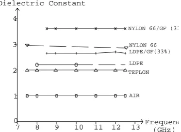
Figure 1. : Equipment Set-up for Waveguide Transmission Figure 2. : Dielectric Constants of Air, Teflon, Technique. LDPE, LDPE/GF(33%), Nylon 66/GF(33%), Nylon 66 at Room Temperature over Certain Frequencies.
THEORY OF WAVEGUIDE TRANSMISSION TECHNIQUE
The idea of calibration was to get the values of reflected and transmission coefficients with air filled waveguide as standard and then compare the values of those with sample filled ones. During measurements, fixed lengths of waveguide were filled with the FRTP and a range of waveguide sizes was required to cover an almost continuos spectrum of frequencies from 2.2 - 12.5 GHz. The transmission coefficient between the reference planes is7 :
4Γ1Γ0
S21 = ---
(Γ1+Γ0)2exp(Γ1L) - (Γ1-Γ0)2exp(-Γ1L) (1)
where Γ0 = jβ0, the propagation coefficient in air filled waveguide
Γ1 = α1 + jβ1, the propagation coefficient in sample filled waveguide
L is the sample length in mm. The relative permittivity of the FRTP7 is :
ε = ε′ - jε″ = ε′(1 - jtan δ) (2)
For non-magnetic materials the elements of the complex permittivity may be obtained from the propagation coefficient as follows7 :
ε = [1 + (β12 - α12)(a/π)2](c/2af)2 (3)
and tan δ = α1β1c2/(2π2f 2ε′) (4)
where ‘a’ is the broad dimension of the waveguide and ‘c’ is the velocity of electromagnetic waves. Since S21 is known from measurements, in principle, (1) can be solved for Γ1, from
which the complex permittivity of the sample may be calculated. Ness6, Sabburg7 and Ball13 detailed an iterative technique for getting very accurate estimates of ε′. In this study, however, Newton’s Method which is fast-converging and very robust was used. It requires an initial estimate of ε′ and ε″ at a particular frequency. Because there are an infinite number of possible solutions, an accurate initial estimate of ε′ and ε″ is important, as it enables the iteration process to converge promptly to the required result. Occasionally, the software failed to estimate the initial value of ε′ and ε″ and the programme did not converge. In this situation, a manual estimate would be required and the software would then calculate the values of ε′ and ε″ at a range of frequencies dedicated to that particular type of waveguide.
WAVEGUIDE SIZES AND SAMPLE LENGTHS
In order to cover the frequency range of 2.2 to 12.5 GHz, four different sizes of waveguides were used, namely : WR90, WR159, WR229 and WR340. Taking waveguide WR340 as an example, the recommended range of frequencies14 for single (TE10)mode only is from 2.2 to 3.3
GHz. If the loss tangent is not excessive then the wavelength in the sample depends only on the sample relative permittivity or dielectric constant, ε′, as15 :
λo 1
λg≈ --- --- (5)
ε′1/2 [1 - (λo /2aεr1/2)2]1/2
where λo is the free space wavelength
and ‘a’ is the broad side waveguide dimension. Assuming the largest possible frequency, ie frequency = 3.3 GHz, λo = 30/3.3 = 9.091 cm and a = 3.4 x 2.54 cm = 8.636 cm. Assuming
that the dielectric constant of the sample would lie in the range of 2 to 5 and say, ε′ = 2 then (5) yields λg = 6.926 cm. For each waveguide size, it was necessary for the samples to be at least
three quarters of a guide wavelength long at the highest frequency. This allows the software to obtain sufficient S21 phase data to provide an initial estimate of permittivity. The required
sample length cannot be determined in advance so it is necessary to make worst case assumptions. The sample length required to determine various dielectric constants are as shown in Table 1.
WR 340 WR 229 WR159 WR 90
Fre range : 2.2 - 3.3 GHz 3.3 - 4.9 GHz 4.9 - 7.05 GHz 8.2 - 12.4 GHz
Permittivity Sample Length Permittivity Sample Length Permittivity Sample Length Permittivity Sample Length
2 52 2 35 2 24.5 2 14
3 41.5 3 28 3 19.5 3 11
4 35.5 4 25 4 17.2 4 9.4
5 31.5 5 22 5 15.1 5 8.5
Table 1. : Waveguide Type, Frequency Range and Sample Length
RESULTS
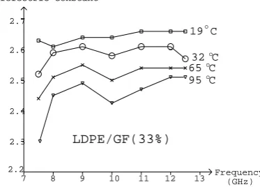
were measured at room temperature. Figure 2 shows that dielectric constants for air and teflon are 1 and 2 respectively at room temperature which coincides very well with data in the literature. This figure also illustrates the dielectric constants of polystyrene (PS) , low density polyethylene (LDPE), glass fibre-reinforced LDPE and carbon fibre-reinforced PS. Figures 3 and 4 show that the higher the temperatures the lower the values for the dielectric constant of LDPE/GF(33%). The dielectric loss of this material is quite low, of the order of 0.02 at 8 Ghz. It has not yet been possible to determine the variation of this over the 8 - 12 GHz band with sufficient accuracy because the same loss is of the order as waveguide wall loss and unpredictable coupling flange losses. However it does appear to increase with frequency and temperature , and is of the order of 0,1 at 12 GHz.
Dielectric Constant
LDPE/GF(33%) 2.4
2.6
7 8 9 10 11 12 13 Frequency(GHz) 2.3
2.5 2.7
2.2
19 C
32 Co o
65 Co
95 Co
2.5 2.6
[image:4.595.315.520.219.363.2]30 40 50 60 70 80 90 100 Dielectric Constant LDPE/GF(33%) 2.7 2.2 2.3 2.4 20 7.5 GHz 10 GHz 12.5 GHz o TEMP. ( C)
Figure 3. : Dielectric Constants of LDPE/GF(33%) Figure 4. : Dielectric Constants of LDPE/GF(33%) at Elevated Temperatures over Certain at Different Frequencies over a Range of
Frequencies. Temperatures.
Dielectric Constant
7 8 9 10 11 12 13 Frequency(GHz) 3.4
3.5 3.6 3.7 3.8
19 Co
31 Co
55 C
o
90 C o
NYLON 66/GF(33%)
30 40 50 60 70 80 90 100 Dielectric Constant
20 TEMP
( C)o
[image:4.595.94.281.227.361.2]3.5 3.4 3.6 3.7 3.8 3.9 7 GHz 10 Gz 12.5 GHz NYLON 66/GF(33%)
Figure 5. :Dielectric Constants of Nylon 66/GF(33%) Figure 6. : Dielectric Constants of Nylon 66/ at Elevated Temperatures over Certain GF(33%) at Different Frequencies over a Range Frequencies. of Temperatures.
microwave energy penetration will not be optimum. A compromise for the values of tan δ and
ε′ should therefore be chosen to obtain greatest microwave energy penetration and maximum energy conversion to heat. Similar arguments can be made for the LDPE/GF(33%) and welding the material by microwave energy at 12.5 GHz ( see figures 3 and 4) and 90 degrees Celsius will not give the optimum result because although tan δ is maximum at this frequency, ε′ is not favourable for the penetration of microwave energy.
7.5 8.5 9.5 10.5 11.5 12.5 10
20 30 40 50 60 70 80 90 110 100
31 Co
Dielectric Loss Factor
Frequency (GHz) 45 Co
67 Co
90 Co
NYLON 66/GF(33%)
(1 x 10 )-3
10
20 30 40 50 60 70 80 90 110
100
Dielectric Loss Factor
NYLON 66/GF(33%)
30 40
20 50 60 70 80 90
7 GHz
12.5 GHz
10 GHz (1 x 10 )
[image:5.595.295.481.171.353.2]Temperature ( C)o -3
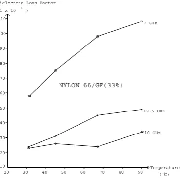
Figure 7. :Dielectric Loss Factors of Nylon 66/ Figure 8. : Dielectric Loss Factors of Nylon 66/ GF(33%) at Elevated Temperatures over Certain GF(33%) at Different Frequencies over a Range Frequencies. of Temperatures.
CONCLUSION
Information on the microwave dielectric properties of fibre-reinforced thermoplastics is required in order to determine whether they are suitable for microwave processing. Some preliminary data has been presented for 33% glass fibre reinforced LDPE and nylon 66. Those values give a clue on how to choose suitable combinations of parameters for joining glass fibre or carbon fibre thermoplastic materials using microwave energy. The potential benefits of the technology will be to speed up the replacement of thermosetting resins by advanced thermoplastic composites in the structural parts of aeronautical, military and recreational industries.
ACKNOWLEDGEMENT
The authors would like to thank Mr. Chan Ka-hau, Peter for his assistance in collecting some of the data.
REFERENCES
1. Osswald, T.A. and Menges, G, Materials Science of Polymers for Engineers, Hanser/Gardner Publications Inc., 1995, pp. 393-5.
2. Lynch, C.T. (Ed.), CRC Handbook of Materials Science, Volume III, Non-metallic Materials and Applications, CRC Press Inc., 1975, pp.118 - 120.
4. Ku, S H, Siores E, and Ball J A R (1997) Weldability and Heat Affected Zone (HAZ) Evaluation for High Energy Rate Joining of Thermoplastic Composites Using Microwave, Proceedings of the Eleventh International Conference on Composite Materials, Vol 6, pp 55-64, Gold Coast Australia, 14-18 July.
5. Ku, S H, Siores E, and Ball J A R (1997) Welding of Thermoplastic Composites Using Microwave Energy, Proceedings of CIPR International Symposium, Vol 2, pp 612-9, Hong Kong, 21-22 August.
6. Ness, J., Broadband Permittivity Measurements at Microwave Frequencies, IREE Conf. Dig., (Australia), September 1983, pp. 330 - 2.
7. Sabburg, J, Ball, J.A.R. and J.B. Ness, Broadband Permittivity Measurements of Wet Soils, Proceedings of 1992 Asia-Pacific Microwave Conference, Adelaide, pp.607 - 10.
8. Senko, H., Investigation Into and Control of Microwave Induced Thermal Run- away, PhD Thesis, Deakin University, Australia, Feb 1997.
9. HP85070A Dielectric Probe Kit, 200 MHz to 20 GHz, Hewlett Packard Product 85070A Information, August 1990.
10. Sequeira, H.B., Extracting ε and μ of Materials from Vector Reflection Measurements, Microwave Journal Vol. 34 No. 3, March 1991, pp. 73 - 85.
11. Pham, A.T., In-situ Materials Permittivity Measurement Using a Monopole Antenna, Proc. IREE Conv., (Australia), Sept. 1991, pp. 658 - 61.
12. Ness, J., Broadband Permittivity Measurements Using the Semi-automatic Network Analyser, IEEE Trans. Microwave Theory Tech., Vol. MTT-33, No.11, November 1985, pp.1222 - 6.
13. Ball, JAR, Horsefield, B and et al, Cheese Curd Permittivity and Moisture Measurement Using A 6-Port Reflectometer, Proceedings of 1997 Asia-Pacific Microwave Conference, Dehli, India.
14. HP Coaxial and Waveguide Catalogue and Microwave Measurement Handbook, 1993.