UNIVERSITI TEKNIKAL MALAYSIA MELAKA
ELECTRIC PROFLER SYSTEM USING ARDUINO
This report submitted in accordance with requirement of the Universiti Teknikal Malaysia Melaka (UTeM) for the Bachelor’s Degree in Computer Engineering
Technology (Computer Systems) (Hons.)
by
NUR MASTURINA BINTI ROSLAN
B071310611
940309035448
DECLARATION
I hereby, declared this report entitled “Electric Profiler System using Arduino” is the results of my own research except as cited in references.
Signature : ... Author’s Name : Nur Masturina Binti Roslan
3
APPROVAL
This report is submitted to the Faculty of Engineering Technology of UTeM as a partial fulfilment of the requirements for the degree of Bachelor’s in Computer Engineering Technology (Computer Systems) (Hons.). The members of the supervisory committee are as follow:
……… (HASRUL’NISHAM BIN ROSLY)
4
ABSTRAK
5
ABSTRACT
6
DEDICATION
Every challenging works need self-efforts as well as guidance of elders, especially those who were very close to our heart.
My humble effort I dedicate to my sweet and loving
Father & Mother,
Whose affection, love, encouragement and prayers of day and night make me able to get such success and honour
Along with all hardworking and respected
7
ACKNOWLEDGEMENT
This project praises to the Almighty God for giving me the grace, courage and strength to complete it. I am very thankful to my parents for their love, support and encouragement and for being with me on each and every step of my life.
I wish to express my deepest appreciation to my supervisor, Mr. Hasrul’Nisham Bin Rosly for his idea, guidance, motivation and help throughout my project, Electric Profiler System using Arduino which is part of the Final Year Project required for Bachelor’s Degree in Computer Engineering Technology (Computer Systems) with Honours. I feel thankful to him for his insightful advice and suggestions. Without his support and guidance, it is impossible for me to complete my project successfully. Special thanks also to my co-supervisor, Mrs. Rosziana Bin Hashim for her constructive criticisms and guidance which helped me in achieving better project development.
8
Abstract i
Table of Content ii
List of Tables iii
List of Figures iv
CHAPTER 1: INTRODUCTION 1
1.1 Background 1
1.2 Problem Statement 1
1.3 Objectives 2
1.4 Scope 3
1.5 Outline 4
1.6 Conclusion 5
CHAPTER 2: LITERATURE REVIEW 6
2.1 Introduction 6
2.1.1 Arduino 7
2.1.2 ACS712 current sensor 8
2.1.3Real Time Clock (RTC) chip 11
2.1.4 Liquid Crystal Display (LCD) 1602 12
2.1.5 I2C serial bus 12
2.1.6 Smart Meter Energy 13
2.2 Past Related Researches 15
2.2.1 Findings by others and similar projects 15
2.3 Summary 18
CHAPTER 3: METHODOLOGY 19
3.1 Project Development Process 19
3.2 The Architecture of System 21
3.3 Design Components 22
9
3.3.1 Arduino Board 22
3.3.2 Arduino Proramming 22
3.3.3 Flowchart 23
3.3.4 Prototyping methodology 25
3.4 Hardware Design 26
3.4.1 Arduino Board 26
3.4.2 ACS712 Current Sensor 27
3.5 Software Design 28
3.5.1 Arduino program for Arduino Board 28
3.5.2ACS712 Current Sensor programming 29
3.6 Electric Profiler 30
3.7 Budget and costing 30
3.8 Summary of Methodology 31
CHAPTER 4: RESULT AND DISCUSSION 32
4.1 Introduction 32
4.2 Development of Phase 32
4.3 Hardware Implementation 32
4.3.1 ACS712 Current Sensor 33
4.3.2 Arduino UNO and ACS712 current sensor 34
4.3.3 Arduino UNO and real time clock 36
4.4 Software Implementation 37
4.5 Result 38
4.6 Coding Implementation 39
4.6 Discussion 42
4.6.1 Limitation of study 42
4.6.2 Problem Encountered 42
CHAPTER 5: CONCLUSION 43
5.1 Introduction 43
5.2 Conclusion 43
10
5.4 Project Potential 45
REFERENCES 46
APPENDICES 49
A Gantt Chart 50
B Coding of ACS712 Current sensor 51
C Coding of real time clock 52
D Coding of LCD1602 display with I2C serial 53
11
LIST OF TABLES
2.1 Comparison between single and three phase of power meter pulse 10
2.2 Comparison utility meters 14
2.3 The summary of research of literature review 17
3.1 Direct cost of electric profiler system 30
4.1 Pin connection of ACS712 current sensor 34
12
LIST OF FIGURES
1.1 Project Block Diagram of Electric Profiler 3
2.1 Project Block Diagram of Electric Profiler 6
2.2 Arduino UNO 7
2.3 ACS712 Current Sensor 8
2.4 Illustration of Half Effect Principle 9
2.5 Connection configuration of ACS712 current sensor with Arduino, load and power supply
10
2.6 Front of Real Time Clock 11
2.7 Back of Real Time Clock 11
2.8 LCD display 1602 12
2.9 I2C serial of LCD display 12
2.10 I2C serial is attached with LCD 13
2.11 How the smart meter works 13
3.1 3.2
Overview Architecture
Flowchart of the Electric profiler system part1
21
3.3 Flowchart of the Electric profiler system part2 24
3.4 Prototyping methodology 25
3.5 Block Diagram of electric profiler 26
3.6 Arduino Board 26
3.7 Interfacing Arduino UNO and ACS712 current sensor 27 3.8 Example of Arduino code of myMultiiplyFunction( ) 28 3.9 Example of ACS712 current sensor 29
4.1 ACS712 Current Sensor 33
4.2 Arduino UNO connected to the CAS712 current sensor 34 4.3 The connection between Arduino UNO, ACS712 current sensor
and wire
35
4.4 The connection between Arduino UNO and RTC 36
13 4.6 The front of the electric profiler system device 38
4.7 The electric profiler system device 38
4.8 Coding of ACS712 current sensor 39
4.9 Coding of real time clock 40
4.10 Coding of LCD with i2C serial 41
14 CHAPTER 1
INTRODUCTION
This chapter discussed about the background, problems statement, objectives and scope of the project.
1.1BACKGROUND
Electric profiler system is a project that displays the total amount of the electric bill to users in kWh or kW. By using this system, the user will know the amount of the electric bill used accurately without need to predict the amount to pay every month. Thus, ACS712 current sensor is uses to measure the current or electric that flow through the plug. Then, Arduino get the data and the current is converted to price in Ringgit (RM) and it will be displayed at the computer.
1.2PROBLEM STATEMENT
This project is an alternative way to overcome the billing system. Normally, user needs to wait until the end of the month to know the amount of the electric bill from Tenaga Nasional Berhad (TNB). There are several disadvantages of this system. Lately, the officers check the current meter by assuming the meter from far. It is either he is bothers to ask permission from the user to look at the meter or lazy to ask. Due this problem, the officers assume the meter higher than the actual meter that cause the higher bill for user. They do not bother the amount of bill because the users pay the bill.
15 Tenaga Nasional Berhad (TNB) to rob and rape. This makes the officers duty more difficult without the user cooperation.
Thus, to avoid this kind of problems, the electric profiler system created. By using this device, the users can calculate the electricity by themselves manually. The electric profiler device is easier to control the power consumption. Through this device, users can monitor the electricity consumption every day and every moment. When the user feel the usage of electricity is uncontrolled, they can decrease the usage of electricity. Being able to monitor the electricity consumption provides extremely valuable insight in the effort to conserve the energy.
1.3OBJECTIVES
Objectives are the goals to be achieved at the end of the project or study. Each project has objectives that keep the project on the right path and become more clearly to define. There are only two objectives that are determined of this project and required to be achieved. The objectives of this project are as below:
1. To study electricity system and rate in Malaysia
2. To design the electric profiler system device using Arduino 3. To implement electric profiler system in daily usage
For the first objective, this project is to study electricity system and rate in Malaysia. This can help how to calculate the power consumption used using the tariffs of Tenaga Nasional Berhad (TNB)
16 1.4SCOPE
This project is the electric profiler system using the ACS712 current sensor to detect the current flow. The scope of work for this project is to cover cases study through literature reviews and journals on the Arduino UNO microcontroller and ACS712 current sensor.
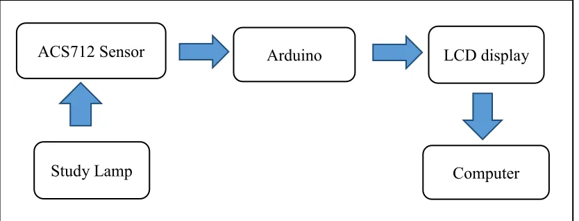
[image:16.612.125.542.282.441.2]In addition, the scope of this project is development of electric profiler system. Users can monitor the electricity in certain time they want. Furthermore, this project will be focused on two features which are software and hardware part.
Figure 1.1: Project Block Diagram of Electric Profiler
Firstly, the software part is responsible to make the programming code for the Arduino circuit. For the coding, the C++ AND Java will be used where the Arduino software is in C++ programming.
In hardware part, the ACS7712 current sensor is uses to measure the current or electric that flows then, Arduino get the data and the current is converts to price in Ringgit (RM) and it will be display at the computer. Arduino is the open source that is easy and simple to be used for building the electronics projects. Arduino also consists both of the microcontroller which is the physical circuit and software, or IDE (Integrated Development Environment) that runs on the computer, which is used to write and upload computer code to the physical board.
ACS712 Sensor Arduino
Computer Study Lamp
17 1.5OUTLINE
This project is consists of five chapters. In chapter I, the project overview the objective, scope of work and problem statement that are briefly discussed which purposely to provide the understanding of the project introduction.
Chapter II, the related researches as literature review of the project which includes the concept, theory, perspective, and the method of the project that is used in order to solve the problem occurs and any other that related with the research of methodology.
Chapter III is about the research methodology of the project. This chapter will discuss the method or approach that used in project development.
Chapter IV is the discussion on the observation, result and the analysis of the project during the development of project. This chapter also consists of the recorded data analysis and the result of the project.
Chapter V covers the discussion of whole contents of the thesis and project development.
18 1.6CONCLUSION
19 CHAPTER 2
LITERATURE REVIEW
In this chapter, the theory will be discussed regarding this project, which reveals the knowledge that gained via resources from reference book, journal, articles, newspapers, and websites that contain application, research work, and related theories. The study is very necessary in order to gain more knowledge and understanding of smart energy meter, Arduino, ACS712 Current Sensor and related research, and existing technology of research that contains similarity to the project. This chapter presents a review of related works in the electric profiler using Arduino.
2.1 Introduction
[image:19.612.124.532.546.704.2]Electric profiler is known as a device to measures the power consumption that has been used. By measuring the power consumption is the way to save cost. Every house of the residence has a house meter that shows the total power consumed. Furthermore, the house meter is placed where the officer is convenient to read. This electric profiler can help user to measure and record the electricity in the house. The simple electric profiler requires Arduino circuit and ACS712 current sensor for more convenient to received and display the information. Some house meters record data every second but using the sensor the data recorded min every 30 seconds.
Figure 2.1: Block diagram of electric profiler ACS712 Sensor
Study Lamp
Arduino
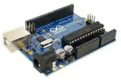
20 2.1.1 Arduino
Figure 2.2: Arduino UNO
Arduino was created at the Ivrea Interaction Design Institute as an easy component or circuit that fast prototyping aimed for students without the background in electronics and programming. Arduino is the open source prototyping that easy to use in hardware and software. Arduino are able to read input, the light sensor, finger on the button and turn it into an output activating a motor, light on the LED or publishing online. But, Arduino programming language and the Arduino software ( IDE ) required to use. The Arduino software is easy to use for beginners where it runs on Mac, Windows and Linux.
21 This project uses Arduino UNO microcontroller because it is relatively cheap, plugs straight into the computer’s USB port and simple to setup and use compare to other development boards. It is an open source design that many people is used and easy to find someone to help debug the project. The Arduino board is designed as circuit board for programming and prototyping with Atmel microcontrollers. There is button to reset the program on the chip.
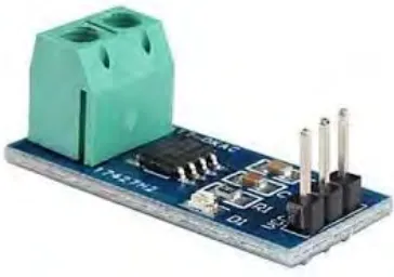
[image:21.612.254.436.259.387.2]2.1.2 ACS712 Current Sensor
Figure 2.3: ACS712 Current Sensor
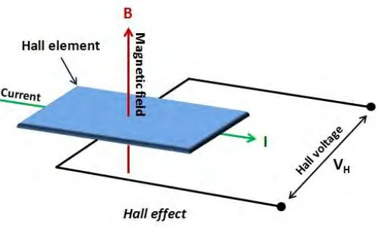
22 Figure 2.4: Illustration of Hall Effect principle
Hall element is the thin sheet of semiconductor carrying the current (I) and placed into the magnetic field (B) that perpendicular to the direction of current flow. There is the presence of the Lorentz Force so, the distribution of current is no more in uniform that across the Hall element. Thus, the potential difference across the edge of the perpendicular is created to the directions of both current and field that known as Hall Voltage. The value is in the order of the microvolts. The Hall Voltage is directly proportional to magnitudes of current (I) and magnetic field (B) thus, either current (I) or magnetic field (B) is determined, the Hall Voltage can estimate the other.
ACS712 current sensor provided in a small size, it surface mount SOIC8 package. It consist linear Hall sensor circuit with copper conduction path that located near the surface of the die, low off-set and precise. The ACS712 current sensors are designed to use with the Arduino microcontroller easily. This sensor is based on the Allegro ACS712ELC chip.
Advantages of ACS712 current sensor:
- ACS712 current sensor is Half effect sensor
- Nearly not affect the measured current
23
- Considered non-intrusive because no significant amount of resistance is inserted into the current path, and thus the circuit being measured behaves almost as if the sensor is not present
- Regarding accuracy, currently available Hall effect sensors can achieve output error as low as 1%
- Can be used for both AC and DC current measurement
Single phase power meter pulse sensor Three phase power meter pulse sensor
Usually each pulse equals one Wh (1000 pulses per kWh )
Each pulse corresponds to greater amount of energy
Generally the cheapest and easiest way to collect energy data, because they can be attached to existing smart meters
[image:23.612.126.540.214.331.2]Generally the cheapest and easiest way to collect energy data, because they can be attached to existing smart meters
Table 2.1: Comparison between single and three phase of power meter pulse
ACS712 current sensor can detect both AC and DC current and designed for three current ranges which is 5A, 20A and 30A. ACS712 current sensor consists of integrated circuit that works used the half effect principle.
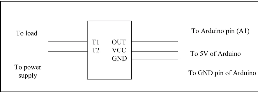
Figure 2.5: connection configuration of ACS712 current sensor with Arduino, load and power supply.
TI and T2 pin at the ACS712 current sensor need to connect in series with the current path to detect the current later. OUT pin is connects to the analog input pin on the Arduino board
T1 OUT T2 VCC GND
To Arduino pin (A1)
To 5V of Arduino
To GND pin of Arduino To load
[image:23.612.108.551.450.610.2]24 while VCC is connects to the 5V pi on the board and GND is connected to GND on the Arduino.
2.1.3 Real Time Clock (RTC) chip
Figure 2.6: Front of Real Time Clock Figure 2.7: Back of Real Time Clock