This is a repository copy of
Active Harmonic Current Elimination and Reactive Power
Compensation using Modular Multilevel Cascaded Converter
.
White Rose Research Online URL for this paper:
http://eprints.whiterose.ac.uk/117543/
Version: Accepted Version
Proceedings Paper:
Huang, H, Oghorada, OJK, Zhang, L et al. (1 more author) (2017) Active Harmonic Current
Elimination and Reactive Power Compensation using Modular Multilevel Cascaded
Converter. In: EPE 2017 ECCE Europe. 19th European Conference on Power Electronics
and Applications, 11-14 Sep 2017, Warsaw, Poland. IEEE . ISBN 978-90-75815-27-6
10.23919/EPE17ECCEEurope.2017.8098966
© assigned jointly to the European Power Electronics and Drives Association & the
Institute of Electrical and Electronics Engineers (IEEE). This is an author produced version
of a paper published in 19th European Conference on Power Electronics and Applications
(EPE 2017 ECCE Europe). Personal use of this material is permitted. Permission from
IEEE must be obtained for all other uses, in any current or future media, including
reprinting/republishing this material for advertising or promotional purposes, creating new
collective works, for resale or redistribution to servers or lists, or reuse of any copyrighted
component of this work in other works. Uploaded in accordance with the publisher's
self-archiving policy.
[email protected] https://eprints.whiterose.ac.uk/ Reuse
Unless indicated otherwise, fulltext items are protected by copyright with all rights reserved. The copyright exception in section 29 of the Copyright, Designs and Patents Act 1988 allows the making of a single copy solely for the purpose of non-commercial research or private study within the limits of fair dealing. The publisher or other rights-holder may allow further reproduction and re-use of this version - refer to the White Rose Research Online record for this item. Where records identify the publisher as the copyright holder, users can verify any specific terms of use on the publisher’s website.
Takedown
If you consider content in White Rose Research Online to be in breach of UK law, please notify us by
Active Harmonic Current Elimination and Reactive Power Compensation
using Modular Multilevel Cascaded Converter
H. Huang, O. J. K Oghorada, L. Zhang, B.V.P Chong
UNIVERSITY OF LEEDS
School of Electronic and Electrical Engineering, University of Leeds
Leeds, United Kingdom
E-Mail:
[email protected]
.
URL:
http://www.leeds.ac.uk.
Keywords
«Active filters», «Pulse width modulation», «Modular multilevel converters», «Reactive power control».
Abstract
This paper presents a new application of modular multilevel cascaded converters (MMCC) for combined active harmonic current elimination and reactive power compensation in a power distribution line. A technique for simultaneous extracting harmonic components and reactive element in the load current is presented. A novel voltage control scheme for balancing the module intra-cluster capacitor voltages under distorted load current is incorporated. Simulation studies show the desired performance of the MMCC-based active power conditioning operating under PCC current distortion and varying load conditions.
Introduction
The development of power semiconductor switching devices and micro-electronics in recent decades has led to the widespread use of power electronic controlled equipment. Products such as variable speed drives, switch mode power supplies are familiar for domestic and industrial applications, which have brought the benefit of ease of control and improved energy efficiency. The current surge in developing renewable energy sourced generators presses the further demand for power converters. However one of the issues with power converters is their drawing of non-sinusoidal current from the utility grid. This current may consist of both low-order (i.e. 5th, 7thand 11th) and/or high-order harmonics (i.e. on the order
of the converters’ switching frequencies). The former will increase the winding copper losses in the transformers installed within a power network, leading to an increased heating effect and then a reduction in the equipment lifetime. High frequency current harmonics, on the other hand, will experience a higher effective resistance and decrease the conductor current transmission capability due to heating as they tend to flow near the conductor’s surface due to skin effect [1].
Traditionally, a tuned passive filter has been applied by industries to overcome the problems with harmonics. However, it has several shortcomings including the limited compensating characteristics imposed by the filter and its ineffectiveness in regulating the amount and type of harmonics it needs to compensate [2]; for example, passive filter parameters are difficult to change dynamically in order to remove harmonics of varying frequencies [3]. To address these issues, a filtering technique through an active device or active power filter (APF) has been proposed [4]. This is largely based on a power electronic converter, with a DC link capacitor connected at its input for stabilising its operation while it is controlled to generate the current harmonics required by the load bus[5, 6]. Many well-applied DC-AC converters have been used to implement an APF and they have their own drawbacks. For example, conventional H-bridge converters suffer a high amount of voltage stress while multilevel converters can become more complex in circuitry and control for high-voltage and power applications.
[7-11]. With its modularity, reliability and feasibility [12], an MMC based on several units of cascaded converters is applied, in this paper, as an active power conditioner (MMCC-APC) for both harmonic current elimination and power factor control. To meet the line voltage levels with less harmonic distortion and switching losses, the MMCC-APC has four cascaded full H-bridge converters in each limb and each H-bridge has its own DC capacitor [13].
For effective current control function a technique for simultaneous extracting harmonic components and reactive element in the load current is presented. A novel multilevel PWM scheme called carrier-swapped PWM method is described which is shown to be effective for balancing the MMC intra-cluster capacitor voltages under distorted load current. The latter is necessary in this application because the current harmonics flowing through the H-bridge sub-modules lead to voltage drifts away much more significant compared to other applications such as those used in an HVDC system. A comparison between the results from using the CS-PWM and that by traditional phase shift-PWM (PS-PWM) will be made based on a current harmonics control application. This MMCC-APC is also designed to correct the system’s power factor.
The paper is structured by giving the MMCC-APC configuration in section 1; its harmonic extraction and control principles are described in section 2. This is followed by the MMCC PWM schemes. Simulation study and result discussions are finally presented.
MMCC-based APC System
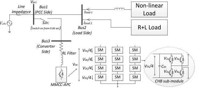
The configuration of the MMCC-APC and its connected network is shown in Fig. 1. This has been designed specifically to mitigate the impacts of connecting a non-linear load and a normal inductive load at Bus 2, though in reality many parallel loads would be present. To achieve this, the MMCC-APC is designed to improve the waveform quality of the current drawn from the incoming feeder which is represented byVabc, and obtaining unity power factor simultaneously at Bus 1 which has been assigned as the point of common coupling (PCC).
Vabc RL Filter Bus1 (PCC Side) Bus2 (Load Side) MMCC-APC Non-linear Load VDC
VDC/4 SM
SM SM SM SM SM SM SM SM SM SM SM VDC/4
VDC/4
VDC/4
CDC
V1a
VDC/4
V2a V3a V4a CHB sub-module Bus3 (Converter Side) SAPC
(Switch on from 0.06 sec)
Iload 2
R+L Load
Iload 1
Line impedance
[image:3.595.127.474.440.595.2]Vpcc
Fig. 1 Circuit configuration of MMCC-APC
The MMCC configuration is also shown in Fig. 1; it is a three-phase star configuration where each phase arm is a chain of four cascaded H-bridge converters, referred to sub-modules (SMs). Each SM contains four transistors and a DC capacitorCDCat a nominal voltage of . So each chain can synthesize nine voltage levels (0, ±0.25 , ±0.5 , ±0.75 ,± ). With multiple modules in series each only switches at a reduced frequency, hence having low switching losses, and a high total voltage can be attained. In practice the number of SMs may be a lot higher determined by the PCC voltage magnitude and the per module DC-link voltage.
when the latter is used. The switch,SAPC, is the circuit breaker of the MMCC-APC. The harmonic and reactive currents caused by the load will be compensated by the MMCC-APC, in order that the PCC side current approximates to the ideal sinusoidal with unity power factor. The specifications of all the parameters used in a simulated specimen system are summarised in Table I.
Control Schemes
The overall control scheme for the MMCC-APC system is shown in Fig. 2 and is divided into four main parts; reference current generation, modified model-based predictive current control, SM capacitor voltage balance control and novel multilevel pulse width modulation scheme.
VDC_avg
(VDC_a+VDC_b+VDC_c)/3
.. . VDC_1
VDC_2
VDC_12
PI
Load current
Iload i
d_ref
iq_ref
Predictive Control Block VDC_ref Vsh_d* Vsh_q* Low Pass Filter -+ abc
dq Ih_d*
Idc
+ +
SM capacitor voltage balancing control MMCC reference current generation Modified predictive control from PLL Multilevel Pulse Width Modulation dq abc from PLL Vref_a Vref_b Vref_c m_a m_b
m_c +
-+ -+
-Fig. 2: Control blocks of the APC system
MMCC reference current generation
The technique operates by firstly transforming the measured load currentIloadinto a synchronous rotating reference frame (SRRF) via Park transformation, taking the PCC voltageVpccas reference. This leads to
IdandIqgiven as:
=
sin( ) sin( ) sin( + )
cos( ) cos( ) cos( + ) (1)
where is the phase angle of PCC voltage obtained through a phase-locked loop (PLL) synchronisation
scheme. Note that through the above transformation, IdandIq, in general, will contain a set of (h– 1) order harmonics whereh is the order of harmonics present inIa,IbandIc. It is desirable that IdandIq only contain DC components, implying thatIa,IbandIconly contain the grid fundamental frequency . Therefore, the first-order Low-Pass Filter (LPF) is applied to the transformed current in order to remove its AC quantities. Its transfer function is given in Fig. 2 and the cut-off frequency2 is chosen to be
slightly lower than 2 so that the high order harmonics can be effectively eliminated. It must not be too
[image:4.595.123.475.200.359.2]low also so that a steady state is quickly achieved after this the system has to re-adjust its operation in response to a change in the load.
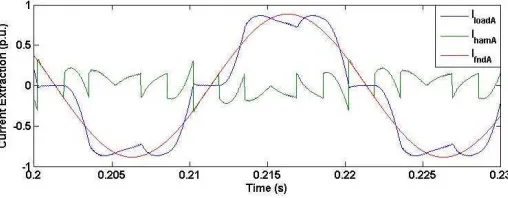
Fig. 3 Current harmonics extraction from phase A load current
[image:4.595.171.425.628.727.2]q-component. The extracted harmonic current from phase A load current is shown in Fig. 3. For the reactive power control, the desirableIa,IbandIcshould be in phase with the three phase PCC voltages and thus the q-component in (1) is taken as the reactive current reference for the converter current controller without filtering.
Modified predictive control
The predictive controller is based on the grid-connected converter’s space vector equation given by
= + (3)
When implemented in a real digital system, a small sampling period ( ) is chosen and is expressed by
= = ( ) ( ) (4)
whereTSis defined as the time betweenkthand (k+1)thsamples. Since the next sampling period current
( + 1)cannot be known in advance, so it is replaced by the current reference value ( ). After substituting (4) into (3) and doing re-arrangement, the required reference voltage at the next sampling period can be derived as (5) and the completed d-q voltage equations are given as (6).
( ) = ( ) ( ) + [ ] ( ) (5)
_ ( ) = _ ( ) ( ) + ( ) ( )
_ ( ) = _ ( ) ( ) + ( ) + ( )
(6)
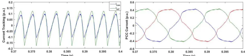
The is regarded as the set point for the MMCC and is used for generating the PWM signals. Using this the converter reference current tracking and the corresponding PCC current after harmonic extraction are shown in Fig. 4(a) & (b) which are not desirable.
Fig. 4(a) Converter current reference tracking and (b) Three phase PCC current without modification
There is clearly a tracking error between the converter and reference currents especially when load current changes sharply, which causes the three phase PCC current being distorted. This is due to a delay stemming from the predictive controller’s inherent feature, since the value of ( + 1)is set to its current value, this imposes a 1-sample delay to the control action. Also the necessary use of LPF incurs further delay. In order to compensate the delay effect, the control scheme in (5) is modified. This is done by using the reference current at (k-1) sample and comparing it with the present, the difference between the two may be obtained. The rate-of-change of this reference current is calculated. This derivative term is added to the original reference value to produce a new reference current for the compensator, as shown below.
[image:5.595.80.513.496.595.2]
The equation shows a coefficient being used to scale the derivative. The value of needs to be carefully chosen for achieving the desired compensation effort. In this study a < 1 was found to be sufficient in all cases. Substituting the new reference current expressed by (7) into (6) the voltage reference equations are derived as (8).
_ ( ) = _ ( ) + ( ) + ( ) + ( ) ( )
_ ( ) = _ ( ) + ( ) + ( ) + ( ) + ( )
(8)
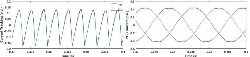
With this modified formulae the reference current tracking and the resultant PCC current as shown in Fig. 5(a) and (b) are improved significantly.
Fig. 5(a) Converter current reference tracking and (b) Three phase PCC current with modification ( = 0.12)
Sub-Module capacitor voltage balancing control
The DC capacitor voltages of all modules need to be balanced, namely they should be kept within their rated levels during the operation, since some may drift away from their nominal values due to the converter switching power losses and charge and discharging pattern variations. Balancing is typically obtained by applying a module average voltage feedback control scheme as shown in (9) and (10); In this case the(4 × 3)DC capacitor voltage average value is evaluated at every sample instant as
_( )= _ ( ) (9)
where equals to the number of SM in each chain andVDC_avgis derived as
_ = _ _ _ (10)
The resultant value VDC_avg,is applied to a PI controller with the reference voltage VDC_ref, which is
determined by the nominal DC-link voltage for each SM. The output reference current signalIdcfrom this controller is added onto the _ to form the converter total reference currentId_ref.
Multilevel Pulse Width Modulation Schemes
Phase-Shift PWM (PS-PWM)
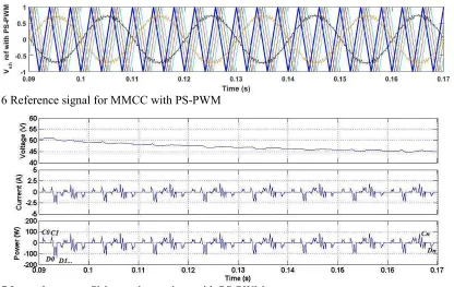
This scheme has been widely applied for multilevel converter switching control, which relies on a number of triangle carrier signals phase delaying with each other, and the number of carriers is according to SM number in each phase lime. In this work, four H-bridge SM in one phase chain so four carriers are required. The constant angle between the individual triangle carriers is
= ° (11)
[image:6.595.85.513.226.325.2]reference and its 180° anti-phase part to decide PWM switching times [14]. The first carrier applied for phase A upper first SM has been highlighted for observation as shown in Fig. 6. Though for sinusoidal application this scheme has shown being stable in maintaining sub-module capacitor voltage balance at steady-states, it cannot perform well when the converter voltage reference signal is distorted. For APC application due to the effect of generating current harmonics, the reference phase voltages are non-sinusoidal which causes significant imbalance in intra-cluster capacitor voltages’ charging and discharging states. With PS-PWM implemented, the intra-cluster capacitor voltages cannot achieve natural balancing despite additional feedback control, due to the fact that the ampere-second products are non-zero, causing the capacitor voltage drifting away.
[image:7.595.90.506.191.454.2]Fig. 6 Reference signal for MMCC with PS-PWM
Fig. 7 Intra-cluster top SM capacitor actions with PS-PWM
The capacitor voltage, charging and discharging currents and the power fluctuations for phase A upper first SM over 4 fundamental cycles from 0.09sec to 0.17sec are shown in Fig. 7. In the power plot, the states of charging and discharging this capacitor are counted as C0, C1…Cn and D0, D1…Dn, hence the energy charged into and discharged from the capacitor can be evaluated respectively. This evaluation enables calculation of the total energy flowing through the capacitor during this period as given below.
= ( ) (12)
= ( ) (13)
= + (14)
In this example during 0.09sec to 0.17sec for this capacitor is -156.74mJ. This results in the capacitor discharging and voltage decreasing gradually, as shown in Fig. 7 capacitor voltage wave.
Carrier Swap-PWM (CS-PWM)
Fig. 8 Triangle Carrier Swap-PWM method for MMCC-APC
[image:8.595.97.495.266.420.2]Using CS-PWM, as shown in Fig. 9, the charging and discharging patterns for each SM capacitor in a phase limb will be changed from cycle 1 to cycle 4 and swapped between four SM DC-link capacitors. The total charging energy for the same capacitor above is recalculated as 0.90mJ which verified the effectiveness of the new method. Hence, although the capacitor voltage drops from 0.10sec to 0.12sec, along with the carrier waveform swap, its voltage will increases back to a higher value. As a result the capacitor voltage floats around its nominal value in a small range.
Fig. 9 Intra-cluster top SM capacitor actions with CS-PWM
Simulation Results
Table I: MMCC-APC system parameters
Components Rating
Source end voltageVpcc 110 V
RL Filter 1.0 , 1.0 mH
Non-linear Load 3-phase thyristor rectifier
R+L Load 10.0 , 48.0 mH
Firing angle 0°; 30°; 60°
DC capacitorCdc 1350 F
DC voltageVdcin each sub-module 50 V
Base Voltage 110 V
Base Power 3.3 kW (for 3 phases)
Switching frequency 1 kHZ
The proposed MMCC-APC is verified through a simulation study where the APC system and corresponding control strategies are implemented via SIMULINK/MATLAB. Simulation parameters are shown in Table I;Vpccand the load are constitutive elements of a three phase balanced system; the former is rated 110V, 3.3KVA, 50Hz and the latter contains a three phase full bridge thyristor rectifier in parallel with a three phase R+L load of power factor 0.8.
expected, the absence of waveform permutation method will lead to the DC capacitors to settle down at different voltages, and the settling time is longer than that when the method is included.
Fig. 10 SM DC capacitor voltages in Phase A (a) without DC capacitor voltage balancing method (b) with DC capacitor voltage balancing method
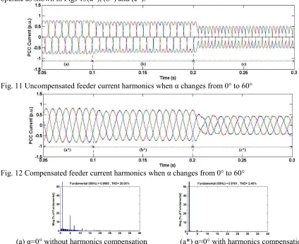
[image:9.595.70.494.396.742.2]The harmonics control performance of the APC is analysed for different load conditions, which are obtained by changing the firing angle of thyristor controlled load. Three operating scenarios are tested while the currents drawn from the source with and without harmonics control are respectively shown in Figs. 11 and 12. Starting, in both figures, the firing angle sets at 0°, the currents are seen to be distorted as shown in Fig. 11 section (a) for the case of without harmonics compensation. Meanwhile, Fig. 12 shows the APC switches on to perform filtering function in comparison with Fig. 11, the current distortions are all eliminated in section (a*). To test the adaptability of the APC, both figures are set to experience changes to 30° at 0.1 sec and 60° at 0.2 sec. Again the harmonics waveforms in Fig. 11 are all filtered in Fig.12. The corresponding harmonic spectra are shown in Fig. 13 with their THDs shown respectively in the figures. It can be observed that THD reduce significantly when the APC is set to operate as shown in Figs 13(a*), (b*) and (c*).
Fig. 11 Uncompensated feeder current harmonics when changes from 0° to 60°
Fig. 12 Compensated feeder current harmonics when changes from 0° to 60°
(b) =30° without harmonics compensation (b*) =30° with harmonics compensation
[image:10.595.91.508.66.257.2](c) =60° without harmonics compensation (c*) =60° with harmonics compensation
Fig. 13 Feeder current harmonics spectra for different simulation scenarios
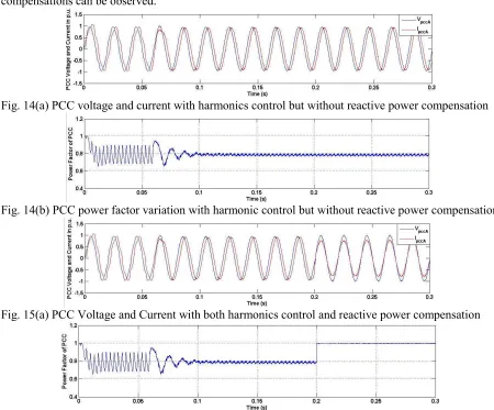
The interaction between the harmonics compensation and reactive power control is also studied for a wide range of operations. To do that, another two simulation scenarios are considered; one is only with harmonics control while the other is with both harmonics control and reactive power compensation. The APC is only introduced at t= 0.06 for both cases. The former scenario is depicted in Fig. 14 and as expected, the feeder currents are lagging the PCC voltages in (a) and power factor maintains at 0.8 as shown in (b). When reactive power control is incorporated in the APC, a unity power factor can be achieved as shown in Fig. 15(a) and (b). Also, a smooth and fast transient response for both compensations can be observed.
Fig. 14(a) PCC voltage and current with harmonics control but without reactive power compensation
Fig. 14(b) PCC power factor variation with harmonic control but without reactive power compensation
Fig. 15(a) PCC Voltage and Current with both harmonics control and reactive power compensation
[image:10.595.70.520.372.745.2]Conclusion
A combination of active power filtering and reactive power control based on MMC is proposed in this paper to cope with non-linear load and inductive load complex situation. A novel carrier swap method is implemented to avoid unbalance of sub-module capacitor voltage. Meantime, the abrupt rate-of-change on generating current harmonics is solved by modified predictive controller. The final results shows that a fast response on reactive power compensation and high quality harmonics filtering simultaneously for the system.
References
[1] A. E. Kennelly, F. A. Laws, and P. H. Pierce, "Experimental Researches on Skin Effect in Conductors,"
Transactions of the American Institute of Electrical Engineers,vol. XXXIV, pp. 1953-2021, 1915.
[2] A. Varschavsky, J. Dixon, M. Rotella, and L. Moran, "Cascaded Nine-Level Inverter for Hybrid-Series Active Power Filter, Using Industrial Controller,"IEEE Transactions on Industrial Electronics,vol. 57, pp. 2761-2767, 2010.
[3] A. Emadi, Y. Gao, and M. Ehsani,Power Electronics and Applications Series: Modern Electric, Hybrid Electric, and Fuel Cell Vehicles : Fundamentals, Theory, and Design, Second Edition (2): CRC Press, 2009.
[4] L. Zhang and L. Xiao, "A space vector-based deadbeat controller for shunt active power filters," in
EUROPEAN CONFERENCE ON POWER ELECTRONICS AND APPLICATIONS, 1997, pp.
4.864-4.869.
[5] S. Srivastava, Y. Shah, B. Shah, P. Salvi, and R. M. Patel, "Implementation and simulation of single phase active shunt power filter," in2016 IEEE 1st International Conference on Power Electronics, Intelligent Control and Energy Systems (ICPEICES), 2016, pp. 1-4.
[6] A. Bag, B. Subudhi, and P. K. Ray, "Grid integration of PV system with active power filtering," in2016 2nd International Conference on Control, Instrumentation, Energy & Communication (CIEC), 2016, pp. 372-376.
[7] M. S. Hamad, K. H. Ahmed, and A. I. Madi, "Current harmonics mitigation using a modular multilevel converter-based shunt active power filter," in2016 IEEE International Conference on Renewable Energy Research and Applications (ICRERA), 2016, pp. 755-759.
[8] G. Tsolaridis, E. Kontos, H. Parikh, R. M. Sanchez-Loeches, R. Teodorescu, and S. K. Chaudhary, "Control of a Modular Multilevel Converter STATCOM under internal and external unbalances," in
IECON 2016 - 42nd Annual Conference of the IEEE Industrial Electronics Society, 2016, pp. 6494-6499.
[9] C. J. Nwobu, I. B. Efika, O. J. K. Oghorada, and L. Zhang, "A modular multilevel flying capacitor converter-based STATCOM for reactive power control in distribution systems," in2015 17th European Conference on Power Electronics and Applications (EPE'15 ECCE-Europe), 2015, pp. 1-9.
[10] O. J. K. Oghorada, C. J. Nwobu, and L. Zhang, "Control of a single-star flying capacitor converter modular multi-level cascaded converter (SSFCC-MMCC) STATCOM for unbalanced load compensation," in8th IET International Conference on Power Electronics, Machines and Drives (PEMD 2016), 2016, pp. 1-6.
[11] O. J. K. Oghorada and L. Zhang, "Control of a Modular Multi-level Converter STATCOM for low voltage ride-through condition," inIECON 2016 - 42nd Annual Conference of the IEEE Industrial Electronics Society, 2016, pp. 3691-3696.
[12] F. Z. Peng and J.-S. Lai, "Multilevel cascade voltage source inverter with separate dc sources," Lockheed Martin Energy Syst Inc1997.
[13] L. Zhang, M. J. Waite, and B. Chong, "Three-phase four-leg flying-capacitor multi-level inverter-based active power filter for unbalanced current operation,"IET Power Electronics,vol. 6, pp. 153-163, 2013.