2015
Introduction To MIPS Assembly Language
Programming
Charles W. Kann
Gettysburg College
Follow this and additional works at:https://cupola.gettysburg.edu/oer
Part of theComputer and Systems Architecture Commons, and theSystems Architecture Commons
Share feedbackabout the accessibility of this item.
This open access book is brought to you by The Cupola: Scholarship at Gettysburg College. It has been accepted for inclusion by an authorized administrator of The Cupola. For more information, please [email protected].
Kann, Charles W., "Introduction To MIPS Assembly Language Programming" (2015).Gettysburg College Open Educational Resources. 2.
Description
This book was written to introduce students to assembly language programming in MIPS. As with all assembly language programming texts, it covers basic operators and instructions, subprogram calling, loading and storing memory, program control, and the conversion of the assembly language program into machine code.
However this book was not written simply as a book on assembly language programming. The larger purpose of this text is to show how concepts in Higher Level Languages (HLL), such as Java or C/C++, are
represented in assembly. By showing how program constructs from these HLL map into assembly, the concepts will be easier to understand and use when the programmer implements programs in languages like Java or C/C++. Concepts such as references and variables, registers, binary and Boolean operations,
subprogram execution, memory types (heap, stack, and static), and array processing are covered to clarify the decisions made when implementing HLL. Program control is presented using a mapping from structured programs in pseudo code to help students understand structured programming, and why it exists. Memory access in assembly is presented to high light the difference between references (pointers) and values, and how these impact HLL.
This book has numerous code examples, and many problems at the end of each chapter, and it is appropriate for a class in Assembly Language, or as a extra resource for a class in Computer Organization.
Keywords
MIPS, Assembly, Procedural Programming, Binary Arithmetic, Computer Organization, Computer Architecture
Disciplines
Computer and Systems Architecture | Computer Engineering | Computer Sciences | Systems Architecture
Publisher
Charles W. Kann III
Comments
Additional resources for this book at available at accessible athttp://chuckkann.com
Please contact the author [email protected] you wish to adopt this book for a course - thanks!
Creative Commons License
This work is licensed under aCreative Commons Attribution 4.0 License.
Charles W. Kann
Introduction to MIPS Assembly
© Charles W. Kann III 277 E. Lincoln Ave. Gettysburg, Pa
All rights reserved.
This book is licensed under the Creative Commons Attribution 4.0 License
Last Update: Sunday, November 06, 2016
An answer key is currently being written, and is available for the problems in this text. To request a copy of the answer key, write to ckann(at)gettysburg.edu. All requests must come from an account of a recognized educational institution, and the person requesting this material must be listed as an instructor at the institution.
This book is available for free download from:
Other books by Charles Kann
Kann, Charles W., "Digital Circuit Projects: An Overview of Digital Circuits Through Implementing Integrated Circuits - Second Edition" (2014). Gettysburg College Open Educational Resources. Book 1.
http://cupola.gettysburg.edu/oer/1
Kann, Charles W., "Introduction to MIPS Assembly Language Programming" (2015). Gettysburg College Open Educational Resources. Book 2.
http://cupola.gettysburg.edu/oer/2
Kann, Charles W., "Implementing a One Address CPU in Logisim" (2016). Gettysburg College Open Educational Resources. 3.
Forward
Given the effort of writing a book, the first question an author has to answer is “why bother?” The answer to that question is what frames the book, and what I will describe here.
Why was this book written? First because I do not believe that there is any book currently available which meets the needs I had for a text book. The first is that the can be obtained for a minimal price, or can even be downloaded for free at a number of sites on the web. I am very tired of asking students to pay over $100 per book for classes. I personally have been blessed in so many ways in this world, and I have reached a point in my career where I can take the time to produce this text as a small pay back for all I have been given. I hope that this example will help students who use the book to order their priorities as they go through life, to seek a good outside of personal monetary gain.
I realize that this text could very much use a good editing, unless I can find someone willing to donate the time to do so, I think the basic information in the book is well enough organized to make it useful, and well worth the cost of a free download.
The second reason I wrote this book is that I could not find an assembly programming book that met the need I had in teaching assembly programming. I believe that learning assembly
programming is important to every Computer Science student because the principals in assembly affect how high level languages and programs in those languages are implemented. I have purposefully structured the topics in this text to illustrate how concepts such as memory organization (static, heap, and stack) affect variable allocation in high level languages. The chapter on program control is intended to make the student aware of structured programming, which is the basis for control structures in all modern high level languages. Even arrays make more sense in a high level language once one understands how they are implemented, and why. This text is intended to be more than a book about assembly language programming, but to extend assembly language into the principals on which the higher level languages are built.
Finally writing a book is the best way to organize my own thoughts. Much of the material in this text existed for years as a jumble in my own mind. Producing slides and programs for class helped clarify the concepts, but it was when I had to provide a larger organization of the ideas that many of them finally gelled for me. Forcing yourself to explain a concept, particularly in the brutal detail of writing it out, is the best way to organize and learn things.
There are other details about this book that need to be mentioned. Because this book is
electronic, it can be released in phases. This text should be looked at in the same way as a beta software release. I know there are mistakes, but I have the ability to correct them and rerelease the text. So comments are welcome.
There is a separate set of appendices which should be available by mid-summer, 2015. I will update this forward with the URL address of those appendices once they are posted. If anyone is in real need of those appendices, I will send them in their current, incomplete, format. I can be contacted at ckann(at)gettysburg.edu.
at a school, and that the requestor be listed on the department web site for that school. Requests for this document can be made to me at the same address as for the appendices.
Contents
Chapter 1 Introduction ... 14
Chapter 1. 1 Binary Numbers ... 14
Chapter 1.1. 1 Values for Binary Numbers ... 14
Chapter 1.1. 2 Binary Whole Numbers ... 15
Chapter 1. 2 Converting Binary, Decimal, and Hex Numbers ... 17
Chapter 1.2. 1 Converting Binary to Decimal ... 17
Chapter 1.2. 2 Converting Decimal to Binary using Binary Powers ... 17
Chapter 1.2. 3 Converting Decimal to Binary using Division ... 18
Chapter 1.2. 4 Converting between binary and hexadecimal ... 19
Chapter 1. 3 Character Representation ... 20
Chapter 1. 4 Adding Binary Whole Numbers ... 22
Chapter 1. 5 Integer Numbers (2's Complement) ... 22
Chapter 1.5. 1 What is an Integer ... 22
Chapter 1.5. 2 2's complement operation and 2's complement format ... 23
Chapter 1.5. 3 The 2's Complement Operation ... 23
Chapter 1.5. 4 The 2's Complement (or Integer) Type ... 24
Chapter 1. 6 Integer Arithmetic ... 25
Chapter 1.6. 1 Integer Addition ... 25
Chapter 1.6. 2 Overflow of Integer Addition ... 26
Chapter 1.6. 3 Integer multiplication using bit shift operations ... 27
Chapter 1.6. 4 Integer division using bit shift operations ... 28
Chapter 1. 7 Boolean Logical and Bitwise Operators ... 29
Chapter 1.7. 1 Boolean Operators ... 29
Chapter 1.7. 2 Logical and Bitwise Boolean Operators ... 30
Chapter 1. 8 Context... 31
Chapter 1. 9 Summary ... 31
Chapter 1. 10 Exercises ... 31
Chapter 2 First Programs in MIPS assembly... 35
Chapter 2. 1 The MARS IDE ... 35
Chapter 2. 2 MIPS and memory ... 36
Chapter 2.2. 1 Types of memory ... 37
Chapter 2.2. 2 Overview of a MIPS CPU ... 37
Chapter 2.2. 4 Types of memory ... 41
Chapter 2. 3 First program in MIPS assembly ... 42
Chapter 2.3. 1 Program 2-1 Commentary ... 44
Chapter 2. 4 Program to prompt and read an integer from a user ... 46
Chapter 2.4. 1 Program 2-2 Commentary ... 47
Chapter 2. 5 Program to prompt and read a string from a user ... 47
Chapter 2.5. 1 Program 2-3 Commentary ... 48
Chapter 2. 6 Summary ... 52
Chapter 2. 7 Java program for call by value and reference ... 52
Chapter 2. 8 Exercises ... 53
Chapter 3 MIPS arithmetic and Logical Operators ... 54
Chapter 3. 1 3-Address machines ... 54
Chapter 3. 2 Addition in MIPS assembly ... 56
Chapter 3.2. 1 Addition operators ... 56
Chapter 3.2. 2 Addition Examples ... 57
Chapter 3.2. 3 Introduction to pseudo code ... 59
Chapter 3.2. 4 Assembly language addition program ... 60
Chapter 3.2. 5 Assembly language addition program commentary ... 61
Chapter 3. 3 Subtraction in MIPS assembly ... 62
Chapter 3. 4 Multiplication in MIPS assembly ... 63
Chapter 3. 5 Division in MIPS Assembly ... 65
Chapter 3.5. 1 Remainder operator, even/odd number checker ... 67
Chapter 3.5. 2 Remainder operator, even/odd number checker ... 67
Chapter 3. 6 Solving arithmetic expressions in MIPS assembly... 68
Chapter 3. 7 Division and accuracy of an equation ... 69
Chapter 3. 8 Logical operators ... 70
Chapter 3. 9 Using logical operators ... 73
Chapter 3.9. 1 Storing immediate values in registers ... 73
Chapter 3.9. 2 Converting a character from upper case to lower case ... 73
Chapter 3.9. 3 Reversible operations with XOR ... 74
Chapter 3. 10 Shift Operations ... 75
Chapter 3.10. 1 Program illustrating shift operations ... 78
Chapter 3. 11 Summary ... 79
Chapter 4 Translating Assembly Language into Machine Code ... 83
Chapter 4. 1 Instruction formats ... 83
Chapter 4. 2 Machine code for the add instruction ... 85
Chapter 4. 3 Machine code for the sub instruction ... 86
Chapter 4. 4 Machine code for the addi instruction ... 86
Chapter 4. 5 Machine code for the sll instruction ... 87
Chapter 4. 6 Exercises ... 87
Chapter 5 Simple MIPS subprograms ... 90
Chapter 5. 1 Exit Subprogram ... 90
Chapter 5.1. 1 Commentary on Exit subprogram... 91
Chapter 5. 2 PrintNewLine subprogram ... 92
Chapter 5.2. 1 Commentary on Exit subprogram... 93
Chapter 5. 3 The Program Counter ($pc) register and calling a subprogram ... 94
Chapter 5. 4 Returning from a subprogram and the $ra register ... 97
Chapter 5. 5 Input parameter with PrintString subprogram ... 98
Chapter 5. 6 Multiple input parameters with PrintInt subprogram ... 100
Chapter 5. 7 Return values with PromptInt subprogram ... 102
Chapter 5. 8 Create a utils.asm file ... 104
Chapter 5. 9 Final program to prompt, read, and print an integer ... 106
Chapter 5. 10 Summary ... 107
Chapter 5. 11 Exercises ... 107
Chapter 6 MIPS memory - the data segment ... 110
Chapter 6. 1 Flat memory model ... 110
Chapter 6. 2 Static data ... 112
Chapter 6. 3 Accessing memory ... 114
Chapter 6. 4 Methods of accessing memory ... 115
Chapter 6.4. 1 Addressing by label ... 116
Chapter 6.4. 2 Register direct access ... 117
Chapter 6.4. 3 Register indirect access ... 118
Chapter 6.4. 4 Register offset access ... 119
Chapter 6. 5 Exercises ... 121
Chapter 7 Assembly language program control structures ... 123
Chapter 7. 1 Use of goto statements ... 124
Chapter 7.2. 1 Simple if statements in pseudo code ... 125
Chapter 7.2. 2 Simple if statement translated to assembly ... 125
Chapter 7.2. 3 Simple if statement with complex logical conditions ... 126
Chapter 7. 3 if-else statements ... 127
Chapter 7. 4 if-elseif-else statements ... 129
Chapter 7. 5 Loops ... 131
Chapter 7.5. 1 Sentinel control loop ... 132
Chapter 7.5. 2 Counter control loop ... 133
Chapter 7. 6 Nested code blocks ... 135
Chapter 7. 7 A full assembly language program ... 137
Chapter 7. 8 How to calculate branch amounts in machine code ... 141
Chapter 7.8. 1 Instruction Addresses ... 141
Chapter 7.8. 2 Value in the $pc register ... 142
Chapter 7.8. 3 How the word boundary effects branching ... 143
Chapter 7.8. 4 Translating branch instructions to machine code ... 144
Chapter 7.8. 5 PC relative addressing ... 146
Chapter 7. 9 Exercises ... 147
Chapter 8 Reentrant Subprograms ... 150
Chapter 8. 1 Stacks ... 150
Chapter 8.1. 1 Stack data structure: definition ... 150
Chapter 8.1. 2 Another stack implementation ... 152
Chapter 8. 2 The program stack ... 153
Chapter 8.2. 1 The non-reentrant subprogram problem ... 153
Chapter 8.2. 2 Making subprograms re-entrant... 156
Chapter 8. 3 Recursion ... 158
Chapter 8.3. 1 Recursive multiply in a HLL ... 159
Chapter 8. 4 Exercises ... 161
Chapter 9 Arrays ... 163
Chapter 9. 1 Heap dynamic memory ... 163
Chapter 9.1. 1 What is heap memory ... 163
Chapter 9.1. 2 Allocating heap memory example – PromptString subprogram ... 164
Chapter 9.1. 3 Commentary on PromptString Subprogram ... 165
Chapter 9. 2 Array Definition and creation in Assembly ... 166
Chapter 9. 3 Printing an Array ... 169
Chapter 9. 4 Bubble Sort ... 171
Chapter 9.3. 1 Bubble Sort in MIPS assembly ... 172
Chapter 9. 5 Summary ... 175
Table of Figures
Figure 1-1: Binary whole number addition ... 22
Figure 1-2: Addition of two positive integers ... 25
Figure 1-3: Addition of positive and negative integers ... 25
Figure 1-4: Addition of two negative integers ... 26
Figure 1-5: Addition with overflow ... 26
Figure 1-6: Subtraction with overflow ... 27
Figure 2-1: Initial Screen of the MARS IDE ... 36
Figure 2-2: 3-address store/load computer architecture ... 38
Figure 2-3: MIPS memory configuration ... 42
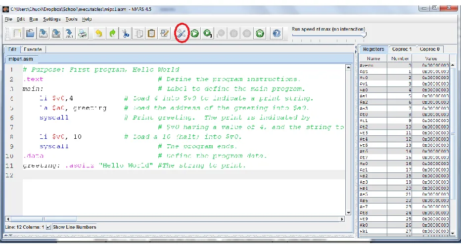
Figure 2-4: Assembling a program ... 43
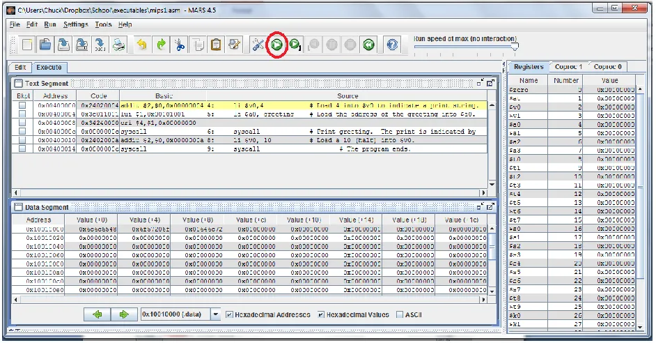
Figure 2-5: Running a program ... 44
Figure 2-6: Memory before entering a string ... 50
Figure 3-1: MIPS computer architecture ... 55
Figure 3-2: Assembled addition example ... 58
Figure 3-3: Addition Example after running 1 step. ... 59
Figure 4-1: R format instruction ... 83
Figure 4-2: I format instruction... 83
Figure 4-3: Machine Code example ... 84
Figure 4-4: Machine code for add $t0, $t1, $t2 ... 85
Figure 4-5: Machine code for sub $s0, $s1, $s2 ... 86
Figure 4-6: Machine code for addi $s2, $t8, 37 ... 86
Figure 4-7: Machine code for sll $t0, $t1, 10 ... 87
Figure 5-1: $pc when program execution starts ... 95
Figure 5-2: $pc after the execution of the first instruction ... 95
Figure 5-3: Just before calling PrintNewLine subprogram ... 96
Figure 5-4: Program has transferred control into the PrintNewLine subprogram ... 96
Figure 5-5: Subprogram calling semantics ... 97
Figure 5-6: Saving the $ra register ... 98
Figure 6-1: MIPS memory configuration ... 111
Figure 6-2: Static data memory allocation example ... 113
Figure 7-1: Instruction addresses for a simple program ... 141
Figure 7-2: Instruction addresses for program with pseudo operators ... 142
Figure 7-3: Branch offset program example ... 143
Figure 8-1: Push/Pop Example 1 ... 152
Figure 9-1: Heap memory example ... 166
Table of Tables
Table 1-1: Various names for binary values ... 15
Table 1-2: Values of 2n for n = 0...15 ... 16
Table 1-3: Names for values of 2n, n = 10, 20, 30, 40, 50, 60 ... 17
Table 1-4: Binary to Hexadecimal Conversion ... 19
Table 1-5: ASCII Table ... 21
Table 1-6: Truth table for NOT operator ... 29
Table 1-7: Truth table for AND, OR, NAND, NOR, and XOR ... 30
Table of Programs
Program 2-1: Hello World program ... 43
Program 2-2: Program to read an integer from the user ... 47
Program 2-3: Program to read a string from the user ... 48
Program 3-1: Addition Examples ... 58
Program 3-2: Even/odd number checking program ... 68
Program 3-3: Program to calculate 5*x^2 + 2*x + 3 ... 69
Program 3-4: Program to show order of operations matters ... 70
Program 3-5: Letter case conversion in assembly ... 74
Program 3-6: Program illustrating shift operations ... 79
Program 5-1: Implementing and calling Exit subprogram ... 91
Program 5-2: Implementing and calling the PrintNewLine subprogram... 93
Program 5-3: Input parameter with the PrintString subprogram ... 100
Program 5-4: Multiple input parameters with PrintInt subprogram ... 101
Program 5-5: File utils.asm ... 106
Program 5-6: Final program to prompt for, read, and print an integer ... 106
Program 6-1: Quadratic program pseudo code ... 116
Program 6-2: Accessing memory variables by label ... 117
Program 6-3: Register Direct Access ... 118
Program 6-4: Register Indirect Access ... 119
Program 6-5: Register offset access ... 120
Program 7-1: A simple program to show an if statement ... 126
Program 7-2: Assembly logic for ((x > 0) && ((x%2) == 0)) ... 127
Program 7-3: Assembly language logic for ((x > 0) && ((x%2) == 0) && (x < 10)) ... 127
Program 7-4: Assembly code fragement for an if-else statement ... 128
Program 7-5: if-else program example ... 129
Program 7-6: Program to implement if-elseif-else statement in assembly ... 131
Program 7-7: Sentinel control loop program ... 133
Program 7-8: Counter control loop program ... 135
Program 7-9: Program illustrating nested blocks... 137
Program 8-1: Stack class definition ... 151
Program 8-2: String class stack definition ... 153
Program 8-3: Recursive multiplication ... 161
Program 9-1: PromptString subprogram showing heap allocation ... 165
Program 9-2: AllocateArray subprogram ... 169
Program 9-3: Printing an array of integers ... 171
What you will learn
In this chapter you will learn:
1. binary numbers, and how they relate to computer hardware. 2. to convert to/from binary, decimal, and hexadecimal
3. binary character data representation in ASCII
4. integer numbers, which are represented in binary 2's complement format. 5. arithmetic operations for binary numbers
6. binary logic operations
7. the effect of context on data values in a computer.
Chapter 1
Introduction
One of the major goals of computer science is to use abstraction to insulate the users from how the computer works. For instance, computers can interpret speech and use natural language processing to allow novice users to perform some pretty amazing tasks. Even programming languages are written to enhance the ability of the person writing the code to create and support the program, and a goal of most modern languages is to be hardware agnostic.
Abstraction is a very positive goal, but at some level a computer is just a machine. While High Level Languages (HLL) abstract and hide the underlying hardware, they must be translated into assembly language to use the hardware. One of the goals of a computer science education is to strip away these abstraction and make the workings of the computing machine clear. Without an understanding of a computer as a machine, even the best programmer, system administrator, support staff, etc., will have significant gaps in what they are able to accomplish. A basic understanding of hardware is important to any computer professional.
Learning assembly language is different than learning a HLL. Assembly language is intended to directly manipulate the hardware that a program is run on. It does not rely on the ability to abstract behavior, instead giving the ability to specify exactly how the hardware is to work to the programmer. Therefore it uses a very different vocabulary than a HLL. That vocabulary is not composed of statements, variables and numbers but of operations, instructions, addresses, and bits.
In assembly it is important to remember that the actual hardware to be used only understands binary values 0 and 1. To begin studying assembly, the reader must understand the basics of binary and how it is used in assembly language programming. The chapter is written to help the reader with the concepts of binary numbers.
Chapter 1. 1
Binary Numbers
Chapter 1.1. 1
Values for Binary Numbers
might be fine for mathematics and logic, but is hopelessly inadequate for the engineering task of creating computer machines and languages.
To begin, the physical implementation of a binary value in a Central Processing Unit's (CPU) hardware, called a bit, is implemented as a circuit called a flip-flop or latch. A flip-flop has a voltage of either 0 volts or a positive voltage (most computers use +5 volts, but many modern computers use +3.3 volts, and any positive voltage is valid). If a flip-flop has a positive voltage it is called high or
on (true), and if it has 0 volts it is low or off (false). In addition hardware is made up of gates that which can either be open (true) or closed (false). Finally the goal of a computer is to be able to work with data that a person can understand. These numbers are always large, and hard to represent as a series of true or false values. When the values become large, people work best with numbers, so the binary number 0 is called false, and 1 is called true. Thus while computers work with binary, there are a number of ways we can talk about that binary. If the discussion is about memory, the value is
high, on, or 1. When the purpose is to describe a gate, it is open/closed. If there is a logical operations values can be true/false. The following table summarizes the binary value naming conventions.
T/F Number Switch Voltage Gate
F 0 Off Low Closed
T 1 On High Open
Table 1-1: Various names for binary values
In addition to the various names, engineers are more comfortable with real operators. This book will follow the convention that "+" is an OR operator, "*" is an AND operator, and "!"
(pronounced bang) is a not operator.
Some students are uncomfortable with the ambiguity in the names for true and false. They often feel that the way the binary values were presented in their mathematics classes (as true/false) is the "correct" way to represent them. But keep in mind that this class is about implementing a computer in hardware. There is no correct, or even more correct, way to discuss binary values. How they will be referred to will depend on the way in which the value is being used.
Understanding a computer requires the individual to be adaptable to all of these ways of referring to binary values. They will all be used in this text, though most of the time the binary values of 0 and 1 will be used.
Chapter 1.1. 2
Binary Whole Numbers
The numbering system that everyone learns in school is called decimal or base 10. This
numbering system is called decimal because it has 10 digits, [0..9]. Thus quantities up to 9 can be easily referenced in this system by a single number.
Computers use switches that can be either on (1) or off(0), and so computers use the binary, or base 2, numbering system. In binary, there are only two digits, 0 and 1. So values up to 1 can be easily represented by a single digit. Having only the ability to represent 0 or 1 items is too limiting to be useful. But then so are the 10 values which can be used in the decimal system. The question is how does the decimal handle the problem of numbers greater than 9, and can binary use the same idea?
When 99 is reached, we have 100, which is 1 group of hundred, 0 tens, and 0 ones. So the number 1,245 would be:
1,245 = 1*103 + 2*102 + 4*101+ 5*100
Base 2 can be handled in the same manner. The number 102 (base 2) is 1 group of two and 0 ones, or just 210 (base 10).1 Counting in base 2 is the same. To count in base 2, the numbers are 02, 12, 102, 112, 1002, 1012, 1102 1112, etc. Any number in base 2 can be converted to base 10 using this principal. Consider 1010112, which is:
1*25 + 0*24 + 1*23 + 0 *22 + 1*21 + 1*20 = 32 + 8 + 2 + 1 = 43 10
In order to work with base 2 number, it is necessary to know the value of the powers of 2. The following table gives the powers of 2 for the first 16 numbers (to 215). It is highly recommended that students memorize at least the first 11 values of this table (to 210), as these will be used frequently.
n 2n n 2n n 2n n 2n
0 1 4 16 8 256 12 4096
1 2 5 32 9 512 13 8192
2 4 6 64 10 1024 14 16348
3 8 7 126 11 2048 15 32768
Table 1-2: Values of 2n for n = 0...15
The first 11 powers of 2 are the most important because the values of 2n are named when n is a decimal number evenly dividable by 10. For example 210 is 1 Kilo, 220 is 1 Meg, etc. The names for these value of 2n are given in the following table. Using these names and the values of 2n from 0-9, it is possible to name all of the binary numbers easily as illustrated below. To find the value of 216, we would write:
216 = 210*26= 1K * 64 = 64K
Older programmers will recognize this as the limit to the segment size on older PC's which could only address 16 bits. Younger students will recognize the value of 232, which is:
232 = 230 * 22 = 1G * 4 = 4G
4M was the limit of memory available on more recent PC's with 32 bit addressing, though that limit has been moved with the advent of 64 bit computers. The names for the various values of 2n are given in the following table.
210 Kilo 230 Giga 250 Penta 220 Mega 240 Tera 260 Exa
Table 1-3: Names for values of 2n, n = 10, 20, 30, 40, 50, 60
Chapter 1. 2
Converting Binary, Decimal, and Hex Numbers
Chapter 1.2. 1
Converting Binary to Decimal
Computers think in 0's and 1's, and when dealing with the internal workings of a computer humans must adjust to the computers mindset. However when the computer produces answers, the humans that use them like to think in decimal. So it is often necessary for programmers to be able to convert between what the computer wants to see (binary), and what the human end users want to see (decimal). These next 3 sections will deal with how to convert binary to decimal, and then give 2 ways to convert decimal to binary. Finally it will give a section on a useful representation for handling large binary numbers called hexadecimal.
To convert binary to decimal, it is only necessary to remember that each 0 or 1 in a binary number represents the amount of that binary power of 2. For each binary power of 2, you have either 0 or 1 instance of that number. To see this, consider the binary number 10010102. This number has 1 * 26 + 0 * 25 + 0 * 24 + 1 * 23 + 0 * 22 + 1 * 21 + 0 * 20 = 64 + 8 + 2 = 7410. This can be generalized into an easy way to do this conversion. To convert from binary to decimal put the 2n value of each bit over the bits in the binary number and add the values which are 1, as in the example below:
64 32 16 8 4 2 1. ...
10010102 = 1 0 0 1 0 1 0 = 64 + 8 + 2 = 7410
Chapter 1.2. 2
Converting Decimal to Binary using Binary Powers
Two ways to convert decimal number to binary numbers are presented here. The first is easy to explain, but harder to implement. The second is a cleaner algorithm, but why the algorithm works is less intuitive.
The first way to convert a number from decimal to binary is to see if a power of 2 is present in the number. For example, consider the number 433. We know that there is no 29 (512) value in 433, but there is one value of 28 (or 256). So in the 9th digit of the base 2 number we would put a 1, and subtract that 256 from the value of 433.
433 - 256 = 177
Next check if there is a 27 (128) value in the number. There is, so add that bit to our string and subtract 128 from the result.
28 27 26 25 24 23 22 21 20
177 - 128 = 49
Now check for values of 26 (64). Since 64 > 49, put a zero in the 26 position and continue.
49 - 0 = 49
Continuing this process for 25 (32), 24(16), 23(8), 22(4), 21(2), and 20(1) results in the final answer.
Thus 43310 = 1101100012. This result can be checked by converting the base 2 number back to base 10.
Chapter 1.2. 3
Converting Decimal to Binary using Division
While conceptually easy to understand, the method to convert decimal numbers to binary numbers in Chapter 1.2.3 is not easy to implement as the starting and stopping conditions are hard to define. There is a way to implement the conversion which results in a nicer algorithm.
The second way to convert a decimal number to binary is to do successive divisions by the number 2. This is because if a number is divided and the remainder taken, the remainder is the value of the 20 bit. Likewise if the result of step 1 is divided again by 2 (so essentially dividing by 2*2 or 4), the reminder is the value of the 21 bit. This process is continued until the result of the division is 0. The example below shows how this works.
Start with the number 433. 433 divided by 2 is 216 with a remainder of 1. So in step 1 the result would have the first bit for the power of 2 set to one, as below:
433 / 2 = 216 r 1
28 27 26 25 24 23 22 21 20
1 1 - - - -
28 27 26 25 24 23 22 21 20
1 1 0 - - - -
28 27 26 25 24 23 22 21 20
1 1 0 1 1 0 0 0 1
28 27 26 25 24 23 22 21 20
The number 216 is now divided by 2 to give 108, and the remainder, zero, placed in the second bit.
216 / 2 = 108 r 0
The process continues to divide by 2, filling the remainder in each appropriate bit, until at last the result is 0, as below.
Chapter 1.2. 4
Converting between binary and hexadecimal
One of the biggest problems with binary is that the numbers rapidly become very hard to read. This is also true in decimal, where there is often a "," inserted between groupings of 103. So for example 1632134 is often written as 1,632,134, which is easier to read.
In binary, something similar is done. Most students are familiar with the term byte, which is 8 bits. But fewer know of a nybble, or 4 bits. 4 bits in binary can represent numbers between 0..15, or 16 values. So values of 4 bits are collected together and create a base 16 number, called a hexadecimal (or simply hex) number. To do this, 16 digits are needed, and arbitrarily the numbers and letters 0, 1, 2, 3, 4, 5, 6, 7, 8, 9, A, B, C, D, E, and F were chosen as the 16 digits. The binary numbers corresponding to these 16 digit hex numbers are given in the table below (note, the normal way to indicate a value is in hex is to write a 0x before it So decimal 10 would be 0xA).
Binary Number
Hex Digit
Binary Number
Hex Digit
Binary Number
Hex Digit
Binary Number
Hex Digit
0000 0x0 0001 0x 1 0010 0x 2 0011 0x 3
0100 0x 4 0101 0x 5 0110 0x 6 0111 0x 7
1000 0x 8 1001 0x 9 1010 0x A 1011 0x B
1100 0x C 1101 0x D 1110 0x E 1111 0x F
Table 1-4: Binary to Hexadecimal Conversion
28 27 26 25 24 23 22 21 20
- - - 0 1
28 27 26 25 24 23 22 21 20
The hex numbers can then be arranged in groups of 4 (or 32 bits) to make it easier to translate from a 32 bit computer.
Note that hex numbers are normally only used to represent groupings of 4 binary digits. Regardless of what the underlying binary values represent, hex will be used just to show what the binary digits are. So in this text all hex values will be unsigned whole numbers.
Most students recognize that a decimal number can be extended by adding a 0 to the left of a decimal number, which does not in any way change that number. For example 0043310 = 043310 = 43310. The same rule applies to binary. So the binary number 1101100012 = 0001101100012.
But why would anyone want to add extra zeros to the left of a number? Because to print out the hex representation of a binary number, I need 4 binary digits to do it. The binary number
1101100012 only has 1 binary digit in the high order byte. So to convert this number to binary it is necessary to pad it with left zeros, which have no effect on the number. Thus 1 10011 00012 = 0001 1011 00012= 0x1B1 in hex. Note that even the hex numbers are often paded with zeros, as the hex number 0x1B1 is normally be written 0x01B1, to get groupings of 4 hex numbers (or 32 bits).
It is often the case where specific bits of a 32 bit number need to be set. This is most easily done using a hex number. For instance, if a number is required where all of the bits except the right left most (or 1) bit of a number is set, you can write the number in binary as:
111111111111111111111111111111102
A second option is to write the decimal value as: 429496729510
Finally the hex value can be written as 0xFFFFFFFE
In almost all cases where specific bits are being set, a hex representation of the number is the easiest to understand and use.
Chapter 1. 3
Character Representation
All of the numbers used so far in this text have been binary whole numbers. While everything in a computer is binary, and can be represented as a binary value, binary whole numbers do not represent the universe of numbering systems that exists in computers. Two representations that will be covered in the next two sections are character data and integer data.
Though computers deal use binary to represent data, humans usually deal with information as symbolic alphabetic and numeric data. So to allow computers to handle user readable
alpha/numeric data, a system to encode characters as binary numbers was created. That system is called American Standard Code for Information Interchange (ASCII)2. In ASCII all character are represented by a number from 1 - 127, stored in 8 bits. The ASCII encodings are shown in the following table.
2 ASCII is limited to just 127 characters, and is thus too limited for many applications that deal with
Table 1-5: ASCII Table
Using this table, it is possible to encode a string such as "Once" in ASCII characters as the hexadecimal number 0x4F6E63653 (capital O = 0x4F, n = 0x6E, c = 0x53, e = 0x65 ).
Numbers as character data are also represented in ASCII. Note the number 13 is 0xD or 11012. However the value of the character string "13" is 0x3133. When dealing with data, it is
important to remember what the data represents. Character numbers are represented using binary values, but are very different from their binary numbers.
Finally, some of the interesting patterns in ASCII should be noted. All digits start with binary digits 0011 0000. Thus 0 is 0x0011 0000, 1 is 00011 0000, etc. To convert a numeric character digit to a number it is only necessary to subtract the character value of 0. For example, '0' - '0' = 0, '1' - '0' = 1, etc. This is the basis for an easy algorithm to convert numeric strings to numbers which will be discussed in the problems.
Also note that all ASCII upper case letters start with the binary string 0010 0000, and are 1 offset for each new character. So A is 0100 0001, B is 0100 0010, etc. Lower case letters start with the binary string 0110 and are offset by 1 for each new character, so a is 0110 0001, b is 0110 0010,
3 By now it is hoped that the reader is convinced that hexadecimal is a generally preferred way to represent data in a
etc. Therefore, all upper case letters differ from their lower case counterpart by a 1 in the digit 0100. This relationship between lower case and capital letters will be use to illustrate logical operations later in this chapter.
Chapter 1. 4
Adding Binary Whole Numbers
Before moving on to how integer values are stored and used in a computer for calculations, how to do addition of binary whole numbers needs to be covered.
When 2 one-bit binary numbers are added, the following results are possible: 02+02 = 02; 02+12 = 12; 12+02 = 12; and 12+12 = 102. This is just like decimal numbers. For example, 3+4=7, and the result is still one digit. A problem occurs, however, when adding two decimal numbers where the result is greater than the base of the number (for decimal, the base is 10). For example, 9+8. The result cannot be represented in one digit, so a carry digit is created. The result of 9+8 is 7 with a carry of 1. The carry of 1 is considered in the next digit, which is actually adding 3 digits (the two addends, and the carry). So 39 + 28 = 67, where the 10's digit (4) is the result of the two addends (3 and 2) and the carry (1).
The result of 12+12 = 102 in binary is analogous to the situation in base 10. The addition of 12+12 is 02 with a carry of 12, and there is a carry to the next digit of 12.
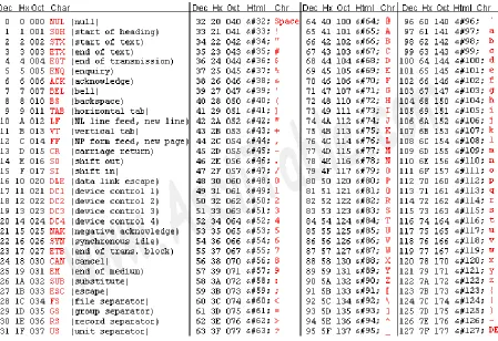
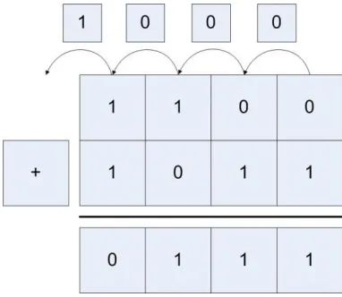
[image:24.612.237.377.367.487.2]An illustration of binary addition is shown in the figure below.
Figure 1-1: Binary whole number addition
Here the first bit adds 12 +12, which yields a 02 in this bit and a carry bit of 12. The next bit now has to add 12 +12 +12 (the extra one is the carry bit), which yields a 12 for this bit and a carry bit of 12. If you follow the arithmetic through, you have 00112 (310) + 01112 (710) = 10102 (1010).
Chapter 1. 5
Integer Numbers (2's Complement)
Chapter 1.5. 1
What is an Integer
When learning mathematics, negative numbers are represented using a sign magnitude format, where a number has a sign (positive or negative), and a magnitude (or value). For example -3 is 3 units (it's magnitude) away from zero in the negative direction (it's sign). Likewise, +5 is 5 units away from zero in a positive direction. Signed magnitude numbers are used in computers, but not for integer values. For now, just realize that it is excessively complex to do arithmetic using signed magnitude numbers. There is a much simpler way to do things called 2's
complement. This text will use the term integer and 2's complement number interchangeably.
Chapter 1.5. 2
2's complement operation and 2's complement format
Many students get confused and somehow believe that a 2's complement has something to do with negative numbers, so this section will try to be as explicit here as possible. Realize that if someone asks, "What is a 2's complement?", they are actually asking two very different
questions. There is a 2's complement operation which can be used to negate a number (e.g. translate 2 -> -2 or -5 -> 5). There is also a 2's complement representation (or format) of
numbers which can be used to represent integers, and those integers can be positive and negative whole numbers.
To reiterate, the 2's complement operation can convert negative numbers to the corresponding positive values, or positive numbers to the corresponding negative values. The 2's complement operation negates the existing number, making positive numbers negative and negative numbers positive.
A 2's complement representation (or format) simply represents number, either positive or negative. If you are ever asked if a 2's complement number is positive or negative, the only appropriate answer is yes, a 2's complement number can be positive or negative.
The following sections will explain how to do a 2's complement operation, and how to use 2's complement numbers. Being careful to understand the difference between a 2's complement operation and 2's complement number will be a big help to the reader.
Chapter 1.5. 3
The 2's Complement Operation
A 2's complement operation is simply a way to calculate the negation of a 2's complement
number. It is important to realize that creating a 2's complement operation (or negation) is not as simple as putting a minus sign in front of the number. A 2's complement operation requires two steps: 1 - Inverting all of the bits in the number; and 2 - Adding 12 to the number.
Consider the number 001011002. The first step is to reverse all of the bits in the number (which will be achieved with a bit-wise ! operation. Note that the ! operator is a unary operation, it only takes one argument, not two.
! (001011002) = 110100112
Note that in the equation above the bits in the number have simply been reversed, with 0's becoming 1's, and 1's becoming 0's. This is also called a 1's complement, though in this text we will never use a 1's complement number.
110100112 000000012 110101002.
Thus the result of a 2's complement operation on 001011002 is110101002 , or negative 2's complement value. This process is reversible, as the reader can easily show that the 2's complement value of 110101002 is001011002. Also note that both the negative and positive values are in 2's complement representation.
While positive numbers will begin with a 0 in the left most position, and negative numbers will begin with a 1 in the leftmost position, these are not just sign bits in the same sense as the signed magnitude number, but part of the representation of the number. To understand this difference, consider the case where the positive and negative numbers used above are to be represented in 16 bits, not 8 bits. The first number, which is positive, will extend the sign of the number, which is 0. As we all know, adding 0's to the left of a positive number does not change the number. So 001011002 would become 00000000001011002.
However, the negative value cannot extend 0 to the left. If for no other reason, this results in a 0 in the sign bit, and the negative number has been made positive. So to extend the negative number 110101002 to 16 bits requires that the sign bit, in this case 1, be extended. Thus 110101002 becomes 11111111110101002.
The left most (or high) bit in the number is normally referred to as a sign bit, a convention this text will continue. But it is important to remember it is not a single bit that determines the sign of the number, but a part of the 2's complement representation.
Chapter 1.5. 4
The 2's Complement (or Integer) Type
Because the 2's complement operation negates a number, many people believe that a 2's
complement number is negative. A better way to think about a 2's complement number is that is a type. A type is an abstraction which has a range of values, and a set of operations. For a 2's complement type, the range of values is all positive and negative whole numbers. For
operations, it has the normal arithmetic operations such as addition (+), subtraction (-), multiplication (*) , and division (/).
A type also needs an internal representation. In mathematics classes, numbers were always abstract, theoretical entities, and assumed to be infinite. But a computer is not an abstract entity, it is a physical implementation of a computing machine. Therefore, all numbers in a computer must have a physical size for their internal representation. For integers, this size is often 8 (byte), 16(short), 32(integer), or 64(long) bits, though larger numbers of bits can be used to store the numbers. Because the left most bit must be a 0 for positive, and 1 for negative, using a fixed size also helps to identify easily if the number is positive or negative.
Finally, as stated in the previous section, just like zeros can be added to the left of a positive number without effecting its value, in 2's complement ones can be added to the left of a negative number without effecting its value. For example:
00102 = 0000 00102 = 210
11102 = 1111 1110 2= -210
Adding leading zeros to a positive number, and leading ones to a negative number, is called sign extension of a 2's complement number.
Chapter 1. 6
Integer Arithmetic
Chapter 1.6. 1
Integer Addition
[image:27.612.227.387.313.450.2]Binary whole number addition was covered in chapter 1.4. Integer addition is similar to binary whole number addition except that both positive and negative numbers must be considered. For example, consider adding the two positive numbers 00102 (210) + 00112 (310) = 01012 (510).
Figure 1-2: Addition of two positive integers
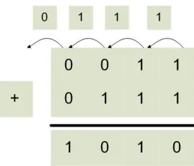
Addition of mixed positive and negative numbers, and two negative numbers also works in the same manner, as the following two examples show. The first adds 00102 (210) + 11012 (-310) = 11112 (-110), and the second adds 11102 (-210) + 11012 (-310) = 10112 (-510).
[image:27.612.232.381.527.660.2]Figure 1-4: Addition of two negative integers
Because integers have fixed sizes, addition and subtraction can cause a problem known as integer overflow. This happens which the two numbers which are being added are large positive or negative values, and the combining of the values results in numbers too big to be store in the integer.
Chapter 1.6. 2
Overflow of Integer Addition
Because integers have fixed sizes, addition and subtraction can cause a problem known as integer overflow. This happens which the two numbers which are being added are large positive or negative values, and the combining of the values results in numbers too big to be store in the integer value.
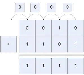
For example, a 4 bit integer can store values from -8...7. So when 01002 (410) + 01012 (5) = 10012 (-7) are added using 4 bit integers the result is too large to store in the integer. When this happens, the number changes sign and gives the wrong answer, as the following figure shows.
Figure 1-5: Addition with overflow
Attempting to algorithmically figure out if overflow occur is difficult. First if one number is positive and the other is negative, overflow never occurs. If both numbers are positive or
[image:28.612.221.394.450.604.2]There is a much easier way to figure out if overflow has occurred. If the carry in bit to the last digit is the same as the carry out bit, then no overflow has occurred. If they are different, then overflow has occurred. In figure 1.3 the carry in and carry out for the last bit are both 0, so there is no overflow. Likewise, in figure 1.4 the carry in and carry out are both 1, so there was no overflow. In figure 1.5 the carry in is 1 and the carry out is 0, so overflow has occurred.
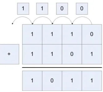
[image:29.612.210.401.202.368.2]This method also works for addition of negative numbers. Consider adding 11002 (-410) and 10112 (-510) = 01112 (710), shown in figure 1.6. Here the carry in is 0 and the carry out is 1, so once again overflow has occurred.
Figure 1-6: Subtraction with overflow
Chapter 1.6. 3
Integer multiplication using bit shift operations
Multiplication and division of data values or variables involves hardware components in the Arithmetic Logic Unit (ALU). In assembly these operations will be provided by the various forms mul and div operators, and the hardware to implement them is beyond the scope of this book and will not be covered. However, what is of interest in writing assembly is multiplication and division by a constant.
The reason multiplication and division by a constant is covered is that these operations can be provided by bit shift operations, and the bit shift operations are often faster to run than the equivalent mul or div operation. Therefore, bit shift operations are often used in assembly to do multiplication and division, and therefore it is important for assembly language programmers to understand how this works.
First consider multiplication of a number by a power of 10 in base 10. In base 10, if a number is multiplied by a power of 10 (10n, where n is the power of 10), it is sufficient to move the number n places to the right filling in with 0's. For example, 15*1000 (or 15 * 103) = 15,000.
(000011112<<3), yielding 011110002, or 120. So it is easy to multiply any number represented in base 2 by a power of 2 (for example 2n) by doing n left bit shifts and backfilling with 0's.
Note that this also works for multiplication of negative 2's complement (or integer) numbers. Multiplying 111100012 (-15) by 2 is done by moving the bits left 1 space and again appending a 0, yielding 111000102 (or -30) (note that in this case 0 is used for positive or negative numbers). Again multiply 111100012 (-15) by 8 is done using 3 bit shifts and backfilling the number again with zeros, yielding 100010002 (-120)
By applying simple arithmetic, it is easy to see how to do multiplication by a constant 10. Multiplication by 10 can be thought of as multiplication by (8+2), so (n*10) = ((n*8)+(n*2)).
15*10 = 15 * (8+2) = 15 *8 + 15 * 2 = (000011112 << 3) + (000011112 << 1) =
11110002 + 111102 = 1001001102 = 150
This factoring procedure applies for multiplication by any constant, as any constant can be represented by adding powers of 2. Thus any constant multiplication can be encoded in
assembly as a series of shifts and adds. This is sometimes faster, and often easier, than doing the math operations, and should be something every assembly language programmer should be familiar with.
This explanation of the constant multiplication trick works in assembly, which begs the question does it also work in a HLL? The answer is yes and no. Bit shifts and addition can be done in most programming languages, so constant multiplication can be implemented as bits shifts and addition. But because it can be done does not mean it should be done. In HLL (C/C++, Java, C#, etc.) this type of code is arcane, and difficult to read and understand. In addition, any decent compiler will convert constant multiplication into the correct underlying bit shifts and additions when it is more efficient to do so. And the compiler will make better decisions about when to use this method of multiplication, and implement it more effectively and with fewer errors than if a programmer were to do it. So unless there is some really good reason to do multiplication using bit shifts and addition, it should be avoided in a HLL.
Chapter 1.6. 4
Integer division using bit shift operations
Since multiplication can be implemented using bit shift operations, the obvious question is whether or not the same principal applies to division? The answer is that for some useful cases, division using bit shift operations does work. But in general, it is full of problems.
The cases where division using bit shift operations works are when the dividend is positive, and the divisor is a power of 2. For example, 000110012 (25) divided by 2 would be a 1-bit shift, or 000011002 (12). The answer 12.5 is truncated, as this is easily implemented by throwing away the bit which has been shifted out. Likewise,00 0110012 (25) divided by 2 is 000000112 (3), with truncation again occurring. Note also that in this case the bit that is shifted in is the sign bit, which is necessary to maintain the correct sign of the number.
This leaves two issues. The first is why can this method not be implemented with constants other than the powers of 2. The reason is that division is only distributive in one direction over addition, and in our case it is the wrong direction. Consider the equation 60/10. It is easy to show that division over addition does not work in this case.
60/10 = 60/(8+2) ≠ 60/8 + 60/2
The second issue is why the dividend must be positive. To see why this is true, consider the following division, -15 / 2. This result in the following:
111110012 >> 1 = 11111100 = -8
Two things about this answer. First in this case the sign bit, 1, must be shifted in to maintain the sign of the integer.
Second in this case the lowest bit, a 1, is truncated. This means that -7.5 is truncated down to -8. However, many programmers believe that -7.5 should truncate to -7. Whether the correct answer is -7 or -8 is debatable, and different programming languages have implemented as either value (for example, Java implements -15/2 = -7, but Python -15/2 as -8). This same problem occurs with many operations on negative numbers, such a modulus. And while such debates might be fun, and programmers should realize that these issues can occur, it is not the purpose of this book to do more than present the problem.
Chapter 1. 7
Boolean Logical and Bitwise Operators
Chapter 1.7. 1
Boolean Operators
Boolean operators are operators which are designed to operate on a Boolean or binary data. They take in one or more input values of 0/14 and combine those bits to create an output value which is either 0/1. This text will only deal with the most common Boolean operators, the unary operator NOT (or inverse), and the binary operators5 AND, OR, NAND, NOR, and XOR. These operators are usually characterized by their truth tables, and two truth tables are given below for these operators.
A NOT
0 1
1 0
Table 1-6: Truth table for NOT operator
4 Note that the values 0/1 are used here rather than F/T. These operators will be described through the rest of the
book using the binary values 0/1, so there is no reason to be inconsistent here.
5 The term unary operator means having one input. The term binary operator means having two inputs. Be careful
Input Output
A B AND OR NAND NOR XOR
0 0 0 0 1 1 0
0 1 0 1 1 0 1
1 0 0 1 1 0 1
1 1 1 1 0 0 0
Table 1-7: Truth table for AND, OR, NAND, NOR, and XOR
Chapter 1.7. 2
Logical and Bitwise Boolean Operators
There are two kinds of Boolean operators implemented in many programming languages. They are logical operators and bitwise operators. Logical operators perform Boolean operations to obtain a single value at the end. For example, in Java a programmer might write:
if ((x != 0) && (y / x > 4))
The purpose of this statement is to decide whether or not to enter the statement or code block associated with the if test. What is desired is a single answer, or a single bit, which is either true (1) or false (0). This has two consequences. The first is that in some programming languages (e.g. C/C++) a variable other than a Boolean can be used in the statement, with the consequence that 0 is false, and anything but 0 is true. For example, in the statement if(x=64), the result is true. The equal operator returns a non-zero value, 64, which is true. This has been the cause of many bugs in C/C++, and most modern compilers at least complain about this. This will also be the result of some expressions in assembler, and there will be no compiler to complain about it. So be careful.
The second consequence of the logical Boolean operator is that once a part of it has failed, the entire statement has to fail, and so the rest of the statement will not be executed. This is called short circuiting, and all logical operators are thus short circuiting operators. To see why this is true, consider the if test about. In this if test, if x is 0, then (x != 0) is false. Since false and anything is false, there is no need to evaluate the second part of this equation, and so the statement (y / x > 4) is not executed. Many programmers will recognize this code, as it is a common pattern for protecting against a zero divide.
The important take away from this is that logical operators are short circuiting operators.
On the other hand, bit-wise operators are not short circuiting. Consider the following problem. A programmer wants to write a toLower method which will convert an upper case letter to a lower case letter. In chapter 1.3 it was pointed out that the difference between an upper case letter and a lower case letter is that in a lower case letter the bit 0x20 (001000002) is 1, whereas in the upper case letter it is zero. So to convert from upper case letter to letter case, it is only necessary to OR the upper case letter with 0x20. In pseudo code this could be implemented as follows:
In this case the OR operator, |, needs to operator on every bit in the variables. Therefore, the | operator is not short circuiting, it will process every bit regardless of whether or not a previous bit would cause the operation to fail.
It is possible to use bitwise operators in place of logical operators, but it is usually incorrect to do so. For example, in the previous if statement, if a bitwise operator had been used no short
circuiting would have occurred and the zero divide could occur.
if ((x != 0) & (y / x > 4))
Many languages such as C/C++, Java, C#, etc, have both logical (short circuiting) and bitwise operators. In most cases the single character operator is a bit wise operator (e.g. &, |, etc.) and the double character operator is the logical operator (&&, ||, etc.).
To make things more confusing, in MIPS only non-short circuiting operators are used, however they are often called logical operators. There is no good way to reconcile this, so the user is cautioned to read the material and programs carefully.
Chapter 1. 8
Context
The final bit of information to take from this chapter is that data in a computer is a series of "1" or "0" bits. In computer memory two bytes containing “01000001” could exists. The question is what does this byte mean? Is the byte an integer number corresponding to decimal 65? Is this an ASCII character, representing the letter "A". Is it a floating point number, or maybe an address? The answer is you have no idea!
To understand data there has to be a context. HLL alway provide the context with the data (for example, the type, as in int a;), so the programmer does not have to worry about it. However, in assembly the only context is the one the programmer maintains, and it is external to the program. Is it possible to convert an integer number from upper case to lower case? Or to add two
operations? The answer is yes, anything is possible in assembly, but that does not mean it makes sense to do it.
In assembly language it is important for the programmer to always be aware of what a series of bits in memory represents, or the context of the data. Remember that data without a context is never meaningful.
Chapter 1. 9
Summary
In this chapter the concept of binary was introduced, as well as ways to represent binary data such as binary whole numbers, integers, and ASCII. Arithmetic and logical operations were defined for binary data. Finally, the chapter introduced the concept of a context, where the context defines the meaning of any binary data.
Chapter 1. 10
Exercises
1) What are the following numbers in binary and hexadecimal? a. 1310
c. 2510 d. 15710 e. 32510 f. 109610
2) What are the following numbers in decimal?
a. 100111002
b. 9C16 c. 1F16 d. 0C16 e. 109A16
3) Give the value of the following numbers (IE. 232 = 4G) a. 216
b. 224 c. 229 d. 234 e. 231
4) Give the 2’s complement form for each of the following numbers:
a. 13
b. -13
c. 156
d. -209
5) Do the following calculations using 2’s complement arithmetic. Show whether there is an overflow condition or not. CHECK YOUR ANSWERS!
a. 13 + 8 with 5 bits precision b. 13 + 8 with 6 bits precision c. 13 – 8 with 5 bits precision d. 13 – 8 with 6 bits precision e. -13 – 8 with 5 bits precision f. -13 – 8 with 6 bits precision g. 105 – 57 with 8 bits precision
6) Do the following multiplication operations using binary shift operations. Check your answers.
a. 5 * 4
b. 13 * 12
c. 7 * 10 d. 15 * 5
7) What is the hex representation of the following numbers (note that they are strings):
a. “52”
8) Perform the following multiplication and division operations using only bit shifts. a. 12 * 4
b. 8 * 16
c. 12 * 10
d. 7 * 15 e. 12 / 8 f. 64 / 16
9) Explain the difference between a short circuiting and non short circuiting logical expression. Why do you think these both exist?
10)In your own words, explain why the context of data found in a computer is important. What provides the context for data?
11)Convert the following ASCII characters from upper case to lower case. Do not refer to the ASCII table.
a. 0x41 (character A) b. 0x47 (character G)
c. 0x57 (character W)
12)Convert the following ASCII characters from lower case to upper case. Do not refer to the ASCII table.
a. 0x 62 (character b) b. 0x69 (character i) c. 0x6e (character n)
13)Write the functions toUpper and toLower in the HLL of your choice (C/C++, Java, C#, etc.) The toUpper function converts the input parameter string so that all characters are uppercase. The toLower function converts the input parameter string so that all characters are lowercase. Note that the input parameter string to both functions can contain both upper and lower case letters, so you should not attempt to do this using addition.
14)Implement a program in the HLL of your choice that converts an ASCII string of characters to an integer value. You must use the follow pseducode algorithm:
read numberString outputNumber = 0
while (moreCharacters) { c = getNextCharacter num = c - '0';
outputNumber = outputNumber * 10 + num; }
print outputNumber;
16)Write a program in the HLL of your choice to take an integer and write its value out in hex. You cannot use string formatting characters.
17)Is bit shift by 1 bit the same as division by 2 for negative integer numbers? Why or why not?
18)Can multiplication of two variables (not constants) be implemented using the bit shift operations covered in this chapter? Would you consider using the bit shift operations implementation of multiplication and divide for two variables, or would you always use the mul or div operators in MIPS assembly? Defend your choice.
19)Should you use bit shift operations to implement multiplication or division by a constant in a HLL? What about assembly makes it more appropriate to use these operations?
20)What does the Unix strings command do? How does the command attempt to provide a
What you will learn
In this chapter you will learn:
1. to download, install, and run the MARS IDE.
2. what are registers, and how are they used in the CPU. 3. register conventions for MIPS.
4. how memory is configured for MIPS.
5. to assemble and run a program in MARS.
6. the syscall instruction, and how to pass parameters to syscall. 7. what immediate values are in assembly language.
8. assembler directives, operators, and instructions.
9. to input and output integer and string data in MIPS assembly.
Chapter 2
First Programs in MIPS assembly
This chapter will cover first program that is often implemented when writing in a new language, a Hello World program. This program is significant in any language because it covers the most fundamental concepts any program can achieve, creating an executing program that can read data in and print results out. Creating an executing program is important because it covers an
Integrated Development Environment (IDE) which will allow the programmer to edit the program and to create resultant execution of that program. Being able to input data and output results covers a basic understanding of registers, I/O mechanisms, and provides a mechanism to test algorithms by allowing users to enter data and see if the result is what is expected.
This first program is particularly important because the concepts of statements and variables require a much more in depth knowledge of the language and platform. This chapter is intended to prepare the reader for the rigors of programming MIPS assembly by leading the reader step-by-step into a first working program.
Chapter 2. 1
The MARS IDE
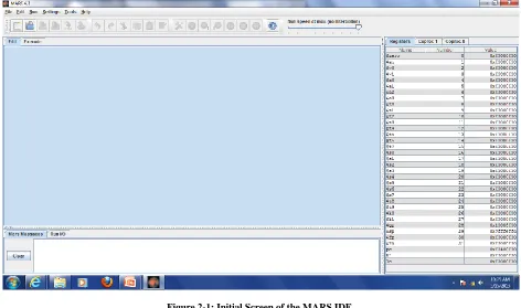
This text will use an IDE called the MIPS Assembler and Runtime Simulator (MARS). There are a number of MIPS simulators available, some for educational use, and some for commercial use. However in the opinion of this author, MARS is the easiest to use, and provides the best tools for explaining how MIPS assembly and the MIPS CUP work.
MARS was written by Pete Sanderson and Kenneth Vollmar, and is documented at the site
http://courses.missouristate.edu/kenvollmar/mars/index.htm, and should be downloaded from this site. MARS is an executable jar file, so you must have the Java Runtime Environment (JRE) installed to run MARS. A link to Java is on the MARS download page, so you should install Java if it is not on your computer.
Figure 2-1: Initial Screen of the MARS IDE
Chapter 2. 2
MIPS and memory
(Note: the next two sections provide background material to assist the reader in understanding the MIPS programs later in the chapter. It might be helpful to first read lightly through this material, then implement the programs. This material is difficult to understand, even for some experienced programmers. It is anticipated that the reader will have to refer to this section throughout the reading of the rest of the book, and quite possibly for future reference in programming in other languages. How memory is implemented and used is a complex and interesting topic, so at least some level of understanding is foundational for the study of Computer Science. ) .
It is not unusual for novice programmers to have no concept of memory except as a place to store variables. For a novice this is sufficient, but any real program will require that a programmer have at least a basic knowledge of the types of memory that are used, and the characteristics of each. For example programs that use concurrency are difficult to implement without problems if memory is not understood. Some very powerful design patterns, such as an Immutable Objects, Singletons, or a State Pattern, cannot be understood properly without a knowledge of the
characteristics of different types of memory. So every programmer should have at least a basic understanding of how the different types of memory that are used in nearly every computer platform.
Chapter 2.2. 1
Types of memory
To a programmer, memory in MIPS is divided into two main categories. The first category, memory that exists in the Central Processing Unit (CPU) itself, is called register memory or more commonly simply registers. Register memory is very limited and contained in what is often called a register file on the CPU. This type of memory will be called registers in this text.
The second type of memory is what most novice programmers think of as memory, and is often just called memory. Memory for the purposes of this book is where a HLL programmer puts instructions and data. HLL programmers have no access to registers, and so generally have no knowledge of their existence. So from a HLL programmer's point of view, anything stored on a computer is stored in memory.
The non-register memory space of a modern computer, is divided into many different categories, each category having different uses. The different areas of memory studied in detail in this text will be the text, static data, heap and stack sections. Other areas also exist, though this text will not cover them.
Caveats about memory
Students are always complaining that in Computer Science the same terms refer to different things. For example, a binary heap and heap memory are both heaps, but they are completely unrelated terms. As with any study of a complex organization, definitional problems will exist in the study of memory. Therefore it is important to be flexible and understand the contextual meaning or a term and not simply the words. Also keep in mind that external sources of information, like the WWW, may use different terminology, or even the same words with different meanings. So when researching memory, keep the following points in mind.
The first thing to keep in mind is that the view of memory in this text is the programmers view of the memory. The actual implementation of the memory is likely to include virtual memory and several layers of cache. All of this will be hidden from the programmer, so the complexities of the implementation of memory are not considered in this book.
The second thing to keep in mind is that this text will present an older model of memory which is a single threaded process, and does not have virtual program execution (such as the Java Virtual Machine). In reality memory can and does become much more complex than the model given here, but this model is already complex enough, and meets the needs of our assembler programs. So it is a good place to begin understanding memory.
Chapter 2.2. 2
Overview of a MIPS CPU
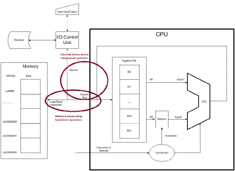
Figure 2-2: 3-address store/load computer architecture
All CPU architectures contain 3 main units. The first is the ALU, which performs all
calculations such as addition, multiplication, subtraction, division, bit-shifts, logical operations, etc. Except for instructions which interface to units not on the CPU, such as memory access or interactions with the user of disks, all operations use the ALU. In fact it is reasonable to view basic purpose of the CPU as doing some sort of ALU operation on values from two registers, and storing the result back into a third register.
This interaction of the registers and the CPU helps to explain the purpose of the registers. Registers are a limited amount of memory which exists on the CPU. No data can be operated on in the CPU that is not stored in a register. Data from memory, the user, or disk drives must first be loaded into a register before the CPU can use it. In the MIPS CPU, there are only 32
registers, each of which can be used to store a single 32 bit values. Because the number of these registers is so limited, it is vital that the programmer use them effectively.
In order to use data from memory, the address and data to be read/written is placed on the system b