Direct Energy Conversion by Andrea M. Mitofsky is licensed under the Cre-ative Commons Attribution-NonCommercial 4.0 International License. To view a copy of this license, visit http://creativecommons.org/licenses/ by-nc/4.0/.
This is version 1.0.0 of the text.
The copyright license does not apply to the following gures: Fig. 2.10, Fig. 6.6, Fig. 6.14, Fig. 6.15, Fig. 6.17, Fig. 7.1, Fig. 7.3, Fig. 7.7, Fig. 7.8, Fig. 8.4, Fig. 8.5, Fig. 8.6, Fig. 9.8, and Fig. 9.10. These gures are used, with permission from other authors. The caption for each gure cites the source.
This textbook can be cited as:
A. M. Mitofsky, Direct Energy Conversion, 2018.
This textbook can be downloaded from:
https://www.trine.edu/books/directenergy.aspx/
Contents
Contents i
1 Introduction 1
1.1 What is Direct Energy Conversion? . . . 1
1.2 Preview of Topics . . . 2
1.3 Conservation of Energy . . . 9
1.4 Measures of Power and Energy . . . 10
1.5 Properties of Materials . . . 12
1.5.1 Macroscopic Properties . . . 12
1.5.2 Microscopic Properties . . . 13
1.6 Electromagnetic Waves . . . 15
1.6.1 Maxwell's Equations . . . 15
1.6.2 Electromagnetic Waves in Free Space . . . 17
1.6.3 Electromagnetic Waves in Materials . . . 18
1.7 Problems . . . 21
I Survey of Energy Conversion Devices
23
2 Capacitors and Piezoelectric Devices 23 2.1 Introduction . . . 232.2 Capacitors . . . 24
2.2.1 Material Polarization . . . 24
2.2.2 Energy Storage in Capacitors . . . 24
2.2.3 Permittivity and Related Measures . . . 26
2.2.4 Capacitor Properties . . . 28
2.3 Piezoelectric Devices . . . 31
2.3.1 Piezoelectric Strain Constant . . . 32
2.3.2 Piezoelectricity in Crystalline Materials . . . 33
2.3.3 Piezoelectricity in Amorphous and Polycrystalline Ma-terials and Ferroelectricity . . . 41
2.3.4 Materials Used to Make Piezoelectric Devices . . . . 43
2.3.5 Applications of Piezoelectricity . . . 44
2.4 Problems . . . 47
3 Pyroelectrics and Electro-Optics 53 3.1 Introduction . . . 53
3.2 Pyroelectricity . . . 53
3.2.2 Pyroelectricity in Amorphous and Polycrystalline
Ma-terials and Ferroelectricity . . . 55
3.2.3 Materials and Applications of Pyroelectric Devices . 55 3.3 Electro-Optics . . . 56
3.3.1 Electro-Optic Coecients . . . 56
3.3.2 Electro-Optic Eect in Crystalline Materials . . . 59
3.3.3 Electro-Optic Eect in Amorphous and Polycrystalline Materials . . . 60
3.3.4 Applications of Electro-Optics . . . 60
3.4 Notation Quagmire . . . 61
3.5 Problems . . . 64
4 Antennas 67 4.1 Introduction . . . 67
4.2 Electromagnetic Radiation . . . 69
4.2.1 Superposition . . . 69
4.2.2 Reciprocity . . . 69
4.2.3 Near Field and Far Field . . . 72
4.2.4 Environmental Eects on Antennas . . . 72
4.3 Antenna Components and Denitions . . . 73
4.4 Antenna Characteristics . . . 75
4.4.1 Frequency and Bandwidth . . . 75
4.4.2 Impedance . . . 77
4.4.3 Directivity . . . 78
4.4.4 Electromagnetic Polarization . . . 82
4.4.5 Other Antenna Considerations . . . 85
4.5 Problems . . . 86
5 Hall Eect 91 5.1 Introduction . . . 91
5.2 Physics of the Hall Eect . . . 91
5.3 Magnetohydrodynamics . . . 96
5.4 Quantum Hall Eect . . . 97
5.5 Applications of Hall Eect Devices . . . 98
5.6 Problems . . . 100
6 Photovoltaics 101 6.1 Introduction . . . 101
6.2 The Wave and Particle Natures of Light . . . 101
6.3 Semiconductors and Energy Level Diagrams . . . 104
6.3.2 Energy Levels in Isolated Atoms and in Semiconductors106 6.3.3 Denitions of Conductors, Dielectrics, and
Semicon-ductors . . . 114
6.3.4 Why Are Solar Cells and Photodetectors Made from Semiconductors? . . . 115
6.3.5 Electron Energy Distribution . . . 117
6.4 Crystallography Revisited . . . 119
6.4.1 Real Space and Reciprocal Space . . . 119
6.4.2 E versus k Diagrams . . . 120
6.5 Pn Junctions . . . 122
6.6 Solar Cells . . . 127
6.6.1 Solar Cell Eciency . . . 127
6.6.2 Solar Cell Technologies . . . 129
6.6.3 Solar Cell Systems . . . 130
6.7 Photodetectors . . . 132
6.7.1 Types of Photodetectors . . . 132
6.7.2 Measures of Photodetectors . . . 134
6.8 Problems . . . 136
7 Lamps, LEDs, and Lasers 139 7.1 Introduction . . . 139
7.2 Absorption, Spontaneous Emission, Stimulated Emission . . 139
7.2.1 Absorption . . . 139
7.2.2 Spontaneous Emission . . . 140
7.2.3 Stimulated Emission . . . 142
7.2.4 Rate Equations and Einstein Coecients . . . 143
7.3 Devices Involving Spontaneous Emission . . . 147
7.3.1 Incandescent Lamps . . . 147
7.3.2 Gas Discharge Lamps . . . 148
7.3.3 LEDs . . . 150
7.4 Devices Involving Stimulated Emission . . . 152
7.4.1 Introduction . . . 152
7.4.2 Laser Components . . . 153
7.4.3 Laser Eciency . . . 157
7.4.4 Laser Bandwidth . . . 159
7.4.5 Laser Types . . . 161
7.4.6 Optical Ampliers . . . 165
7.5 Relationship Between Devices . . . 165
8 Thermoelectrics 173
8.1 Introduction . . . 173
8.2 Thermodynamic Properties . . . 173
8.3 Bulk Modulus and Related Measures . . . 176
8.4 Ideal Gas Law . . . 178
8.5 First Law of Thermodynamics . . . 179
8.6 Thermoelectric Eects . . . 180
8.6.1 Three Related Eects . . . 180
8.6.2 Electrical Conductivity . . . 183
8.6.3 Thermal Conductivity . . . 184
8.6.4 Figure of Merit . . . 186
8.7 Thermoelectric Eciency . . . 188
8.7.1 Carnot Eciency . . . 188
8.7.2 Other Factors That Aect Eciency . . . 191
8.8 Applications of Thermoelectrics . . . 192
8.9 Problems . . . 195
9 Batteries and Fuel Cells 201 9.1 Introduction . . . 201
9.2 Measures of the Ability of Charges to Flow . . . 202
9.2.1 Electrical Conductivity, Fermi Energy Level, and En-ergy Gap Revisited . . . 203
9.2.2 Mulliken Electronegativity . . . 204
9.2.3 Chemical Potential and Electronegativity . . . 205
9.2.4 Chemical Hardness . . . 207
9.2.5 Redox Potential . . . 207
9.2.6 pH . . . 208
9.3 Charge Flow in Batteries and Fuel Cells . . . 211
9.3.1 Battery Components . . . 211
9.3.2 Charge Flow in a Discharging Battery . . . 212
9.3.3 Charge Flow in a Charging Battery . . . 213
9.3.4 Charge Flow in Fuel Cells . . . 214
9.4 Measures of Batteries and Fuel Cells . . . 216
9.4.1 Cell Voltage, Specic Energy, and Related Measures 216 9.4.2 Practical Voltage and Eciency . . . 219
9.5 Battery Types . . . 223
9.5.1 Battery Variety . . . 223
9.5.2 Lead Acid . . . 225
9.5.3 Alkaline . . . 226
9.5.4 Nickel Metal Hydride . . . 227
9.6 Fuel Cells . . . 229
9.6.1 Components of Fuel Cells and Fuel Cell Systems . . . 229
9.6.2 Types and Examples . . . 231
9.6.3 Practical Considerations of Fuel Cells . . . 232
9.7 Problems . . . 234
10 Miscellaneous Energy Conversion Devices 237 10.1 Introduction . . . 237
10.2 Thermionic Devices . . . 237
10.3 Radiation Detectors . . . 237
10.4 Biological Energy Conversion . . . 239
10.5 Resistive Sensors . . . 239
10.6 Electrouidics . . . 241
II Theoretical Ideas
245
11 Calculus of Variations 245 11.1 Introduction . . . 24511.2 Lagrangian and Hamiltonian . . . 245
11.3 Principle of Least Action . . . 247
11.4 Derivation of the Euler-Lagrange Equation . . . 249
11.5 Mass Spring Example . . . 251
11.6 Capacitor Inductor Example . . . 258
11.7 Schrödinger's Equation . . . 262
11.8 Problems . . . 263
12 Relating Energy Conversion Processes 269 12.1 Introduction . . . 269
12.2 Electrical Energy Conversion . . . 270
12.3 Mechanical Energy Conversion . . . 276
12.4 Thermodynamic Energy Conversion . . . 282
12.5 Chemical Energy Conversion . . . 286
12.6 Problems . . . 288
13 Thomas Fermi Analysis 291 13.1 Introduction . . . 291
13.2 Preliminary Ideas . . . 293
13.2.1 Derivatives and Integrals of Vectors in Spherical Co-ordinates . . . 293
13.2.2 Notation . . . 294
13.3 Derivation of the Lagrangian . . . 296
13.4 Deriving the Thomas Fermi Equation . . . 305
13.5 From Thomas Fermi Theory to Density Functional Theory . 308 13.6 Problems . . . 309
14 Lie Analysis 311 14.1 Introduction . . . 311
14.1.1 Assumptions and Notation . . . 312
14.2 Types of Symmetries . . . 313
14.2.1 Discrete versus Continuous . . . 313
14.2.2 Regular versus Dynamical . . . 314
14.2.3 Geometrical versus Nongeometrical . . . 314
14.3 Continuous Symmetries and Innitesimal Generators . . . . 315
14.3.1 Denition of Innitesimal Generator . . . 315
14.3.2 Innitesimal Generators of the Wave Equation . . . . 316
14.3.3 Concepts of Group Theory . . . 320
14.4 Derivation of the Innitesimal Generators . . . 322
14.4.1 Procedure to Find Innitesimal Generators . . . 322
14.4.2 Thomas Fermi Equation Example . . . 323
14.4.3 Line Equation Example . . . 326
14.5 Invariants . . . 330
14.5.1 Importance of Invariants . . . 330
14.5.2 Noether's Theorem . . . 330
14.5.3 Derivation of Noether's Theorem . . . 331
14.5.4 Line Equation Invariants Example . . . 333
14.5.5 Pendulum Equation Invariants Example . . . 334
14.6 Summary . . . 336
14.7 Problems . . . 337
Appendices 341 A. Variable List . . . 341
B. Select Units of Measure . . . 349
C. Overloaded Terminology . . . 351
D. Specic Energies . . . 353
References 355
Index 370
About the Book 374
1 Introduction
1.1 What is Direct Energy Conversion?
Energy conversion devices convert between electrical, magnetic, kinetic, po-tential, optical, chemical, nuclear, and other forms of energy. Energy con-version processes occur naturally. For example, energy is converted from optical electromagnetic radiation to heat when sunlight warms a house, and energy is converted from potential energy to kinetic energy when a leaf falls from a tree. Alternatively, energy conversion devices are designed and manufactured by a wide range of scientists and engineers. These en-ergy conversion devices range from tiny integrated circuit components such as thermocouples which are used to sense temperature by converting mi-crowatts of power from thermal energy to electricity to enormous coal power plants which convert gigawatts of energy stored in the chemical bonds of coal into electricity.
A direct energy conversion device converts one form of energy to an-other through a single process. For example, a solar cell is a direct energy conversion device that converts optical electromagnetic radiation to elec-tricity. While some of the sunlight that falls on a solar cell may heat it up instead, that eect is not fundamental to the solar cell operation. Alterna-tively, indirect energy conversion devices involve a series of direct energy conversion processes. For example, some solar power plants involve con-verting optical electromagnetic radiation to electricity by heating a uid so that it evaporates. The evaporation and expansion of the gas spin a rotor of a turbine. The energy from the mechanical motion of the rotor is converted to a time varying magnetic eld which is then converted to an alternating electrical current in the coils of the generator.
to connect to the power grid. Relatedly, direct energy conversion devices such as thermoelectric devices and fuel cells are used to power satellites, rovers, and other aerospace systems. Many electrical engineers work in the automotive industry. Direct energy conversion devices found in cars include batteries, optical cameras, Hall eect sensors in tachometer used to measure rotation speed, and pressure sensors.
Direct energy conversion is a fascinating topic because it does not t neatly into a single discipline. Energy conversion is fundamental to the elds of electrical engineering, but it is also fundamental to mechanical engineering, physics, chemistry, and other branches of science and engi-neering. For example, springs are energy storage devices often studied by mechanical engineers, capacitors are energy storage devices often studied by electrical engineers, and batteries are energy storage devices often stud-ied by chemists. Relatedly, energy storage and energy conversion devices, such as springs, capacitors, and batteries, are not esoteric. They are com-monplace, cheap, and widely available. While they are found in everyday objects, they are active subjects of contemporary research too. For exam-ple, laptop computers are limited by the lifetime of batteries, and cell phone reception is often limited by the quality of an antenna. Batteries, antennas, and other direct energy conversion devices are studied by both consumer companies trying to build better products and academic researchers trying to understand fundamental physics.
1.2 Preview of Topics
This book is intended to both illustrate individual energy conversion tech-nologies and illuminate the relationship between them. For this reason, it is organized in two parts. The rst part is a survey of energy conversion processes. The second part introduces calculus of variations and uses it as a framework to relate energy conversion processes.
[2, ch. 1]. However, plenty of good resources discussing these topics exist. Furthermore, this book emphasizes device that operate near room temper-ature and at relatively low power (<1 kW). Many interesting devices, such as nuclear power plants, operate at high temperatures. One reason not to discuss more powerful devices is that the vast majority of large electrical generators in use today involve turbines with coils and magnets. Another reason is that these devices are often limited by material considerations. Finding materials to construct high temperature devices is a challenging problem, but it is not the purpose of this book. Additionally, only technolo-gies commercially available on the market today are discussed in this book. Also, many quality texts exist on the topics of renewable and alternative energy sources. For this reason, this book will not focus on renewable or alternative energy technologies. Topics like wind turbines, which involve electromechanical energy conversion with magnets and coils, are not dis-cussed. Solar cells, piezoelectric devices, and other direct energy conversion devices are discussed and can be considered both direct energy conversion devices and renewable energy devices.
While a few books on direct energy conversion exist, there are few things which set this book apart. First, many of the books on direct en-ergy conversion, including [3] and [4], are written at the graduate level while this book is aimed at a more general audience. This book is used for the course Direct Energy Conversion taught at Trine University, which is a junior undergraduate level course for electrical engineers. This book is not intended only for electrical engineering students. It is also aimed at researchers who are interested in how energy conversion is studied by scientists and engineers in other disciplines. The idea of energy conversion is fundamental to physics, chemistry, mechanical engineering, and multiple other disciplines. This book discusses fundamental physics behind energy conversion processes, introduces terminology used, and relates concepts of material science used for building devices. The chapters were written so that someone who is not an antenna designer, for example, can read the relevant chapter as an introduction and gain insights into some of the ter-minology and key concepts used by electromagnetics researchers. Second, a number of good books on the topic, including [3] and [5] were written decades ago. The concepts of these books remain relevant, and these books often predicted which technologies would be of interest. However, there is a need for a book which discusses the most accessible and commonplace direct energy conversion technologies in use today. Additionally, many of these classic texts are out of print, and contemporary texts are needed.
Math through Calculus I is used in the rst part of the book, and math through Calculus III (including partial derivatives) is used in the second part. Many topics in this text are discussed qualitatively. No attempt is made to be mathematically rigorous, and proofs are not given. The physics of devices is emphasized over excessive mathematics. Additionally, all physical systems will be discussed semiclassically, which means that explanations will involve electrons and electromagnetic elds, but the wave-particle duality of these quantities will not be discussed. While quantum mechanical, quantum eld theoretical, and other more precise theories exist to describe many physical situations, semiclassical discussions will be used to make this book more easily accessible to readers without a background in quantum mechanics.
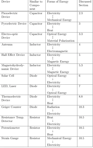
Chapters 2 - 10 comprise the rst part of this book. As mentioned above, they survey various direct energy conversion processes which convert to or from electricity and which do not involve magnets and coils. Table 1.1 lists many of the processes studied along with where in the text they are discussed, and Table 1.2 lists some of the devices detailed. This text is not intended to be encyclopedic or complete. Instead, it is intended to highlight the physics behind some of the most widely available and accessible energy conversion devices which convert to or from electrical energy. One way to understand energy conversion devices used to convert to or from electricity is to classify them as most similar to capacitors, inductors, resistors, or diodes. While not all devices t neatly in these categories, many do. The second column of Table 1.2 lists the category for various devices. Similarly, energy conversion processes may be capacitive, inductive, resistive, or diode-like.
magnetohy-Process Forms of
Energy ExampleDevices Discussedin Section Piezoelectricity Electricity
l
Mechanical Energy
Piezoelectric Vibration Sensor, Electret Microphone
2.3
Pyroelectricity Electricity
l
Heat
Pyroelectric Infrared Detector
3
optic Eect Optical Electro-magnetic
Energy
l
Material Polarization
Controllable Optics, Liquid Crystal Displays
3.3
Electromagnetic Transmission and Reception
Electricity
l
Electromagnetic Energy
Antenna 4
Hall Eect Electricity
l
Magnetic Energy
Hall Eect
Device 5
Magnetohydrody-namic Eect Electricityl
Magnetic Energy
Magnetohydrody-namic
Device
5.3
Absorption Optical Electro-magnetic
Energy
↓
Electricity
Solar cell, Semiconductor Optical
Photodetector 6
Process Forms of
Energy ExampleDevices Discussedin Section Spontaneous
Emission Electricity↓
Optical Electro-magnetic
Energy
Lamp, LED 7.3
Stimulated
Emission Electricity↓
Optical Electro-magnetic
Energy
Laser, Optical
Amplier 7.4
Thermoelectric Eects (Incl. Seebeck, Peltier and Thomson)
Electricity
l
Heat
Thermoelectric cooler, Peltier device,
Thermocouple
8.8
(Battery or Fuel
Cell) Discharging ChemicalEnergy
↓
Electricity
Battery, Fuel
Cell 9
(Battery or Fuel
Cell) Charging Electricity↓
Chemical Energy
Battery, Fuel
Cell 9
Thermionic
Emission Heat↓
Electricity
Thermionic
Device 10.2
Electrohydrody-namic Eect Electricityl
Fluid ow
Microuidic
Pump, Valve 10.6
Device Similar to Compo-nent
Forms of Energy Discussed Section
Piezoelectric
Device Capacitor Electricityl
Mechanical Energy
2.3
Pyroelectric Device Capacitor Electricity
l
Heat
3
Electro-optic
Device Capacitor Optical Energyl
Material Polarization 3.3
Antenna Inductor Electricity
l
Electromagnetic
4
Hall Eect Device Inductor Electricity
l
Magnetic Energy
5
Magnetohydrody-namic Device Inductor Electricityl
Magnetic Energy
5.3
Solar Cell Diode Optical Energy
↓
Electricity
6
LED, Laser Diode Electricity
↓
Optical Energy
7
Thermoelectric
Device Diode Electricityl
Heat
8.8
Geiger Counter Diode Radiation
↓
Electricity
10.3
Resistance Temp.
Detector Resistor Heat↓
Electricity
10.5
Potentiometer Resistor Electricity
↓
Heat
10.5
Strain Gauge Resistor Mechanical Energy
↓
Electricity
[image:17.504.71.439.74.660.2]10.5
drodynamic device converts kinetic energy of a conducting material in the presence of a magnetic eld into electricity.
Optical devices are discussed in Chapters 6 and 7. These chapters dis-cuss devices made from diode-like pn junctions such as solar cells, LEDs, and semiconductor lasers as well as other types of devices such as incandes-cent lamps and gas lasers. Thermoelectric devices convert a temperature dierential into electricity [3, p. 146]. They are also made from junctions of materials in which heat and charges ow at dierent rates, and they are discussed in Chapter 8. Batteries and fuel cells are discussed in Chapter 9. A battery is a device which stores energy as a chemical potential. Batteries range in size from tiny hearing aid button sized batteries which store tens of milliamp-hours of charge to large car batteries which can store 10,000 times as much energy. A fuel cell is a device which converts chemical en-ergy to electrical enen-ergy through the oxidation of a fuel [3]. During battery operation, the electrodes are consumed, and during fuel cell operation, the fuel and oxidizer are consumed instead. A variety of resistor-like energy conversion devices, among other devices, are discussed briey in Chapter 10.
1.3 Conservation of Energy
Energy conservation is one of the most fundamental ideas in all of sci-ence and engineering. Energy can be converted from one form to another. For example, kinetic energy of a moving ball can be converted to heat by friction, or it can be converted to potential energy if the ball rolls up a hill. However, energy cannot be created or destroyed. The idea of energy conservation will be considered an axiom, and it will not be questioned throughout this book. Sometimes people use somewhat loose language when describing energy conversion. For example, one might say that en-ergy is lost to friction when a moving block slides along a table or when electricity ows through a resistor. In both cases, the energy is not lost but is instead converted to heat. Thermoelectric devices and pyroelectric devices can convert a temperature dierential back to electricity. Someone might say that energy is generated by a coal power plant. What this phrase means is that chemical energy stored in the coal is converted to electrical energy. When a battery is charged, electrical energy is converted back to chemical energy. This imprecise language will occasionally be used in the text, but in all cases, energy conservation is assumed. While it might seem like an abstract theoretical law, energy conservation is used regularly by cir-cuit designers, mechanical engineers modeling mechanisms, civil engineers designing pipe systems, and other types of engineers.
Eciency of an energy conversion device,ηef f, is dened as the power
output of the desired energy type over the power input.
ηef f =
Pout
Pin (1.1)
1.4 Measures of Power and Energy
This book brings together topics from a range of elds including chemistry, electrical engineering, and thermodynamics. Scientists in each branch of study use symbols to represent specic quantities, and the choice of vari-ables by scientists in one eld often contradict the choice by scientists in another eld. In this text, dierent fonts are used to represent dierent symbols. For example, S represents entropy, $ represents the Seebeck
co-ecient, andS represents action. A list of variables used in this text along
with their units can be found in Appendix A. Use the tables in the appendix as tools.
PowerP and energy E are fundamental measures. Power absorbed by
a system is the derivative of the energy absorbed with respect to time.
P = dE
dt (1.2)
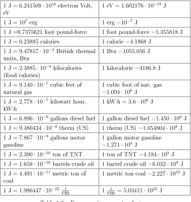
In SI units, energy is measured in joules and power is measured in watts. While these are the most common measures, many other units are used. Every industry, from the petroleum industry to the food industry to the electrical power industry, seems to have its own favorite units. Tables 1.3 and 1.4 list energy and power conversion factors. Values in the tables are from references [7] and [8].
Conversions between joules and some units, including calories, ergs, kilowatt hours, and tons of TNT are exact denitions [7]. The calorie is approximately the energy needed to increase the temperature of one gram of water by a temperature of one degree Celsius, but it is dened to be 4.1868 J [7]. Note that there is both a calorie and food calorie (also
called kilocalorie). The food calorie or kilocalorie is typically used when specifying the energy content of foods, and it is a thousand times as large as the (lowercase c) calorie. Other conversions listed in Table 1.3, including the conversion for energy in barrels of crude oil, are approximate average values instead of exact denitions [8]. Values in Table 1.3 are listed to the signicant precision known or to four signicant digits. Other inexact values throughout this text are also specied to four signicant digits. The unit 1
1 J= 6.241508·1018 electron Volt,
eV 1 eV= 1.602176·10
−19 J
1 J= 107 erg 1 erg =10−7 J
1 J=0.7375621 foot pound-force 1 foot pound-force =1.355818J
1 J= 0.23885 calories 1 calorie =4.1868 J
1 J= 9.47817·10−4 British thermal
units, Btu 1 Btu =1055.056 J
1 J= 2.3885·10−4 kilocalories
(food calories) 1 kilocalorie =4186.8 J
1 J= 9.140·10−7 cubic feet of
natural gas 1 cubic foot of nat. gas=1.094·106 J 1 J= 2.778·10−7 kilowatt hour,
kW·h
1 kW·h= 3.6·106 J
1 J= 6.896·10−9 gallons diesel fuel 1 gallon diesel fuel =1.450·108 J 1 J= 9.480434·10−9 therm (US) 1 therm (US) =1.054804·108 J 1 J= 7.867·10−9 gallons motor
gasoline 1 gallon motor gasoline=1.271·108 J 1 J= 2.390·10−10 ton of TNT 1 ton of TNT =4.184·109 J 1 J= 1.658·10−10 barrels crude oil 1 barrel crude oil =6.032·109 J 1 J= 4.491·10−11 metric ton of
coal 1 metric ton coal =2.227·10
10 J
1 J= 1.986447·10−23 1
cm 1 cm1 = 5.03411·1022 J
Table 1.3: Energy unit conversion factors.
1 W= 1 Js 1 Js = 1 W
1 W= 1·107 erg
s 1 ergs = 10−7 W
1 W= 1.34·10−3 horsepower 1 horsepower =7.46·102 W 1 W= 2.655224·103 foot
pound-force per h 1 foot pound-force per h= 3.766161·10−4 W
[image:21.504.62.443.72.476.2]1.5 Properties of Materials
1.5.1 Macroscopic PropertiesTo understand energy conversion devices, we need to understand materi-als both microscopically on the atomic scale and macroscopically on large scales. A macroscopic property is a property that applies to large pieces of the material as opposed to microscopic sized pieces.
One way to classify materials is based on their state of matter. Materials can be classied as solids, liquids, gases, or plasmas. A plasma is an ionized gas. Other more unusual states of matter exist such as Bose Einstein condensates, but they will not be discussed in this book.
Crystalline Amorphous Polycrystalline
Figure 1.1: Illustration of crystalline, amorphous, and polycrystalline atomic structure.
mate-rial may dier. Electrons can ow more easily through a pure crystalline material while electrons are more likely to be scattered or absorbed as they ow through an amorphous material, crystalline materials with impurities, or a crystalline material with crystal defects.
We can further classify crystals as either isotropic or anisotropic [10, p. 210]. A crystal is isotropic if its macroscopic structure and material properties are the same in each direction. A crystal is anisotropic if the macroscopic structure and material properties are dierent in dierent di-rections.
We can also classify materials based on how they behave when a voltage is applied across the material [11]. In a conductor, electrons ow easily in the presence of an applied voltage or electric eld. In an insulator, also called a dielectric, electrons do not ow in the presence of an applied voltage or electric eld. In the presence of a small external voltage or electric eld, a semiconductor acts as an insulator, and in the presence of a strong voltage or electric eld, a semiconductor acts as a conductor. Both solids and liquids can be conductors, and both solids and liquids can be insulators. For example, copper is a solid conductor while salt water is a liquid conductor.
1.5.2 Microscopic Properties
The electron conguration lists the energy levels occupied by electrons around an atom. The electron conguration can describe neutral or ion-ized atoms, and it can describe atoms in the lowest energy state or excited atoms. For example, the electron conguration of a neutral aluminum atom in the lowest energy state is 1s22s22p63s23p1. The electron conguration
of an aluminum Al+ ion in the lowest energy state is
1s22s22p63s2, and the
electron conguration of a neutral aluminum atom with an excited electron can be written as 1s22s22p63s24s1.
most energy to remove. However, there are exceptions to this idea for some electrons around larger atoms [13] [14].
Azimuthal quantum numbers are integers, and these values dene sub-shells. For shells with principle quantum numbern, the azimuthal quantum
number can take values from 0 ton−1. In the electron conguration, values
of this quantum number are denoted by lowercase letters: s=0, p=1, d=2, f=3, and so on. Magnetic quantum numbers are also integers, and these values dene orbitals. For a subshell with azimuthal quantum number l,
the magnetic quantum number takes values from −l to l. In the electron
conguration, superscript numbers indicate the magnetic quantum num-ber. Spin quantum numbers of electrons can take the values 1
2 and − 1 2 .
They are not explicitly denoted in the electron conguration.
Consider again the neutral aluminum atom in the lowest energy state. This atom has electrons with principle quantum numbers n=1, 2, and 3.
For electrons with principle quantum number 1, the only possible values for both the azimuthal quantum number and the magnetic quantum number are zero. The spin quantum number can take the values of 1
2 and − 1
2 . Only
two electrons can occupy the 1 shell, and these electrons are denoted by the 1s2 term of the electron conguration. For the electrons with principle
quantum number 2, the azimuthal quantum number can be 0 or 1. Two electrons can occupy the 2s orbital, and six electrons can occupy the 2p orbital. For the 3 shell, the azimuthal quantum number can take three possible values: s=0, p=1, and d=2. However since aluminum only has 13 electrons, electrons do not have all of these possible values, so the 3 shell is only partially lled. The atoms in the rightmost column of the periodic table have completely lled shells. They are rarely involved in chemical reactions because adding electrons, removing electrons, or forming chemical bonds would require too much energy.
Valence electrons are the electrons that are most easily ripped o an atom. Valence electrons are the electrons involved in chemical reactions, and electrical current is the ow of valence electrons. Other, inner shell, electrons may be involved in chemical reactions or electrical current only in cases of unusually large applied energies, and these situations will not be discussed in this text. Valence electrons occupy the subshell or subshells with the highest quantum numbers, and valence electrons are not part of completely lled shells. For the example of the neutral aluminum atom in the lowest energy state, the three electrons in the 3 shell are valence electrons.
is likely to be found spatially around an atom. However, identifying the location of an electron with any degree of precision is dicult for multiple reasons. First, atoms are tiny, roughly 10−10 m in diameter. Second, at
any temperature above absolute zero, atoms and electrons are continually in motion. Third, electrons have both particle-like and wave-like properties. Fourth, according to Heisenberg's Uncertainty Principle, the position and momentum of an electron cannot simultaneously be known with complete precision. At best, you can say that an electron is most likely in some region and moves with some range of speed. Fifth, in many materials including conductors and semiconductors, valence electrons are shared by many atoms instead of bound to an individual atom [10, p. 544].
1.6 Electromagnetic Waves
1.6.1 Maxwell's EquationsIn this text, V and I denote DC voltage and current respectively while v
and i denote AC or time varying voltage and current. In circuit analysis,
we are unconcerned with what happens outside these wires. We are only interested in node voltages and currents through wires. Furthermore, the voltages and currents in the circuit are described as functions of time t
but not position (x, y, z). Devices like resistors, capacitors, and inductors
too are assumed to be point-like and not extended with respect to position
(x, y, z). This set of assumptions is just a model. In reality, if two nodes in
a circuit have a voltage dierence between them, then necessarily a force is exerted on nearby charges not in the path of the circuit. This force per unit charge is the electric eld intensity −→E. Similarly, if there is current
owing through a wire, there is necessarily a force exerted on electrons in nearby loops of wire, and this force per unit current element is the magnetic ux density −→B. Energy can be stored in an electric or magnetic eld. In
later chapters, we will discuss devices, including antennas, electro-optic devices, photovoltaic devices, lamps, and lasers, that convert energy of an electromagnetic eld to or from electricity.
Four interrelated vector quantities are used to describe electromagnetic elds. These vector elds are functions of position(x, y, z)and time t. The
four vector elds are
− →
E(x, y, z, t)=Electric eld intensity in V
m
− →
D(x, y, z, t)=Displacement ux density in C
− →
H(x, y, z, t)=Magnetic eld intensity in A
m
−
→B(x, y, z, t)=Magnetic ux density in Wb
m2
In these expressions, V represents the units volts, C represents the units coulombs, A represents the units amperes, and Wb represents the units webers. Additional abbreviations for units are listed in Appendix B.
Coulomb's law
− →
F = Q1Q2ˆar
4πr2 (1.3)
tells us that charged objects exert forces on other charged objects. In this expression,Q1 and Q2 are the magnitude of the charges in coulombs. The
quantity is the permittivity of the surrounding material in units farads
per meter, and it is discussed further in Sections 1.6.3 and 2.2.3. The quantity r is the distance between the charges in meters, and ˆar is a unit
vector pointing along the direction between the charges. Force in newtons is represented by −→F. Opposite charges attract, and like charges repel.
Electric eld intensity is force per unit charge, so the electric eld intensity due to a point charge is given by
− →
E = Qˆar
4πr2 (1.4)
These vector elds can describe forces on charges or currents in a circuit as well as outside the path of a circuit. Maxwell's equations relate time varying electric and magnetic elds. Maxwell's equations in dierential form are:
− →
∇ ×−→E =−∂
− →
B
∂t Faraday's Law (1.5)
− →
∇ ×−→H =−→J + ∂
− →D
∂t Ampere's Law (1.6)
− →
∇ ·−→D =ρch Gauss's Law for the Electric Field (1.7)
− →
∇ ·−→B = 0 Gauss's Law for the Magnetic Field (1.8)
The additional quantities in Maxwell's equations are the volume current density−→J in Am2 and the charge densityρch in Cm3. In this text, we will not
The quantity −→∇ is called the del operator. In Cartesian coordinates, it
is given by
− →
∇ = ˆax
∂
∂x + ˆay
∂
∂y + ˆaz
∂
∂z. (1.9)
When this operator acts on a scalar function,−→∇f, it is called the gradient.
The gradient of a scalar function returns a vector representing the spatial derivative of the function, and it points in the direction of largest change in that function. In Maxwell's equations,−→∇ acts on vector, instead of scalar,
functions. The operation−→∇ ×−→E is called the curl, and the operation−→∇ ·−→E
is called the divergence. Both of these operations represent types of spatial derivatives of vector functions. The del operator obeys the identity
∇2 =−→∇ ·−→∇. (1.10)
The operation ∇2f is called the Laplacian of a scalar function, and it
represents the spatial second derivative of that function.
1.6.2 Electromagnetic Waves in Free Space
Electromagnetic waves travel through empty space at the speed of light in free space, c = 2.998·108 m
s , and through other materials at speeds less thanc. For a sinusoidal electromagnetic wave, the speed of propagation is
the product of the frequency and wavelength
|−→v| =f λ (1.11)
where|−→v |is the magnitude of the velocity in ms, f is the frequency in Hz,
and λ is the wavelength in meters. In free space, Eq. 1.12 becomes
c=f λ. (1.12)
The speed of light in free space is related to two constants which describe free space.
c= √1
0µ0 (1.13)
The permittivity of free space is given by 0 = 8.854 · 10−12 m whereF
F represents farads, and the permeability of free space is given by µ0 = 1.257 ·10−6 m where H represents henries. (Constants specied in thisH
section and in Appendix A are rounded to four signicant digits.)
In free space, the electric eld intensity −→E and the displacement ux
density−→D are related by 0.
− →D =
Relatedly in free space, the magnetic eld intensity −→H and the magnetic
ux density −→B are related by µ0.
− →
B =µ0−→H (1.15)
.
1.6.3 Electromagnetic Waves in Materials
Electromagnetic elds interact very dierently with conductors and with insulators. Electromagnetic elds do not propagate into perfect conduc-tors. Instead, charges and currents accumulate on the surface. While no materials are perfect conductors, commonly encountered metals like cop-per and aluminum are very good conductors. When these materials are placed in an external electromagnetic eld, surface charges and currents build up, and the electromagnetic eld in the material quickly approaches zero. Electromagnetic elds propagate through perfect insulators for long distances without decaying, and no charges or currents can accumulate on the surface because there are no electrons free from their atoms. In practical dielectrics, electromagnetic waves propagate long distances with very little attenuation. For example, optical electromagnetic waves remain strong enough to detect after propagating hundreds of kilometers through optical bers made of pure silicon dioxide [10, p. 886].
Resistance R in ohms, capacitance C in farads, and inductance L in
henries describe the electrical properties of devices. Resistivity ρ in Ωm,
permittivity in Fm, and permeabilityµ in Hm describe the electrical
prop-erties of materials. The quantitiesρ, ,andµdescribe properties of
materi-als alone while the quantitiesR, C, andLincorporate eects the material,
shape, and size of a device.
Resistivity ρ is a measure of the inability of charges or electromagnetic
waves to propagate through a material. Conductors have a very small resistivity while insulators have a large resistivity. Sometimes electrical conductivity, σ = 1ρ in units Ω1m, is used in place of the resistivity. For a
device made of a uniform material with length l and cross sectional area A,resistance and resistivity are related by
R= ρl
A. (1.16)
Parallel Plate Capacitor Partial Turn Inductor
dthick
l
w
dthick
l
w
Figure 1.2: Geometry of a parallel plate capacitor and partial turn inductor.
Permeability µis a measure of the ability of a material to store energy
in the magnetic eld due to currents distributed throughout the material. Materials can also be described by their relative permeabilityµr, a unitless
measure.
µr =
µ
µ0 (1.17)
While permeability describes a material, inductance describes a device. The magnetic ux density in a material is a scaled version of the magnetic eld intensity.
− →
B =µ−→H (1.18)
Often insulators have permeabilities close to µ0 while conductors used to
make permanent magnets have signicantly larger permeabilities. The right part of Fig. 1.2 shows a partial turn coil in a vacuum with lengthl,thickness dthick, and width w. The inductance and permeability of this device are
related by [11, p. 311]
L= µdthickl
w . (1.19)
Permittivity is a measure of the ability of a material to store energy
as an electric eld due to charge separation distributed throughout the material. Materials can also be described by their relative permittivity r,
a unitless measure.
r =
0 (1.20)
The displacement ux density in a material is a scaled version of the electric eld intensity.
− →
D =−→E (1.21)
A uniform parallel plate capacitor with cross sectional area of plates
A = l·w and distance between plates dthick, is shown on the left part of
Fig. 1.2, and it has capacitance
C = A
dthick (1.22)
where is the permittivity of the insulator between the plates.
Permittivity, permeability, and resistivity, depend on frequency. In some contexts, the frequency dependence can be ignored, and through-out most of this text, these quantities will be assumed to be constants. In other contexts, the frequency dependence can be quite signicant. For example, the permittivity of semiconductor materials is a strong function of frequency for frequencies close to the semiconductor energy gap. The permittivity(ω)and resistivityρ(ω)are not independent. If one of them is
known as a function of frequency andµis assumed constant, the other can
be derived. This relationship is known as the Kramers Kronig relationship [10] or occasionally as the dielectric dispersion formula [15].
When discussing electrical properties of a device, resistance, inductance, and capacitance are combined into one complex measure, the impedance. Similarly, some authors nd it convenient to combine resistivity, permit-tivity, and permeability into a pair of complex measures of the electrical properties of materials [6]. The complex permittivity is dened∗ =+jρ,
and the complex permeability is dened µ∗ = µ+jρmag . The quantity
ρ represents the resistivity which is a measure of the energy converted to
heat as a charge ows through a material due to an applied electrical eld. The quantityρmag represents an analogous measure of energy converted to
1.7 Problems
1.1. A Ford Focus produces 160 horsepower [16]. Calculate the power produced in watts, and calculate the approximate energy produced by the vehicle in one hour.
1.2. A gallon of gas contains 1.21· 105 Btu and weighs 6 pounds [8].
Calculate the energy stored in the gallon of gas in joules, and calculate the specic energy in joules per kilogram.
1.3. An Oreo cookie has 53 food calories and weighs 11 grams [17]. A ton (2000 pounds) of TNT contains approximately4.184·109 J of energy
[7]. Calculate the specic energy of the cookie in joules per kilogram, and calculate the specic energy of the TNT in joules per kilogram. (Yes, the value for the cookie is higher.)
1.4. Find the electron conguration of an isolated indium atom in the lowest energy state. How many electrons are found around the atom? Repeat for a Cl− ion.
1.5. Use a periodic table for this problem.
(a) Which element has the electron conguration
1s22s22p63s23p64s23d2?
Part I
Survey of Energy Conversion
Devices
2 Capacitors and Piezoelectric Devices
2.1 Introduction
This chapter begins with a discussion of material polarization, and then it discusses capacitors and piezoelectric devices. The next chapter discusses pyroelectric devices and electro-optic devices. All of these devices are all constructed from a thin dielectric layer, and operation of all of these devices involves establishing a material polarization, charge build up, throughout this dielectric material. In piezoelectric materials, mechanical strain causes a material polarization. As with many energy conversion devices, piezoelec-tric devices can work both ways, converting mechanical energy to elecpiezoelec-tricity or converting electricity to mechanical vibrations. In pyroelectric devices, a temperature gradient causes the material polarization, and in electro-optic devices, an external optical electric eld causes the material polarization.
Why start the discussion of energy conversion devices with a discussion of capacitors? Capacitors are familiar to electrical engineers, and they are energy storage devices. How do capacitors work? What are the components of a capacitor? What materials are capacitors made out of? What are the dierences between dierent types of capacitors such as mica capacitors and electrolytic capacitors? In an introductory circuits course, a capacitor is a device where the relationship between the current i and voltage v is
given by
i=Cdv
dt (2.1)
and the capacitanceC is just a constant. The only dierence between one
2.2 Capacitors
2.2.1 Material Polarization
When an external voltage is applied across an insulator, charges separate throughout the material, and this charge separation is called a material polarization. Material polarization can be dened more precisely in terms of the electric eld intensity −→E and the displacement ux density −→D, two
vector elds which show up in Maxwell's equations, Eqs. 1.5 - 1.8. These vector elds are related by
− →
D =−→E . (2.2)
Why do we dene two electric eld parameters when they are just scaled versions of each other? It is useful to separate the description of the elec-tric eld inside a material from the description of the eld in free space. Similarly, two vector elds describe magnetic eld, the magnetic eld inten-sity−→H and magnetic ux density−→B, and these elds show up in Maxwell's
equations for the same reason. Material polarization, −→P in units Cm2, is
dened as the dierence between the electric eld in the material −→D and
the electric eld that would be present in free space→−E . More specically,
− →
P =−→D −0−→E (2.3)
or −→
P = (−0)−→E . (2.4)
These expressions involve the permittivity of free space0 and the
permit-tivity of a material which were dened in Sec. 1.6.3.
Scientists overload both the words capacitance and polarization with multiple meanings. See Appendix C for more details on the dierent uses of these terms.
2.2.2 Energy Storage in Capacitors
When a capacitor is charged, energy is converted from electrical energy to energy stored in a material polarization which is energy of the charge sep-aration. When it is discharged, energy is converted from energy stored in the material polarization back to electrical energy of owing electrons. Ca-pacitors are made from an insulating material between conducting plates. As we supply a voltage across the insulator, charges accumulate on the plates. The voltage built up is proportional to the charge accumulated on the plates.
In Eq. 2.5,Qis the charge in coulombs,v is the voltage, and the constant of
proportionality is the capacitanceCin farads. If we take the derivative with
respect to time, we get the more familiar expression relating the current and voltage across the capacitor.
dQ
dt =i=C
dv
dt (2.6)
The capacitance of a capacitor is related to the permittivity of the dielectric material between the conductors. Permittivity is a measure of the amount of energy that can be stored by a dielectric material. As described by Eq. 1.22, for a parallel plate capacitor this relationship is
C = A
dthick (2.7)
where A is the area of the plates and dthick is the distance between the
plates. The energyE stored in a capacitor as a function of voltage applied
across it is given by
E = 1
2Cv 2 = 1
2Qv. (2.8)
The capacitance of a vacuum-lled parallel plate capacitor is described by Eq. 2.7 with permittivity = 0, the permittivity of free space. As we
charge the capacitor, charges accumulate on the plates, and no change occurs to the vacuum between the plates. If we replace the vacuum with a dielectric with > 0, the capacitance becomes larger. The dielectric
lled capacitor can store more energy, all else equal, because the dielectric material changes as the capacitor charges. More specically, the material polarizes. In an insulator, electrons are bound to their atoms, and current cannot ow. Instead, the electrons in a dielectric move slightly with respect to their nuclei while still staying bound to the atoms. Electrons are always in motion for materials at temperatures above absolute zero, but when a material polarizes, the net location of electrons with respect to the nuclei changes. As the capacitor charges, the electrons are slightly displaced from their atoms, balancing the charges on the plates, and more energy is stored in the dielectric for a given voltage. We say that this process induces electric dipoles. The larger the permittivity, , the more the material can
store energy by polarizing in this way. For this reason, capacitors are often lled with dielectric materials like tantalum dioxide Ta2O5 which has
= 250 [18]. A material with = 250, for example, will be able to store
2.2.3 Permittivity and Related Measures
For historical reasons, the permittivity may be expressed by dierent mea-sures. The electric susceptibility χe, relative permittivity r, index of
re-fraction n, and permittivity all describe the ability of a material to store
energy in the electric eld. Electric susceptibility is a unitless measure related to the permittivity by
χe =
0 −
1 (2.9)
and relative permittivity is another unitless measure dened by
r =
0
. (2.10)
With some algebra, we can write the material polarization in terms of the relative permittivity or the electric susceptibility.
− →P = (
r−1)0−→E =0χe−→E (2.11)
Scientists studying optics often use index of refraction, another unitless measure which represents the ratio of the speed of light in free space to the speed of light in the material.
n= c
|−→v| =
speed of light in free space
speed of light in material (2.12)
Since electromagnetic waves cannot travel faster than the speed of light in free space, index of refraction of a material is greater than one, n> 1.
Assuming a material is a good insulator and µ = µ0, which are typically
safe assumption for optics, the relationship between index of refraction and permittivity simplies to
n=√r. (2.13)
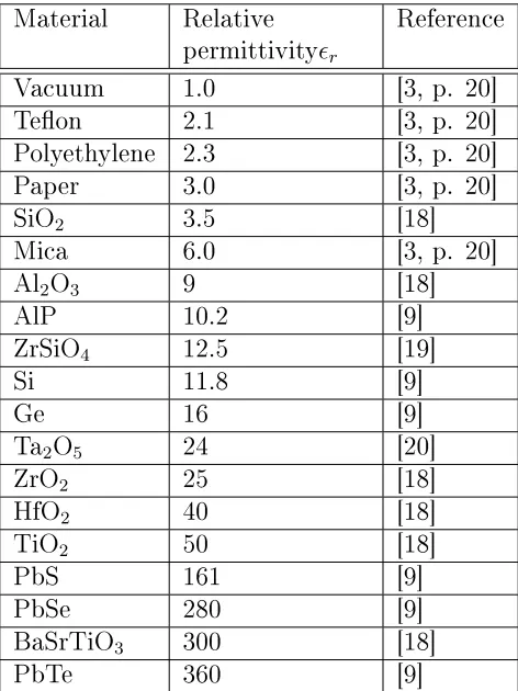
Table 2.1 lists relative permittivities of some insulators used to make capacitors or piezoelectric devices. The values are all approximates. See the references cited for more detailed information.
Material Relative permittivityr
Reference
Vacuum 1.0 [3, p. 20]
Teon 2.1 [3, p. 20]
Polyethylene 2.3 [3, p. 20]
Paper 3.0 [3, p. 20]
SiO2 3.5 [18]
Mica 6.0 [3, p. 20]
Al2O3 9 [18]
AlP 10.2 [9]
ZrSiO4 12.5 [19]
Si 11.8 [9]
Ge 16 [9]
Ta2O5 24 [20]
ZrO2 25 [18]
HfO2 40 [18]
TiO2 50 [18]
PbS 161 [9]
PbSe 280 [9]
BaSrTiO3 300 [18]
[image:37.504.134.370.194.509.2]PbTe 360 [9]
ˆ ax
ˆ ay
ˆ az
No applied voltage With applied voltage
Figure 2.1: Illustration of material polarization.
In such cases, the material is called anisotropic. Permittivity of anisotropic materials is more accurately described by a matrix.
xx xy xz
yx yy yz
zx zy zz
The left part of Fig. 2.1 shows some atoms of a crystal. The small black circles represent the location of the nuclei of atoms in the crystals, and the gray circles represent the electron cloud surrounding the nuclei of each atom. If an electric eld is applied in the ˆaz direction, the material
po-larizes, so the electrons are slightly displaced with respect to the nuclei as shown in the gure on the right. Since the spacing of atoms is dierent in theaˆx andaˆy direction than theaˆz direction, the external eld required to
get the same charge displacement will be dierent in the ˆax and ˆay
direc-tions than theaˆz direction for this material. For this reason, the material
illustrated in the gure is anisotropic, and the permittivity is best described by a matrix as opposed to a scalar quantity.
2.2.4 Capacitor Properties
Capacitors are energy conversion devices used in applications from stabiliz-ing power supplies, to lterstabiliz-ing communication signals, to separatstabiliz-ing out a DC oset from an AC signal. Though capacitors and batteries both store electrical energy, energy in batteries is stored in the chemical bonds of atoms of the electrodes while energy is stored in capacitors in the material polarization from bound charges shifting in a dielectric layer.
Figure 2.2: Range of capacitance and maximum voltage values for various capacitor types, following [21] and [22].
be damaged if it is placed in a circuit where the voltage across it exceeds the maximum rated value. Approximate ranges for these parameters for capacitors with dierent dielectric materials are shown in Fig. 2.2. Capac-itance ranges are on the vertical axis, and maximum voltage ranges are on the horizontal axis. For example, electrolytic capacitors often can be found with capacitance values ranging from 10−7 to 1 F and maximum voltage
ratings in the range of 1 to 1000 V. Similarly, ceramic capacitors can of-ten be found with capacitance values ranging from 10−13 to 5·10−4 F and
maximum voltage ratings in the range of 1 to 50,000 V.
While capacitance and maximum voltage rating are important param-eters to consider, they are not the only considerations. Another factor to consider is temperature stability. Ideally, the capacitance will be indepen-dent of temperature. However, all materials have a nonzero temperature coecient. Ceramic and electrolytic capacitors tend to be more sensitive to temperature variation than polymer or vacuum capacitors [22]. Accuracy, or precision, is also important. Just as resistors are labeled with tolerances, capacitors may have tolerances of, for example, ±5% or ±10%. Another
Figure 2.3: Natural mica.
as an ideal capacitor in series with an ideal resistor, and the value of the resistor used is called the equivalent series resistance. Also, leakage of a capacitor should be considered [22]. If a capacitor is able to retain its stored charge for a long period of time, the capacitor has small leakage. If the capacitor discharges quickly even when disconnected from a circuit, it has large leakage. An ideal capacitor has no leakage [22]. Capacitors are also dierentiated by their lifetime. An ideal capacitor operates for decades without degradation. However, some types of capacitors, such as electrolytic capacitors, are not designed to have long lifetimes [22]. Other factors to consider include cost, availability, size, and frequency response [22].
Ceramics, glasses, polymers, and other materials are used as the di-electric [22]. Often capacitors are classied by the didi-electric material they contain [22]. Ceramic capacitors are small, cheap, and readily available [22]. They can often tolerate large applied voltages [22]. They typically have small capacitance values, poor accuracy, poor temperature stability and moderate leakage [22]. They have low equivalent series resistance and can withstand a lot of current, but they can cause transient voltage spikes, [23, ch. 1]. Some ceramic capacitors are piezoelectric. If these capacitors are vibrated, or even tapped with a pencil, noise will be introduced in the circuit due to piezoelectricity [23, ch. 12].
Mica is an interesting material which is used as a dielectric in capacitors. Figure 2.3 shows naturally occurring mica collected at Ruggles Mine near Grafton, New Hampshire. Mica comes in dierent natural forms including biotite and muscovite KAl2(AlSi3O10)(OH)2 [24]. Mica is a aky mineral
with a layered structure [24], so mica capacitors can be made with very thin dielectric layers. Mica capacitors often have good accuracy and small leakage [22].
in-Figure 2.4: Through-hole size capacitors.
cluding polystyrene, polycarbonate, polyester, polypropylene, Teon, and mylar [22]. These capacitors often have good accuracy, temperature stabil-ity, and leakage characteristics [22].
Not all capacitors have solid dielectrics. A vacuum is a dielectric. Ca-pacitors with a vacuum dielectric are used in applications which involve high voltage or which require very low leakage [22]. Capacitors with liq-uid dielectrics made of oil are used in similar situations [22]. Electrolytic capacitors often have dielectrics which are a combination of solid materi-als with liquid electrolytes. An electrolyte is a liquid through which some charges can ow more easily than others. Electrolytic capacitors are polar-ized, meaning that they have positive and negative terminals, so, similar to a diode, the orientation of the capacitor in a circuit is important. Inside an electrolytic capacitor is a junction of multiple materials. The initial appli-cation of voltage in the factory chemically creates an oxide layer which is the dielectric. Reversing the voltage will dissolve the dielectric and destroy the capacitor. One advantage of electrolytic capacitors is that a small de-vice can have a large capacitance. However, they often have poor accuracy, temperature stability, and leakage [22]. Also, electrolytic capacitors have a nite lifetime because the liquid can degrade over time.
2.3 Piezoelectric Devices
Piezoelectric, pyroelectric, and electro-optic devices all involve this type of energy conversion, and they are all currently available as sensors and as other products. In piezoelectric devices, discussed in this section, a mechanical stress causes a material polarization.
If a large enough strain is exerted on a material, the crystal structure will change. For example, at high enough temperature and pressure, coal will crystallize into diamond, and when the pressure is removed, the mate-rial stays in diamond form. Steel can be hardened by repeatedly hitting it in a process called shot peening. A signicant amount of energy is needed to permanently change the crystal structure of a material. In this section, we are not discussing this eect. Instead, we are discussing an eect that typically requires little energy. When a mechanical strain is exerted on a piezoelectric device, a material polarization is established. The valence electrons are displaced, but the nuclei of the material and other electrons do not move. When we release the stress, the material polarization goes away.
2.3.1 Piezoelectric Strain Constant
We can describe the material polarization of a piezoelectric insulating ma-terial by incorporating a term which depends on the applied mechanical stress, [25].
− →
P =−→D−0−→E +d−→ς (2.14)
In this equation, −→P is material polarization in Cm2,
− →
D is displacement ux
density in Cm2, 0 is the permittivity of free space in Fm, −→E is the applied
electric eld intensity in Vm,dis the piezoelectric strain constant in mV , and
−
→ς is the stress in pascals. Stress can also be given in other units.
1 Pa= 1 mJ3 = 1
N
m2 (2.15)
For many materials, the piezoelectric strain constant d is zero, and for
many other materials, d is quite small. Barium titanate is used to make
piezoelectric sensors because it has a relatively large piezoelectric strain coecient, d ≈ 3·10−10 m
V [25, p. 408]. Additional example coecients are given in the next chapter in Table 3.1.
Mechanical strain is a unitless measure of deection or deformation while stress has units pascals. Without an external electric eld, these quantities are related by Young's elastic modulus which has units Nm2.
strain=
1
Young's elastic modulus
If an electric eld is also applied, stress and strain are related by
strain=
1
Young's elastic modulus
·stress+−→E ·d (2.17)
whered is the piezoelectric strain constant.
The energy stored in a piezoelectric device under stress −→ς is given by
E =|−→ς | ·A·l·ηef f (2.18)
whereAis the cross sectional area of a device in m2,l is the deformation in
m, andηef f is the eciency. Devices which are bigger, are deformed more,
or are made from materials with larger piezoelectric constants store more energy.
According to Eq. 2.14, the material polarization of an insulating crys-tal is linearly proportional to the applied stress. While this accurately describes many materials, it is a poor description of other materials. For other piezoelectric crystals, the material polarization is proportional to the square of the applied stress
− →
P
=
− →
D
−0
− →
E
+d|−
→ς |+dquad|−→ς |2 (2.19)
wheredquad is another piezoelectric strain constant. To model the material
polarization in other materials, terms involving higher powers of the stress are needed.
2.3.2 Piezoelectricity in Crystalline Materials
To understand which materials are piezoelectric, we need to introduce some terminology for describing crystals. Crystalline materials may be composed of elements, such as Si, or compounds, such as NaCl. By denition, atoms in crystals are arranged periodically. Two components are specied to describe the arrangement of atoms in a crystal: a lattice and a basis [25, p. 4]. A lattice is a periodic array of points in space. An n-dimensional
lattice is specied by n lattice vectors for integer n. We can get from one
lattice point to every other lattice point by traveling an integer number of lattice vectors. Three vectors,−→a1,−→a2,and→−a3, are used to describe physical
Basis
Lattice Crystal structure
− →a1 −
→a2
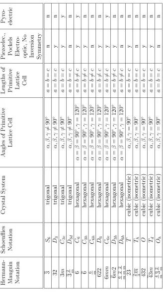
Figure 2.5: Two dimensional illustration of the terms lattice, basis, crystal structure, and primitive lattice vector.
To specify the structure of a material, we attach one or more atoms to every point in the lattice. This arrangement of atoms is called a crystal basis. The lattice and crystal basis together dene the crystal structure [25]. Figure 2.5 shows a two dimensional example of a lattice, crystal basis, and crystal structure. Since this example is two dimensional, only two lattice vectors are needed to specify the lattice. Two primitive lattice vectors are shown, and a primitive cell is shaded.
There are 14 possible three dimensional lattice types, and these are called Bravais lattices [25]. Each of these possible lattices has a descriptive name. Figure 2.6 shows four of the possible Bravais lattices: simple cubic, body centered cubic, face centered cubic, and asymmetric triclinic. In the simple cubic lattice, all angles between line segments connecting nearest neighbor points are right angles, and all lengths between nearest neighbor points are equal. In the asymmetric triclinic lattice, none of these angles are right angles, and none of these lengths between nearest neighbor points are equal. Figure 2.6 shows lattice cells, but the cells for the body centered cubic and face centered cubic lattices are not primitive cells because smaller repeating units can be found.
Consider some example lattices and crystal structures. The crystal structure of sodium chloride, for example, involves a face centered cubic lattice and a basis composed of one sodium and one chlorine atom. An-other example is silicon which crystallizes in what is known as the diamond structure [25]. This crystal structure involves a face centered cubic lattice and a basis composed of two silicon atoms, at location(0,0,0)and l
4, l 4,
Simple cubic: Body centered cubic:
[image:45.504.122.363.78.304.2]Face centered cubic: Asymmetric triclinic:
Figure 2.6: Illustration of some Bravais lattices.
wherel is the length of the primitive cell. Carbon, Si, Ge, and Sn all
crys-tallize in this diamond structure with cell lengths ofl = 0.356,0.543, 0.565,
and 0.646 nm respectively [25].
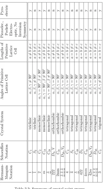
While there are only 14 possible three dimensional lattices, there are signicantly more possible crystal structures because the crystal structure also incorporates the basis. It is not possible to list all possible crystal structures. Instead, they are classied based on the symmetries they con-tain. Possible symmetry operations are 2-fold, 3-fold, 4-fold, and 6-fold rotations, horizontal and vertical mirror planes, and inversion. Crystal structures are grouped based on the symmetry elements they contain into classes called crystal point groups. There are 32 possible crystal point groups, and they are listed in the Table 2.2.
Hermann- Mauguin Notation Sc ho enies Notation Crystal System Angles of Primitiv e Lattice Cel l Lengths of Primitiv e Lattice Cell Piezo elec. , Po ck els Electro- optic, No In version Symmetry Pyro- electric 1 C1 triclinic α ,β ,γ 6 = 90 ◦ a 6 = b 6 = c y y 1 S2 triclinic α ,β ,γ 6 = 90 ◦ a 6 = b 6 = c n n 2 C2 mono clinic α ,γ = 90 ◦ ,β 6 = 90 ◦ a 6 = b 6 = c y y m C1 h mono clinic α ,γ = 90 ◦ ,β 6 = 90 ◦ a 6 = b 6 = c y y 2 m C2 h mono clinic α ,γ = 90 ◦ ,β 6 = 90 ◦ a 6 = b 6 = c n n 222 D2 , V orthorhom bic α ,β ,γ = 90 ◦ a 6 = b 6 = c y n 2mm C2 v orthorhom bic α ,β ,γ = 90 ◦ a 6 = b 6 = c y y 2 m 2 m 2 m D2 h ,V h orthorhom bic α ,β ,γ = 90 ◦ a 6 = b 6 = c n n 4 C4 tetragonal α ,β ,γ = 90 ◦ a = b 6 = c y y 4 S4 tetragonal α ,β ,γ = 90 ◦ a = b 6 = c y n 4 m C4 h tetragonal α ,β ,γ = 90 ◦ a = b 6 = c n n 422 D4 tetragonal α ,β ,γ = 90 ◦ a = b 6 = c y n 4 mm C4 v tetragonal α ,β ,γ = 90 ◦ a = b 6 = c y y 42 m D2 d ,V d tetragonal α ,β ,γ = 90 ◦ a = b 6 = c y n 4 m 2 m 2 m D4 h tetragonal α ,β ,γ = 90 ◦ a = b 6 = c n n 3 C3 trigonal α ,β ,γ 6 = 90 ◦ a = b = c y y
Hermann- Mauguin Notation Sc ho enies Notation Crystal System Angles of Primitiv e Lattice Cell Lengths of Primitiv e Lattice Cell Piezo elec ., Po ck els Electro- optic, No In version Symmetry Pyro- electric 3 S6 trigonal α ,β ,γ 6 = 90 ◦ a = b = c n n 32 D3 trigonal α ,β ,γ 6 = 90 ◦ a = b = c y n 3 m C3 v trigonal α ,β ,γ 6 = 90 ◦ a = b = c y y 3 2 m D3 d trigonal α ,β ,γ 6 = 90 ◦ a = b = c n n 6 C6 hexagonal α = β = 90 ◦ ,γ = 120 ◦ a = b 6 = c y y 6 C3 h hexagonal α = β = 90 ◦ ,γ = 120 ◦ a = b 6 = c y n 6 m C6 h hexagonal α = β = 90 ◦ ,γ = 120 ◦ a = b 6 = c n n 622 D6 hexagonal α = β = 90 ◦ ,γ = 120 ◦ a = b 6 = c y n 6 mm C6 v hexagonal α = β = 90 ◦ ,γ = 120 ◦ a = b 6 = c y y 6 m 2 D3 h hexagonal α = β = 90 ◦ ,γ = 120 ◦ a = b 6 = c y n 6 m 2 m 2 m D6 h hexagonal α = β = 90 ◦ ,γ = 120 ◦ a = b 6 = c n n 23 T cubic (isome tri c) α ,β ,γ = 90 ◦ a = b = c y n
2 m 3
Th cubic (isome tri c) α ,β ,γ = 90 ◦ a = b = c n n 432 O cubic (isome tri c) α ,β ,γ = 90 ◦ a = b = c y n 43 m Td cubic (isome tri c) α ,β ,γ = 90 ◦ a = b = c y n
[image:47.504.91.419.67.661.2]4 3 m 2 m Oh cubic (isome tri c) α ,β ,γ = 90 ◦ a = b = c n n
Figure 2.7: Shapes used to illustrate symmetry elements.
As an example of identifying symmetry elements, consider the 2D shapes in Fig. 2.7. The T-shaped gure has one symmetry element, a mirror plane symmetry. The shape looks the same if it is reected over the mirror plane shown in the gure by a dotted line. The Q-shape has no symmetry ele-ments. The hexagon has multiple symmetry eleele-ments. It contains 2-fold rotation because it looks the same when rotated by180◦. It also has 3-fold
and 6-fold rotation symmetries because it looks the same when rotated by
60◦
![Figure 2.2: Range of capacitance and maximum voltage values for variouscapacitor types, following [21] and [22].](https://thumb-us.123doks.com/thumbv2/123dok_us/8373.500/39.504.75.435.83.317/figure-range-capacitance-maximum-voltage-values-variouscapacitor-following.webp)