Received 2 April 2018 Accepted 10 October 2018
Edited by M. Eriksson, Lund University, Sweden
Keywords:microwave undulator; free-electron laser; corrugated waveguide; balanced hybrid condition.
Systematic study of a corrugated waveguide as a
microwave undulator
Liang Zhang,a,b* Wenlong He,aJim Clarke,b,cKevin Ronald,aAlan D. R. Phelpsaand Adrian Crossa,b
aDepartment of Physics, SUPA, University of Strathclyde, Glasgow G4 0NG, UK,bThe Cockcroft Institute, Sci-Tech Daresbury, Keckwick Lane, Daresbury, Warrington WA4 4AD, UK, andcASTeC, STFC Daresbury Laboratory, Sci-Tech Daresbury, Keckwick Lane, Daresbury, Warrington WA4 4AD, UK. *Correspondence e-mail: [email protected]
Microwave undulators have great potential to be used in short-wavelength free-electron lasers. In this paper, the properties of a corrugated waveguide and its performance as an undulator cavity for a UK X-ray free-electron laser were systematically studied. The equations presented in this paper allow a fast estimation of the dimensions of the corrugated waveguide. An undulator cavity operating at 36 GHz designed for the HE11and HE12modes was investigated
and the performance of both modes compared.
1. Introduction
Undulators are one of the most important components in a free-electron laser (FEL) (Deaconet al., 1977; Huang & Kim, 2007). Currently, the conventional permanent magnet undu-lator (PMU) plays the dominant role. Microwave unduundu-lators (MUs) (Shintakeet al., 1982, 1983) that also have a periodic magnetic field can be potential undulators and have the following advantages. (i) Fast dynamic control of the polar-ization (Shumail & Tantawi, 2016). (ii) Easy control of the field strength, which can be adjusted through the input microwave power, whereas, in a PMU, mechanical methods to adjust the magnet gap or the magnet period have to be used which can be complicated. (iii) It is challenging for a PMU to achieve short periods as the magnetic field strength would be significantly reduced. In contrast, for an MU the equivalent period is mainly determined by the wavelength of the elec-tromagnetic wave, therefore a short period can be achieved if the MU operates at a higher frequency. (iv) The MU is essentially a metallic cavity and hence it is robust against damage by ionizing radiation near electron beam dump regions, as compared with the PMUs that are made of rare-earth materials, which may be more susceptible to damage in harsh ionizing radiation environments.
However, since the concept of the microwave undulator was proposed in 1982 (Shintake et al., 1982), progress has taken longer than expected, mainly due to the limited availability of high-power microwave sources. In 1983 (Shintakeet al., 1983), the first MU experiment was carried out and an equivalent magnetic field Buof 0.045 T with an undulator parameterK
of 0.24 was achieved when driven by a 300 kW, 2.856 GHz microwave source. A ridged rectangular cavity was used and a quality factor Qof 7100 was measured. To achieve a similar performance to a state-of-the-art PMU, for example, 1.29 T for a 15 mm-period PMU used in the Swiss-FEL at the Paul Scherrer Institute, the required driving power would need to be more than 20 MW at 10.5 GHz (assuming the sameQfactor
of 7100 can be achieved for a similar structure scaled for operation at 10.5 GHz). However, the electric field at the wall of the ridged rectangular cavity would be too high and susceptible to microwave breakdown. A significant improve-ment on the MU was made with the use of a low-loss HE11
mode in a corrugated waveguide. A cavity made of a corru-gated waveguide operating at the X-band was measured and it was able to achieve aQfactor as high as 91 000. When it was driven by a 50 MW SLAC klystron at 11.424 GHz (Tantawiet al., 2014), such an MU was able to achieve an equivalentBuof 0.65 T with a period of 13.9 mm.
The corrugated waveguide is normally overmoded. The numerical calculation of the eigenmodes of the cavity made with the corrugated waveguide is time-consuming. In this paper, analytical equations and design constraints are summarized which could be used to quickly estimate the dimensions of the structure. The microwave undulator can be operated at a high millimetre-wave frequency to achieve a smaller period. In this paper, a corrugated waveguide oper-ating at 36 GHz was designed as an MU for a UK XFEL.
The paper is organized as follows. In Section 2, the principle of the MU and the relation between the cavity and the microwave sources is presented. Section 3 introduces the theory of the corrugated waveguide and the equations that determine the dimensions, field distribution and the loss coefficient. Section 4 details the simulation results of an MU operating at 36 GHz. Both the HE11 and HE12 operating
modes were investigated and their performances compared.
2. Principles of MU
The principle of the MU can be found in the literature (Pellegrini, 2006; Seidel, 2001; Shintakeet al., 1983; Shumail & Tantawi, 2016). The relativistic electrons in an MU cavity will interact with both the electric fieldEx=E0sin(2z/g) sin(!t)
and magnetic field By = B0cos(2z/g) cos(!t). Compared
with a PMU, the Lorentz force in an MU can be rewritten in the form
Fx¼
eE0 2 & Zw þ1
cos 2z 1
0 þ 1 g ! " # þeE0 2 & Zw 1
cos 2z 1
0 1 g ! " # ;
ð1Þ
where e is the charge on the electron, 0 is the free space
wavelength, and gis the wavelength of the electromagnetic
wave in the undulator cavity.E0andB0are the peak electric and magnetic field strength in the microwave undulator cavity, respectively.Zwis the wave impedance in the cavity and &is the wave impedance in free space. The second term leads to a long wavelength and is undesirable in the undulator of a short-wavelength FEL. The second term can be ignored if the wave impedance is close to the free-space impedance, which means the operating frequency is far from the cut-off frequency of the waveguide. In this case, the equivalent magnetic fieldBu
and wavelengthuof the microwave undulator are given by
Bu¼ E0 2c & Zw þ1 ; 1 u¼ 1 0þ 1 g:
ð2Þ
If the microwave source starts to fill the cavity at time zero, the stored energy at time t in the cavity can be expressed as (Alvarez, 1986)
WðtÞ ¼P00
4
ð1þÞ2 1exp
1þ 2 t 0 2
; ð3Þ
whereP0is the input power,0=Q0/!, and=Q0/Qe.Q0and Qe represent the intrinsic and external quality factor of the cavity. In a steady state, where t 0, the stored energy
reaches its maximum value ofP00if the coupling aperture is
specifically designed to achieve= 1. The input power in this case will be equal to the Ohmic loss in the cavity. In the cases of an under-coupled (< 1) and over-coupled (> 1) regime, the stored energy in the steady state is smaller. The filling time of the cavityttfcan be calculated if a charging factor, defined as the ratio of the charged energy and its maximum value, is known,
ttf¼ Q0
!
2 1þ ln
1þ1=2
1
: ð4Þ
From equations (3) and (4), to achieve maximum storage at a given input power, a higherQfactor of the cavity is preferred; however, the filling time increases simultaneously. In appli-cations of MUs, high-power microwave sources with output powers of megawatts or more are needed to achieve a high equivalent magnetic field. Such high-power microwave sources normally operate in pulsed mode to reduce the power supply requirements and associated thermal stress. The filling time of the MU cavity should match the pulse length of the microwave source. The coupler can be slightly over-coupled to reduce the filling time while maintaining a highQfactor. If the input microwave frequency is 36 GHz, with a 2ms pulse length, theQfactor of the cavity should be under 150 000 if
= 1 and= 0.9.
The electric field strength inside the cavity along the elec-tron beam path can be calculated by careful selection of the operating mode of the cavity. Knowing the input power andQ
factor, the parameters of the MU can be determined.
3. Corrugated waveguide
A high-Qlow-loss cavity is of great importance when it is used as an MU. In a circular waveguide, the mode with the lowest loss is the TE01 mode. However, the field strength at the
high-power microwaves. The fundamental mode HE11was found to
have lower loss compared with the TE01mode in the circular
waveguide. It has been used to transport megawatt-level millimetre-wavelength radiation generated by gyrotron oscil-lators for fusion experiments such as ITER. In recent years, the corrugated waveguide has been proposed as an MU (Shumailet al., 2011; Changet al., 2012; Toufexis & Tantawi, 2017).
The corrugated waveguide contains circular waveguide steps and smooth sections. The properties of a corrugated waveguide with arbitrary radial corrugation depth can be accurately solved using a mode-matching method (James, 1981; Neilson et al., 1989; Zhang et al., 2016). For the peri-odically corrugated waveguide used for transmitting the microwave power, analytical equations can be derived based on the fact that the waveguide radius is larger than the wavelength. The propagation characteristics of the periodi-cally corrugated waveguide were studied using the simplified surface-impedance approach or the rigid equations taking into account the spatial harmonics in the corrugation gaps (Clar-ricoats & Olver, 1984; Dragone, 1980; Clar(Clar-ricoats & Saha, 1971; Kowalskiet al., 2010).
The surface-impedance approach assumes that only the lowest transverse magnetic (TM) standing wave exists in the slot and ignores its spatial harmonics. It gives a good approximation when the period per wavelength, defined by
0/p, is a reasonably large value and the corrugation slot
length, defined byw=pbin Fig. 1, is a small value. At low frequency, for example in the application of the microwave undulator, these assumptions would normally be satisfied. If only the lowest TM standing wave were present in the corrugation slot, its surface admittance atr=r1can be written as
H Ez
¼ jY0 J0
m x
0
1 Ym x
0
0 ð Þ Jm x
0
0 ð ÞY0
m x
0
1 Jm x
0
1 Ym x
0
0 Jm x
0
0 Ym x
0
1
; ð5Þ
wheremindicates the azimuthal mode number,x10=kr1and
x00 = kr0. Jm andYm are the first and second kind of Bessel
functions of orderm, respectively.Y0 is the free-space wave admittance. The surface admittance becomes 0 when
J0mx
0
1 ð ÞYm x
0
0 ð Þ Jm x
0
0 ð ÞYm0 x
0
1
ð Þ ¼0: ð6Þ
This is known as the balanced hybrid condition. If the oper-ating frequency (f) and the waveguide radius (eitherr0orr1)
are given, the corrugation depthd=r0r1can be determined from the equation. Atm= 1 andx10 1, the surface
admit-tance can be further simplified as H =Ez¼jY0cotðkdÞ. The
corrugation depthdwould be equal to0/4 to ensureH = 0.
Under the balanced hybrid condition and x10 1, the
dispersion curve betweenkandkzis determined by
Kr1J
0
mðKr1Þ JmðKr1Þ
¼ mkz
k; ð7Þ
whereK2=k2kz
2
, the ‘’ in ‘’ denotes the HE modes, and the ‘+’ denotes the EH modes. For a large radius, which leads tokz’kandm= 1, equation (7) can be further simplified to
J0(Kr1) = 0 for HE1nmodes andJ2(Kr1) = 0 for EH1nmodes
(Shumail, 2014).
To describe the field distribution inside the corrugated waveguide, different eigenmode sets using TE/TM and HE/EH combinations have been derived (Crenn & Charollais, 1996). The field inside the corrugated waveguide with the linearly polarized mode sets can be simplified as (Clarricoats & Saha, 1971)
Ez¼amJmðKrÞcosðm’Þ;
Er¼ jamðk=KÞJm1ðKrÞcosðm’Þ; E’¼ ðjÞamðk=KÞJm1ðKrÞsinðm’Þ:
ð8Þ
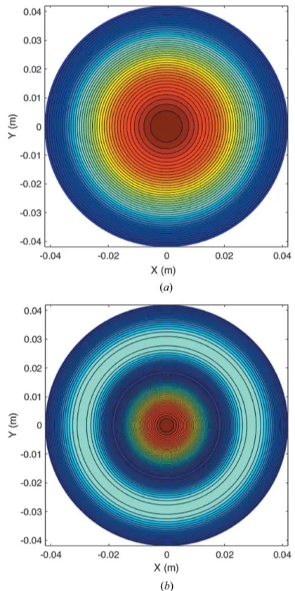
Usually, a higher order HE or EH mode is not linearly polarized. The suitable operating modes in the corrugated waveguide for the microwave undulator application are the HE11 and HE12 modes because they are low loss, linearly
polarized and have the peak electric field at the waveguide center. The electric field patterns of the HE11and HE12modes
are shown in Fig. 2. The HE12mode has larger field density at
the waveguide center. It can have a bigger electric field compared with the HE11mode at the same input power.
The attenuation coefficient defined by the ratio between the lost power and the transported power per meter for the HE1n
modes, under the balanced hybrid condition, can be written as (Clarricoats & Olver, 1984; Doane, 1985)
¼1 2 Rs Z0 x2 1k x04
1
1
kb 1þ x0
1
2
þx01
; ð9Þ
where Z0 = 1/Y0 is the free space wave impedance, Rs = (f0 )
1/2
is the resistivity of the corrugated metal waveguide and is the conductivity of the metal. In this paper, oxygen-free high-conductivity copper was chosen and = 5.8
107S m1 was used in the simulation. Equation (9) implies that the attenuation coefficient is proportional tor13andf2
in the case ofx101.
The corrugated waveguide can be shortened at both ends to form a cavity. The resonance frequency of the corrugated waveguide can be estimated as
f ¼ c
0¼
c
2 K
2
þ N
g
!2
" #1=2
; ð10Þ
where c is the speed of light, N is an integer and g is the
wavelength of the resonance mode in the cavity. Because the
Figure 1
corrugated waveguide is normally overmoded,0’gwhen N= 2. As mentioned earlier, the surface-impedance approach gives a good approximation when0/pis a reasonably large
value. Therefore, when designing the corrugated waveguide, the periodpcan be selected to be smaller than0/2. It is of
course the case that ‘the smaller the period, the better’; however, as the operating frequency increases, the wavelength becomes smaller, resulting in a small corrugation period and a thin corrugation slot ofw’0 which significantly increases the machining difficulty. The final choice of the geometry should therefore also consider the machining tolerance.
Since x01¼kr1¼2r1=01 has to be satisfied, the
corrugated waveguide radius r1 is a large value. As the attenuation coefficient is proportional tor13, it is preferable to
have a larger1at a given operating frequency. From equation
(8), the waveguide radius affects the field strength if the input power is a fixed value. In a microwave undulator, a high field at the electron beam path, in this case the waveguide center, is
desired. Thereforer1should be as small as possible under the constraint ofkr11. On the other hand, it is preferred for the electron beam that travels through the microwave undulator to see a uniform field in the radial direction. The minimum waveguide radius can be solved from the field pattern of the operating mode if the electron beam aperture Rb and a threshold, for example 90% of the maximum field at the beam edge, are defined. For HE1nmodes, it follows thatJ1(KRb) =
0.9. Taking the first two solutions of J0(Kr1) = 0, K is approximately equal to 2.4/r1 or 5.5/r1 for the HE11 or the
HE12mode, respectively. Therefore the following parameters
were chosen,
r1¼
3:8Rb; for the HE11 mode;
8:6Rb; for the HE12 mode;
resulting in a reasonable value ofr1. Meanwhile the value ofr1
should satisfyx10= 2r1/
01. Ifx10= 5 is used, thenr10.80
and the results become
r1¼ maxima 3ð :8Rb;0:80Þ; for the HE11 mode;
maxima 8ð :6Rb;0:80Þ; for the HE12 mode:
4. Design of a corrugated waveguide for an MU A corrugated waveguide cavity operating at 36 GHz was designed as a potential microwave undulator for the UK XFEL. The initial geometry parameters were calculated from the equations described in previous sections. Both of the HE11
and HE12modes are considered. A summary of the geometry
parameters as well as the undulator deflection parameter
Ku¼0:09336Buu½T mmare listed in Table 1.
[image:4.610.64.274.69.490.2]The accurate resonance frequency and Q factor of the designed structure were simulated using CST Microwave Studio. The simulated structure was set at six corrugation periods to significantly reduce the simulation time. For such a short cavity length, the loss at the conducting wall at both sides will be much larger than the loss at the corrugated wall because the field strength at the corrugated wall is much smaller. In the simulation, a periodic boundary condition was set at both ends of the corrugated waveguide. In this way, the
Figure 2
[image:4.610.314.565.92.247.2]Contour plot of the electric field patterns of the (a) HE11and (b) HE12 modes.
Table 1
Parameters of the MU composed of a corrugated waveguide.
Operating mode HE11 HE12
Operating frequency (GHz) 36 36
0(mm) 8.33 8.33
Rb(mm) 2.0 2.0
r1(mm) 4Rb= 8.0 9Rb= 18.0
d=0/4 (mm) 2.1 2.1
g(mm) 9.06 9.12
p=g/3 (mm) 3.00 3.02
w(mm) 0.5 0.5
b=pw(mm) 2.50 2.52
Qfactor 94344 187073
Input power (MW) 50 50
PeakExon axis (V m1) 3.8108 3.7108
Bu(T) 1.27 1.23
u(mm) 4.34 4.35
loss at both sides will not be included. Fig. 3 shows the electric field distribution of the cavity modes of HE114and HE124. The
peak Ex field along the z axis was obtained from the field distribution of the eigenmode and normalized to an Ohmic loss power of 50 MW at a cavity length of 1 m. With the same input power and similar operating frequency, the waveguide radius of the HE12mode was about 2.2 times that of the HE11
mode, and its Qfactor was nearly 2 times that of the HE11
mode. TheExfield strength was slightly smaller than that of the HE11 mode. The equivalent magnetic field Bu was also
similar for both cases.
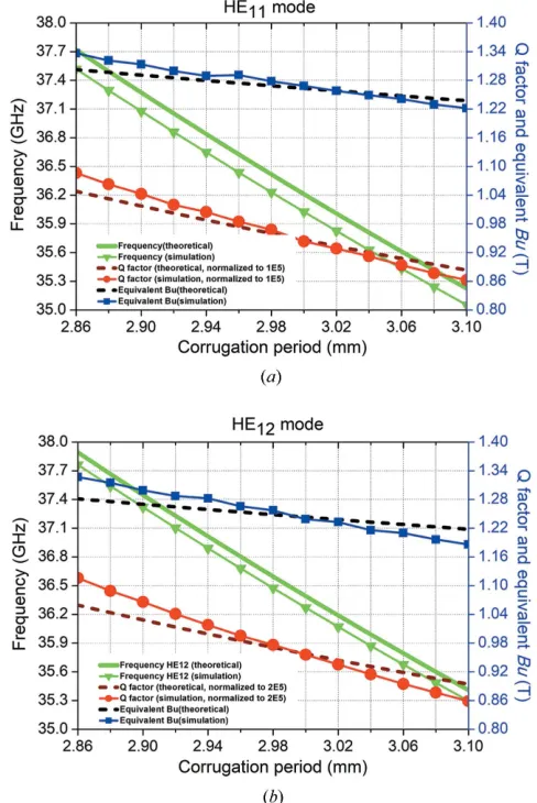
Parameter scans were used to study the effects of varying of the corrugation geometry parameters such as the corrugation period (p), the slot length (w) and the waveguide radius (r1).
The results of resonance frequency, Qfactor and equivalent magnetic field strength are shown in Figs. 4–6. The HE11mode
has a similar trend to the HE12mode. In Fig. 4, as the
corru-gation period increases, the resonance frequency becomes smaller while the slot length (w) and the waveguide radius (r1) are kept the same. The results matched the theoretical calculation well from equation (10) and the scaling law equations (Shumailet al., 2011). The difference between the simulation and theoretical calculation is less than 2%, there-fore it allows a fast prediction of the cavity parameters from the theoretical analysis. The Q factor reduces as the corru-gation period increases. It is mainly caused by the increase of the overall waveguide length and the decreases in the stored energy per unit length.
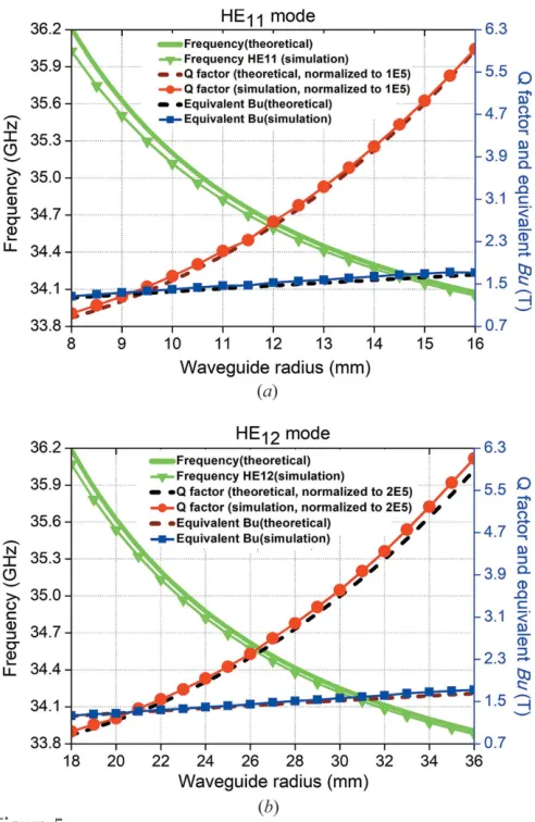
The simulation results at the different waveguide radii are shown in Fig. 5. The trends for the HE11and HE12modes are
very similar. Increasing the waveguide radius would signifi-cantly increase the Q factor and the resonance frequency drops quickly. However, from equation (4), a high Qfactor
would result in a long filling time. For the HE11mode, a 20%
increment of the waveguide radius would lead to aQfactor close to 150 000, requiring an increase in the pulse length of the high-power microwave source used to drive the structure. Also, increasing the waveguide radius did not improve the equivalent magnetic field, which was almost the same. Therefore, the designed waveguide radius was considered to be optimal.
The simulation results of the variation in slot length while keeping the corrugation period constant are shown in Fig. 6. Only the CST simulation results were included as the theo-retical analysis will not be accurate at small slot length values. As the slot length increases, the assumption of only the lowest TM standing wave appearing in the slot is no longer satisfied. The field at the corrugation wall became larger and caused a significant reduction in the cavityQ. The Qfactor dropped more quickly for the HE11mode than the HE12mode because
[image:5.610.54.289.69.318.2]its waveguide radius was smaller. As the corrugation period was kept constant, the change in the resonance frequency was small. The equivalent magnetic field Bu also changed by a small amount. The simulation results proved that the slot length should be as small as possible to achieve a high Q
Figure 4
[image:5.610.317.561.355.720.2]Simulation results of different corrugation periods: (a) HE11mode and (b) HE12mode.
Figure 3
factor. However, the difficulty in manufacturing such a struc-ture while maintaining sufficient mechanical strength needs to be taken into account. A slot length of 0.5 mm is a reasonable value to satisfy the criteria of ease of manufacture, while at the same time being mechanically strong.
5. Discussion and conclusions
In this paper, a corrugated waveguide was studied as a microwave undulator for a UK XFEL. The equations that govern the performance of the microwave undulator are presented and have been used to estimate the dimensions of the corrugated waveguide.
Both of the HE11 and HE12 modes existing in the
corru-gated waveguide are suitable operating modes. Their char-acteristics were studied using numerical simulation and their performance compared in the design of a corrugated wave-guide operating at 36 GHz. It was found that the equivalent magnetic field for both of the modes was very similar. The HE12mode had a much larger waveguide radius, which could
be advantageous for high-frequency operation because it helps to reduce the difficulty in manufacture as well as redu-cing the electric field at the wall. The HE12mode is also less
sensitive to the slot length compared with the HE11mode. The
drawback of the HE12mode includes a much higherQfactor
that leads to a longer filling time and greater sensitivity to the waveguide period.
Funding information
The authors would like to thank the Science and Technology Facilities Council (STFC) UK and the Cockcroft Institute (Core Grant ST/P002056/1) for supporting this work.
References
Alvarez, R. A. (1986).Rev. Sci. Instrum.57, 2481–2488.
Chang, C., Shumail, M., Tantawi, S., Neilson, J. & Pellegrini, C. (2012). Appl. Phys. Lett.101, 161102.
Clarricoats, P. J. B. & Olver, A. D. (1984). Corrugated Horns for Microwave Antennas,IEE Electromagnetic Waves Series, Vol. 18. Institution of Engineering and Technology.
Clarricoats, P. J. B. & Saha, P. K. (1971).Proc. Inst. Electr. Eng. UK,
118, 1177–1186.
Crenn, J. P. & Charollais, C. (1996).Int. J. Infrared Milli Waves,17, 1475–1506.
Deacon, D. A. G., Elias, L. R., Madey, J. M. J., Ramian, G. J., Schwettman, H. A. & Smith, T. I. (1977).Phys. Rev. Lett.38, 892– 894.
Doane, J. L. (1985).Infrared Millimeter Waves, Vol. 13, pp. 123–170. Orlando: Academic Press.
Dragone, C. (1980).IEEE Trans. Microw. Theory Techn.28, 704–710. Huang, Z. & Kim, K.-J. (2007).Phys. Rev. ST Accel. Beams, 10,
034801.
James, G. L. (1981).IEEE Trans. Microw. Theory Techn.29, 1059– 1066.
Kowalski, E. J., Tax, D. S., Shapiro, M. A., Sirigiri, J. R., Temkin, R. J., Bigelow, T. S. & Rasmussen, D. A. (2010).IEEE Trans. Microw. Theory Techn.58, 2772–2780.
Neilson, J. M., Latham, P. E., Caplan, M. & Lawson, W. G. (1989). IEEE Trans. Microw. Theory Techn.37, 1165–1170.
Pellegrini, C. (2006).AIP Conf. Proc.807, 30–45.
Seidel, M. (2001). TESLA-FEL 2001–08, pp. 1–14. TESLA-FEL Reports, DESY, Hamburg, Germany.
Shintake, T., Huke, K., Tanaka, J., Sato, I. & Kumabe, I. (1982).Jpn. J. Appl. Phys.21, L601–L603.
[image:6.610.48.294.68.446.2]Shintake, T., Huke, K., Tanaka, J., Sato, I. & Kumabe, I. (1983).Jpn. J. Appl. Phys.22, 844–851.
Figure 6
[image:6.610.47.293.488.658.2]Simulation results of different slot lengths. Figure 5
Shumail, M. (2014). PhD thesis, Stanford University, USA.
Shumail, M., Bowden, G. B., Chang, C., Neilson, J., Tantawi, S. G. & Pellegrini, C. (2011).Proceedings of the 2nd International Particle Accelerator Conference (IPAC 2011), 4–9 September 2011, San Sebastian, Spain, pp. 3326–3328. THPC183.
Shumail, M. & Tantawi, S. G. (2016).Phys. Rev. ST Accel. Beams,19, 074001.
Tantawi, S., Shumail, M., Neilson, J., Bowden, G., Chang, C., Hemsing, E. & Dunning, M. (2014).Phys. Rev. Lett.112, 164802.
Toufexis, F. & Tantawi, S. (2017).Proceedings of the 8th International Particle Accelerator Conference (IPAC 2017), 14–19 May 2017, Copenhagen, Denmark, pp. 1643–1646. TUPAB135.