UNIVERSITI TEKNIKAL MALAYSIA MELAKA
DESIGN MICROWAVE LINK BUDGET AND INTERFERENCE
ANALYSIS
This report submitted in accordance with requirement of the Universiti Teknikal Malaysia Melaka (UTeM) for the
Bachelor’s Degree in Electronics Engineering Technology (Telecommunications) (Hons.)
by
NURUL AMALIN BINTI MOHAMAD RAZALI
B071110214
920218035938
UNIVERSITI TEKNIKAL MALAYSIA MELAKA
BORANG PENGESAHAN STATUS LAPORAN PROJEK SARJANA MUDA
TAJUK: Design Microwave Link Budget and Interference Analysis
SESI PENGAJIAN: 2014/15 Semester 2
Saya NURUL AMALIN BINTI MOHAMAD RAZALI
mengaku membenarkan Laporan PSM ini disimpan di Perpustakaan Universiti Teknikal Malaysia Melaka (UTeM) dengan syarat-syarat kegunaan seperti berikut: 1. Laporan PSM adalah hak milik Universiti Teknikal Malaysia Melaka dan penulis. 2. Perpustakaan Universiti Teknikal Malaysia Melaka dibenarkan membuat salinan
untuk tujuan pengajian sahaja dengan izin penulis.
3. Perpustakaan dibenarkan membuat salinan laporan PSM ini sebagai bahan pertukaran antara institusi pengajian tinggi.
4. **Sila tandakan ( )
SULIT
TERHAD
TIDAK TERHAD
(Mengandungi maklumat yang berdarjah keselamatan atau kepentingan Malaysia sebagaimana yang termaktub dalam AKTA RAHSIA RASMI 1972)
(Mengandungi maklumat TERHAD yang telah ditentukan oleh organisasi/badan di mana penyelidikan dijalankan)
Alamat Tetap:
PT 759 TAMAN PERMAI DEMIT KUBANG KERIAN, KOTA BHARU KELANTAN
Tarikh: 14 JANUARI 2015
Disahkan oleh:
Cop Rasmi:
Tarikh: _______________________
FAKULTI TEKNOLOGI KEJURUTERAAN
Tel : +606 234 6623 | Faks : +606 23406526
Rujukan Kami (Our Ref) : Rujukan Tuan (Your Ref) :
01 JAN 2015
Pustakawan
Perpustakaan UTeM
Universiti Teknikal Malaysia Melaka Hang Tuah Jaya,
76100 Durian Tunggal, Melaka.
Tuan/Puan,
PENGKELASAN LAPORAN PSM SEBAGAI SULIT/TERHAD LAPORAN PROJEK SARJANA MUDA TEKNOLOGI KEJURUTERAAN PEMBUATAN (COURSE NAME): AAA BIN BBB
Sukacita dimaklumkan bahawa Laporan PSM yang tersebut di atas bertajuk
“Development of Integrated Failure Mode And Effect Analysis (l-FMEA)
For Automotive Industry” mohon dikelaskan sebagai *SULIT / TERHAD untuk tempoh LIMA (5) tahun dari tarikh surat ini.
2. Hal ini adalah kerana IANYA MERUPAKAN PROJEK YANG DITAJA OLEH SYARIKAT LUAR DAN HASIL KAJIANNYA ADALAH SULIT.
Sekian dimaklumkan. Terima kasih.
Yang benar,
________________
Tandatangan dan Cop Penyelia
* Potong yang tidak berkenaan
DECLARATION
I hereby, declared this report entitled “Design Microwave Link Budget and Interference Analysis” is the results of my own research except as cited in
references.
Signature : ……….
Author’s Name : NURUL AMALIN BINTI MOHAMAD RAZALI
Date : 12 DECEMBER 2014
APPROVAL
This report is submitted to the Faculty of Engineering Technology of UTeM as a partial fulfillment of the requirements for the degree of Bachelor of Engineering Technology (Electronic (Telecommunication)) (Hons.). The member of the supervisory is as follow:
……… (Project Supervisor)
ABSTRAK
Permintaan yang semakin meningkat dalam data komunikasi menyebabkan
pembangunan kaedah inovatif untuk memenuhi keperluan komunikasi semasa dan
baru. Kejuruteraan pautan radio bermula dengan melakukan analisis bajet pautan.
Sistem radio yang diberikan mempunyai peningkatan sistem yang bergantung kepada
reka bentuk radio dan modulasi yang digunakan. Antena yang lebih besar
memberikan kadar peningkatan yang lebih tinggi. Kawasan yang luas dan bebas
digunakan untuk menentukan semakin tinggi jarak kawasan semakin rendah kadar
kehilangan. Gelombang mikro adalah salah satu bentuk radiasi elektromagnetik
dengan panjang gelombang yang setara, dengan frekuensi antara 300 MHz dan 300
GHz . Ini juga melibatkan pengiraan peningkatan dan penurunan yang berkaitan
dengan antena , pemancar dan penghantaran talian iaitu untuk menentukan jarak
maksimum di mana sebuah pemancar dan penerima boleh beroperasi . Dalam kajian
kes , ia akan memberi tumpuan kepada mengurangkan gangguan . Gangguan dalam
komunikasi dan elektronik terutamanya dalam telekomunikasi adalah apa-apa yang
mengubah , diubah suai atau mengganggu isyarat yang bergerak di sepanjang saluran
antara sumber dan penerima. Semakin rendah nilai gangguan atau bunyi yang
diandaikan dengan nilai yang terhad , lebih rendah nilai gangguan . Oleh itu , bajet
pautan gelombang mikro yang menggunakan GUI akan memudahkan lagi untuk
mengira jarak maksimum antara dua menara iaitu menara pemancar, TX dan menara
penerima, RX berdasarkan latitud dan longitud dengan nilai yang terhad. Semakin
tinggi jarak antara TX dan RX, semakin rendah nilai penerimaan kuasa dan lebih
mudah untuk mengira dan mengurangkan gangguan dengan nilai yang terhad dengan
bunyi yang digunakan .
ABSTRACT
The increasing demand for data communications and connectivity has resulted in the development of innovative methods to satisfy current and emerging communication requirements. Radio link engineering begins by doing a link budget analysis. A given radio system has a system gain that depends on the design of the radio and the modulation used. The gains from antenna at each end are added to this gain. The free-space loss of the radio signal as it travels over the air is then subtracted from the system which is the longer the link the higher the loss. Microwaves are a form of electromagnetic radiation with wavelengths which is equivalently, with frequencies between 300 MHz and 300 GHz. This is also calculation involving the gain and loss factors associated with the antennas, transmitters and transmission line which is to determine the maximum distance at which a transmitter and receiver can successfully operate. In case study, it will focus on the reducing interference. Interference in communications and electronics especially in telecommunication is anything which alters, modified or disrupts a signal as it travels along a channel between a source and a receiver. The lower the value of interference or noise that assumed with the limited value, the lower the value of reducing interference. Hence, microwave link budget that used the GUI will easier to calculate the maximum distance between two towers which is transmitter tower, TX and receiver tower, RX based on latitude and longitude with the limited value of input parameters. The longer the distance between TX and RX the lower the value of receive power and the higher the value of path loss Also, easier to calculate the reduce interference with the limited value of noise that used.
DEDICATION
This thesis is dedicated to my family and many friends. A special feeling of gratitude to my loving parents, En.Mohamad Razali Bin Abdullah and Pn.Rosnimi Binti Hj. Alias whose words of encouragement and push for tenacity ring in my ears. My brothers and sister Shafiq, Shahril and Nurul Amira have never left my side and are very special.
I also dedicated this dissertation to my many friends who supported me through the process. I will always appreciate all they have done, especially Nur Hafialia for helping me develop my technology skills, Nur Amira for the many hours of proofreading, and Liana Anak Crocker for helping me to master the leader dots.
I dedicate this work and give special thanks to my best friend Siti Nur Fatihah and Rosnida for being there for me through the entire doctorate project. Both of you have my best cheerleaders.
ACKNOWLEDGEMENT
I would like to express my sincere thanks and appreciation to my supervisors, Mr. Abdul Halim Bin Dahalan from Faculty Engineering Technology Universiti Teknikal Malaysia Melaka (UTeM) who has given me this bright opportunity to engage in microwave link budget design and interference analysis project. It is my first step to establish a career in GUI design field. A million thanks to you.
I would also like to express my greatest gratitude to Mr. Mohamad Zoinol Abidin Bin Abd. Aziz from Faculty of Electronic and Computer Engineering, co-supervisor of this project for his advice and suggestions in microwave link.
Particularly, I would also like to express my greatest gratitude to Engr. Ahmad Fauzan Bin Kadmin and Mr. Chairulsyah Wasli from Faculty Engineering Technology, the lecturers for their assiatance and efforts in all the analysis of this project. Lastly, thank you to everyone who had been to the crucial parts of realization in completing this degree’s project.
TABLE OF CONTENT
Abstrak i
Abstract ii Dedication iii
Acknowledgement iv Table of Content v List of Tables vi
List of Figures vii List Abbreviations, Symbols and Nomenclatures viii
CHAPTER 1: INTRODUCTION 1
1.1 Background 1
1.1.1 Radio Link 1
1.1.2 Interference Analysis 2
1.1.3 Microwave Radio Frequency 6
1.1.4 Graphical User Interface (GUI) 6
1.2 Problem Statement 7
1.3 Objectives 8
1.4 Scope of Project 8
CHAPTER 2: LITERATURE REVIEW 9
2.1 Link Budget Analysis 9
2.1.1 Radio Link 9
2.1.2 Calculation of Link Budget 11
2.1.3 Microwave Link 14
2.2 Geographical Distance Based on Latitude and Longitude 16
2.2.1 Coordinate System 16
2.2.2 Database 17 CHAPTER 3: METHODOLOGY 19
3.1 Literature Survey 20
3.2 Data Collection 20
3.3 Simulation Design 21
3.3.1 Insert Base Station Image and UTeM’s Logo 22
3.3.2 Build Map 25
3.3.3 Build Base Station Location 27
3.3.4 Calculate for Output Parameter 30 3.3.5 Insert Country in Map 33 3.3.6 Vertical and Horizontal Map Move 35
3.3.7 Zoom In and Zoom Out of Map 37 3.3.8 Reset in Map 39
3.3.9 Exit GUI 41 CHAPTER 4: RESULT & DISCUSSION 43
4.1 Result 43
4.1.1 Input GUI 43 4.1.2 Output GUI 44
4.1.3 Simulation Process 45
4.2 Discussion 46 4.2.1 Maximum Distance between Transmitter and Receiver 46 4.2.2 Reducing Interference 52
CHAPTER 5: CONCLUSION & RECOMMENDATION 53
5.1 Conclusion 53
5.2 Recommendation 55
REFERENCES 56
APPENDICES 57
A List of Respondents
LIST OF TABLES
1.1 RF Microwave 6
2.1 Form of Database 18
LIST OF FIGURES
1.1a Wireless Communication Link 2
21.1b Spectrum Environment 3
1.1c Interference from GSM 4
1.1d Interference on Wireless Communication Link 5
1.1e GUI started. 7
2.1 Satellite Top View of the University of Birmingham Campus Ground Profile. 11
2.2a Locations and field-of-view of the four GPS station adopted. 17
2.2b Branches and Azimuth of Branches 18
3.1 Flow Chart 19
3.3a Simulation Design 21
3.3b Image of Base Station 22
3.3c Logo UTeM 23
3.3d Flow Chart of Logo/Image 24
3.3e Map 25
3.3f Flow Chart of Map 26
3.3g Base Station Pushbutton1 27
3.3h Base Station Location in the Map 27
3.3i Flow Chart of Base Station Location 29
3.3j Calculate Pushbutton10 30
3.3k Input of Parameter 30
3.3l Output Parameter 31
3.3m Flow Chart of Parameter 32
3.3n Country Pushbutton9 33
3.3o Country Map 33
3.3p Flow Chart of Country 34
3.3q Move Pushbutton4 and Pushbutton5 35
3.3r Flow Chart Move 36
3.3s Zoom In & Zoom Out Pushbutton6 and Pushbutton7 37
3.3t Flow Chart Zoom In & Out 38
3.3u Reset Pushbutton2 39
3.3v Flow Chart Reset 40
3.3w Exit Pushbutton3 41
3.3x Flow Chart Exit 42
4.1a Input GUI 43
4.1b Output GUI 44
4.1c Flow Chart Simulation Process 45
4.2a Example to Calculate Receive Power, Pr 50
4.2b Short Distance between TX and RX 50
4.2c Long Distance between TX and RX 51
LIST OF ABBREVIATIONS, SYMBOLS AND
NOMENCLATURE
RF - Radio Frequency
GSM - Global System for Mobile
WCDMA - Wideband Code Division Multiple Access LTE - Long-Term Evolution
UHF - Ultra High Frequency EHF - Extremely High Frequency SHF - Super High Frequency GUI - Graphical User Interface EIRP - Isotropic Radiated Power
MS - Mobile Station
BTS - Base Transceiver Station RFID - Radio Frequency Identification
NASA - National Aeronautics and Space Administration TRMM - Tropical Rainfall Measuring Mission's
IEEE - Institute of Electrical and Electronics Engineers DSD - Drop Size Distribution
GPS - Global Positioning System
GNSS - Global Navigation Satellite System
1.1 Background
1.1.1 Radio Link
The increasing demand for data communications and connectivity has resulted in the development of innovative methods to satisfy current and emerging communication requirements. The path on which data travels from its source to its destination is described as a communications link.
Radio link engineering begins by doing a link budget analysis. A given radio system has a system gain that depends on the design of the radio and the modulation used. The gains from antenna at each end are added to this gain. Larger antennas provide higher gain. The free-space loss of the radio signal as it travels over the air is then subtracted from the system which is the longer the link the higher the loss.
INTRODUCTION
CHAPTER 1
Figure 1.1a: Wireless Communication Link
The accounting of all the gains and losses from the transmitter through the medium such as free space, cable, waveguide, fiber et cetera to the receiver in telecommunication system is known as link budget. To specify power, frequency and antenna requirements the principle of data link design is needed to ensure the reliable conveyance of data across the wireless data link, while accounting for the effects of attenuation, propagation, and noise relating to the free-space transmission segment, as illustrated in Figure 1.1a.
The operating frequency of the link, the output power, and antenna parameters is included of the principle link parameters. Besides that, by increasing the output power levels can reduce certain aspect of wireless link interference but it can cause unnecessary interference to other electronic and communication system, and is not practical for mobile device with power source.
1.1.2 Interference Analysis
It is negatively affects of signal interference in wireless networks in transmission coverage mobile capacity, limiting overall network performance. This is becoming more prevalent of unavoidable signal in wireless networks with the increasing number of active transmitters on the RF spectrum.
Figure 1.1b: Spectrum Environment
Interference analysis has three main stages,which is detection, identification, and location. First stage of the interference analysis is the detection. It is the most commonly used test method to detect interference in spectrum analysis, which performs measurements on frequency domain. This also indicates the amount of energy or power transmitted at each frequency.
Interference identification is the second stage of the interference analysis. it is to identify the type of signal of the interference that will consederably expedite troubleshooting. For example, it is common for a cell site to support multiple technologies such as GSM, WCDMA, and LTE. Some users use mobile devices primarily for voice communication supported by GSM.
Figure 1.1c: Interference from GSM
Last stage of the interference analysis is the interference location. After an interferer signal has been detected, its transmission frequency obtined, and signal analysis performed for its identification, the next step is to obtain the geographical location of the interferer. It is normally requested to cease its transmission, generally by giving a warning or proceeding legally against the interferer at the interferer location.
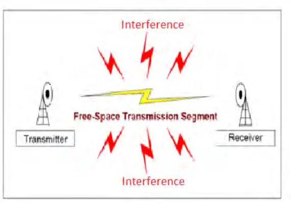
Figure 1.1d: Interference on Wireless Communication Link
Electronic interference is the condition of electromagnetic energy distrupting the normal operation or function of electronic devices. The source of the electronic interference can be categorized as environmenal or naturally accurring, incidental or intentional. Interference is present at all frequencies, vary according to a specific frequency band, and affect the speed, accurancy and range of communication. Interference also known as unwanted interaction between electronic systems.
However, the primary sources of interference that effect wireless communication systems are electromagnetic in nature and can result in the magnetic and radio frequency disruption or intermittent failure of electronic, communication and information systems.
The inherent physical, technical and mechanical design parameters associated with wired data links for example fiber optic or cable often offer a level of immunity from noise and interference sources. In addition, wired media has certain attributes that can limit the effect of noise and interference which adversely affect wireless data links.
1.1.3 Microwave Radio Frequency
Table 1.1: RF Microwave
The microwaves radio frequency are a form of electromagnetic radiation with wavelengths , or equivalently, with frequencies between 300 MHz and 300 GHz. This broad definition includes both ultra high frequency (UHF) and extremly high frequency (EHF) and various sources use different boundaries. In all cases, microwave includes the entire SHF band, with RF engineering often putting the lower boundary at 1 GHz and the upper around 100.
1.1.4 Graphical User Interface (GUI)
GUI also known as graphical user interference that provides point-and-click control of software applications, eliminating the need to learn a language or type commands in order to run the application.
Figure 1.1e: GUI started.
MATLAB apps are self-contained MATLAB programs with GUI front ends that automate a task or calculation. The GUI typically contains controls such as menus, toolbars, buttons, and sliders.
GUIDE which is graphical user interface design environment provides tools for designing user interfaces for custom apps. GUIDE then automatically generates the MATLAB code for constructing the UI.
1.2 Problem Statement
Determine the maximum distance at which a transmitter and receiver can operate. Besides that, interference that effect wireless communication systems are electromagnetic in nature and can result in the magnetic and radio frequency disruption or intermittent failure of electronic, communication and information systems.
1.3 Objectives
The objective of this project is to reduce the interference and to design the simulation of microwave link budget that can be easily to determine the maximum distance of transmitter and receiver.
1.4 Scope of Project
There is a few scope of this research project, it will
include:-i. Study the effect of frequency interference.
ii. Study the radio frequency (RF) of the microwave link budget. iii. Design the simulation base on link budget.
iv. Design the simulation of reducing the frequency interference.
2.1 Link Budget Analysis
The calculation that involving the gain and loss factors associated with the antennas, transmitters, transmission lines and propagation environment which is to determine the maximum distance at which a transmitter and receiver can successfully operation known as link budget. Radio frequency of microwave is start from 300 MHz and goes up to 300 GHz that have wavelength of 1m to 0.01 m. Hence, for the interference is the signal in wireless networks negatively affects transmission coverage and mobile capacity that limiting overall network performance.
2.1.1 Radio Link
The free band beyond 300 GHz of communication systems are of interest for short distance communication. The realistic link budget analysis is needed to assess the feasibility of such a communication system. For the link budget analysis it focused on the measurement of transmission losses using all electronic Tx-Rx system that operating from 325 to 500 GHz.