DESIGN AND DEVELOPMENT OF BANDPASS FILTER BASED ON HIGH Q
CAVITY FILTER STRUCTURES FOR MICROWAVE IMAGING
TECHNOLOGY
FATIN FARHANA BINTI MOHD RASHID
This Report Is Submitted In Partial Fulfilment Of Requirements For The Bachelor Degree of
Electronic and Computer Engineering (Wireless Communication) with Honours
Fakulti Kejuruteraan Elektronik dan Kejuruteraan Komputer
Universiti Teknikal Malaysia Melaka
Tajuk Projek
Sesi Pengajian
UNIVERSTI TEKNIKAL MALAYSIA MELAKA
F AKUL Tl KEJURUTERAAN ELEKTRONIK DAN KEJURUTERAAN KOMPUTER BORANGPENGESAHANSTATUSLAPORAN
PROJEK SARJANA MUDA II
DESIGN AND DEVELOPMENT OF BANDPASS FILTER BASED ON HIGH Q CAVITY FILTER STRUCTURES FOR MICROWAVE IMAGING TECHNOLOGY
Sa ya FA TIN F ARHANA BINTI MOHD RASHID
(HURUF BESAR)
mengaku membenarkan Laporan Projek Sarjana Muda ini disimpan di Perpustakaan dengan syarat-syarat kegunaan seperti berikut:
1. Laporan adalah hakmilik Universiti Teknikal Malaysia Melaka.
2. Perpustakaan dibenarkan membuat salinan untuk tujuan pengajian sahaja.
3. Perpustakaan dibenarkan membuat salinan laporan ini sebagai bahan pertukaran antara institusi pengajian tinggi.
4. Sila tandakan ( '1 ) :
D
SULIT*D
TERHAD**[lZf
TIDAK TERHAD
(T-Tarikh: .... 7_1.lJ]\I_ ~O_l: ... .. .
*(Mengandungi maklumat yang berdarjah keselamatan atau kepentingan Malaysia seperti yang termaktub di dalam
AKTA RAHSIA RASMI 1972)
**(Mengandungi maklumat terhad yang telah ditentukan oleh
111
"I hereby declare that this thesis is my original work and it has been written by
myself in its entirely. I have duly acknowledged all of the sources and writings which
Signature
Author
Date
: Fatin Farhip1a binti Mohd Rashid
lV
"I acknowledge that I have read this thesis and in my opinion this thesis was sufficient in terms of scope and quality for the certification of the degree of Bachelor
of Electronic Engineering (Wirele Communication) with Honours"
Signature
Supervisor's Name
Date
: PM. Dr Badrul Hisham bin Ahmad
: 7th June 2017
Prof. MttLi - _,. _, 1 :;ham Bin Ahmad ~fO,{'~ or,; 1c;aya
Fakulti Kejuruteraan Elektronlk an Kejuruteraan Komputer
Universiti Teicnilr.al Malaysia Melaka (UTeM)
Hang Tu3h Jaya
v
vi
ACKNOWLEDGMENT
My deepest gratitude goes first to PM Dr. Badrul Hisham bin Ahmad, an Associate Professor in Universiti Teknikal Malaysia Melaka and also my final year project’s supervisor, who expertly guided me through my journey to complete my final year project for the past two semesters. His unwavering enthusiasm for radio frequency subject had kept me constantly engaged with my project, and his personal generosity helped make my time doing the project enjoyable.
My appreciation also extends to the lecturers and staffs of Faculty of Electronic and Computer Engineering (FKEKK) for helping and guiding me around the laboratories and using the laboratory equipment. Not to be forgotten, all my 4-BENW friends who are walking this journey together with me and showering with me supports, help and guidance. Thank you for being the best friends who are willingly to go through thick and thin together until the end of final year project.
vii
ABSTRACT
Microwave system is the new emerging technology that had shown a vast impact towards the modern generations due to the development and advanced microwave technology. The microwave technology is like the open door to the future where there are a massive potential regarding the radio frequencies applications. In order to accomplished this advanced technology, the design of high performance bandpass filter is very important. Filters are one of the most important component in microwave application that are used to discriminate between desired and undesired frequencies in devices. They have played the main key to distinguish the devices in term of devices’ performance and cost especially in the congested spectrum. Therefore, this thesis presents the design and development of bandpass filter based on high Q cavity filter structures for microwave imaging technology. The filter will provide high frequency selectivity and low insertion loss that will be the main criteria for high Q filter design which results in high performance. The design process is designed by the lossless Chebyshev lowpass prototype and followed by the transformation of the lowpass prototype to rectangular waveguide cavity bandpass filter. The simulation with the aid of EM Simulator will be tuned in order to obtain the desired design specification. Besides, the filter is designed with smaller size despite the high number of resonators. This will lead a design of bandpass filter with high performance. Since the design provides a high performance bandpass filter, it is great in for the use of microwave imaging technology.
viii
ABSTRAK
ix
TABLE OF CONTENT
TITLE APPROVAL DECLARATION DEDICATION ACKNOWLEDGEMENT ABSTRACT ABSTRAK
TABLE OF CONTENT LIST OF TABLE LIST OF FIGURE LIST OF SYMBOL
CHAPTER 1-INTRODUCTION
1.1 Summary of the Project 1.2 Problem Statement 1.3 Objectives
1.4 Scope of Project 1.5 Project methodology
1.5.1 Literature Outline
1.5.2 Calculation and Design of the Bandpass Filter 1.5.3 Simulation
1.5.4 Fabrication of the Final Design 1.6 Thesis Outlines
xi
CHAPTER 2-LITERATURE REVIEW
2.0 Microwave Spectrum
2.1 Microwave Imaging Technology 2.2 Microwave Filters
2.3 Filter Design
2.3.1 Prototype Low-pass Design by Insertion Loss Method
2.3.1.1 Butterworth Prototype Response 2.3.1.2 The Chebyshev Prototype Response 2.4 Microwave Low-pass Filter
2.5 Microwave High-pass Filter 2.6 Microwave Band-pass Filter 2.7 Transmission Lines
2.7.1 General Solution for TEM, TE and TM Waves 2.7.1.1 TEM Wave
2.7.1.2 TE Mode 2.7.1.3 TM Waves 2.7.2 Strip Transmission Lines 2.7.3 Microstrip Transmission Lines 2.7.4 Waveguide as Transmission Line 2.8 Fundamental of Rectangular Waveguide
2.8.1 Propagation Modes in Rectangular Waveguide 2.8.1.1 TE Mode in Rectangular Waveguide 2.8.1.2 TM Mode in Rectangular Waveguide 2.9 Design of Waveguide Bandpass Filter
CHAPTER 3-METHODOLOGY
3.1 Rectangular Waveguide Band-pass Filter Specification 3.2 The Chebyshev Prototype
3.3 Transmission from Lowpass to Bandpass Transformation
xii
3.4 Simulation Design of Rectangular Waveguide Cavity Bandpass Filter
3.4.1 Rectangular Waveguide without Post
3.4.2 Rectangular Waveguide with Cylindrical Post
CHAPTER 4-RESULT AND DISCUSSION
4.1 Rectangular Waveguide Cavity Bandpass Filter 4.2 Rectangular Waveguide Cavity Filter after Tuning 4.3 Analysis of the Result
4.3.1 Relationship of Susceptances Values (B) of Simulated Design between the Lengths of Rectangular Waveguide (mm)
4.3.2 Relationship of the Susceptances Values (B) of Simulated Design and Distance between Posts and theWall of Rectangular Waveguide (mm)
CHAPTER 5-CONCLUSION AND FUTURE WORK
5.1 Conclusion 5.2 Future Works
52
54 55
59 60
65
66
xiii
LIST OF TABLE
NO TITLE
1.1 Design specification
3.0 Standard rectangular waveguide data
3.1 Design specification for rectangular waveguide 3.2 Element values of Lowpass Prototype
3.3 Scaling element values of Lowpass Prototype
3.4 Element of rectangular waveguide cavity bandpass filter 3.5 EM simulator command design for rectangular
waveguide
3.6 Comparison between design specification and the simulated result before tuning
4.1 Comparison between design specification and the simulated result after tuning
PAGE 4 42 42 45 45 46 49 52
57
xiv
LIST OF FIGURE
NO TITLE
1.1 Project methodology flow chart 2.1 Microwave spectrum
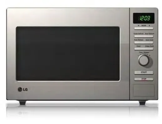
2.2 One of the application of microwave; microwave oven 2.3 3D configuration on detecting corrosion in the cement 2.4 Microwave imaging system
2.5 Hardware and software of Microwave Imaging 2.6 Microwave tomography test for medical use
2.7 Butterworth and Chebyshev insertion loss response 2.8 Prototype low-pass filter
2.9 Butterworth filter response 2.10 Chebyshev response graph 2.11 T-section of high-pass filter 2.12 π – section of high-pass filter 2.13 Band-pass filter frequency response 2.14 Equivalent circuit of a transmission line 2.15 Strip line transmission line
2.16 Microstrip transmission line 2.17 Microstrip circuit
2.18 Example of Waveguide 2.19 End view of TE10
2.20 Side view of TE10
2.21 Top view of TE10
2.22 End view of TM11
2.23 Side view of TM11
xv
2.24 Rectangular waveguide Band-pass filter
3.1 The layout of the rectangular waveguide bandpass filter 3.2 The first post becomes a reference point
3.3 Perspective view of rectangular waveguide cavity bandpass filter
3.4 Wave propagation of the rectangular waveguide cavity bandpass filter
3.5 Top view of the rectangular waveguide cavity bandpass filter with wave propagation
3.6 Graph of rectangular waveguide cavity bandpass filter 3.7 Structure of rectangular waveguide cavity bandpass filter 4.1 The structure of rectangular waveguide cavity bandpass
filter before optimization
4.2 Simulation result of rectangular waveguide cavity bandpass filter
4.3 Simulation result of rectangular waveguide bandpass filter after tuning
4.4 Simulation result of rectangular waveguide cavity bandpass filter with over-coupled result
4.5 Simulation result of rectangular waveguide cavity bandpass filter final tuning
4.6 Insertion loss, S21 rectangular cavity bandpass filter
4.7 S11 ripple curve
4.8 Relationship of susceptances of the simulated design (B) between the lengths of rectangular waveguide (mm) 4.9 Relationship between susceptances of simulated design
(B) and distance between posts and the wall (mm)
xvi
LIST OF SYMBOL
𝜔 𝜔𝐶 𝜆𝑔1 𝜆𝑔2 𝜆𝑔0 𝑓0 𝑓𝑐 𝑐 a b l 𝐿𝐴 𝐿𝑅 N S 𝜀 𝛼 K Z B 𝜓 C L r
Angular frequency of passband frequency Angular frequency of cut-off frequency Guide wavelength at lower frequency Guide wavelength at upper frequency Center guide wavelength
Center frequency Cut-off frequency Speed of light Waveguide width Waveguide height Waveguide length Stopband insertion loss Passband return loss
Degree of Chebyshev / Number of stages Ratio of stopband to passband frequencies Ripple level
Attenuation constant
CHAPTER 1
INTRODUCTION
This chapter will explain about the overview project of design and development of bandpass filter based on high Q cavity filter structures for microwave imaging technology. This chapter will cover the summary of the project, objectives, and problem statements. Project scope and project methodology that will be implemented throughout the project until it successfully done.
1.1 Summary of the project
2
This project will propose a 3D waveguide cavity bandpass filter from the High Frequency Electromagnetic Simulation (EM Simulator) software and in spectrum analyzer. The proposed microwave filter will operate at 5.0 GHz frequency with 200 MHz bandwidth. In order to design an efficient and high performance bandpass filter for microwave imaging application, a very selective bandpass response and a very low insertion loss at the passband must be achieved. From the studies of the literature review, the rectangular waveguide filter will provide both high frequency selectivity and low insertion loss where the bandpass filter will allow specific frequencies and reject unwanted frequencies. Having high selectivity frequencies and very low insertion are the main criteria for high Q cavity structure. For this various reasons, we proposed the rectangular waveguide filter for microwave imaging based on high Q cavity structures.
Nevertheless, high performance specification of bandpass filter by using conventional lumped element or planar technologies are very high to produce. Therefore, a 3D waveguide filter is proposed. This will design with the help of EM Simulator software and the simulation result will be analyzed and presented in order to get the most efficient design for the waveguide filter.
1.2 Problem Statement
Waveguide filters, microstrip filters and strip-line filters are widely used in the microwave technologies for many years. Thus, with this increasing usage of these technology, the demand from the market for an efficient and high performance bandpass filter especially in microwave imaging technology has been rising. Therefore, the bandpass filter should have the design of filter that has high frequencies selectivity and low insertion loss.
3
performance. Therefore, among all the filter designs, waveguide filter is the most likely to achieve all the high performance specifications for the modern market. However, despites all the advantages, a waveguide filter has one disadvantage which is its size is larger than any other filter design.
Since it is very difficult for the market to achieve a high performance bandpass filter design, a bandpass filter based on high Q cavity filter structure is proposed to overcome the problem by having high selectivity frequencies and low insertion loss. This specifications will be result in high Q factor.
1.3 Objectives
The objectives for the design and development of Bandpass filter based on High Q Cavity structures for Microwave Imaging are:
1) To design and development Bandpass Filter based on high Q cavity filter structure through simulation using EM simulator software.
1.4 Scope of Project
4
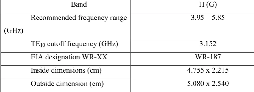
Table 1.1 Design specification
Band H (G)
Recommended frequency range (GHz)
3.95 – 5.85
TE10 cutoff frequency (GHz) 3.152
EIA designation WR-XX WR-187
Inside dimensions (cm) 4.755 x 2.215
Outside dimension (cm) 5.080 x 2.540
From the table above, the final design of the bandpass filter based on the high Q cavity filter needs to meet all the design specification in order to achieve an efficient and high performance bandpass filter.
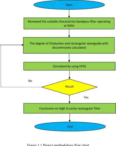
1.5 Project Methodology
5
Figure 1.1 Project methodology flow chart
1.5.1 Literature Outline
Beginning of this project, we will do a whole literature study on the title; design and development of the bandpass filter based on high Q cavity filter for Microwave Imaging and understand thoroughly on the project. This literature study involves on the findings and understanding of the background knowledge, project concept, and all related calculations for the waveguide cavity filter to be designed
Start
Reviewed the suitable characterisic bandpass filter operating at 5GHz
The degree of Chebyshev and rectangular waveguide with discontinuties calculated
Conclusion on High Q cavity rectangular filter Result
Simulated by using HFSS
End No
6
in the EM Simulator software. All the literature studies are retrieved from various information that can be obtained from books, journals, websites and calculations.
1.5.2 Calculation and Design of the Bandpass Filter
The calculation for the bandpass filter is obtain from the book study and implement into the design to achieve the specification for an efficient and high performance bandpass filter. The best approximation calculation to the specification is chose. Early design is sketched on the paper and all the parameters will be obtained before proceeding the design to EM Simulator software to obtain the simulation.
1.5.3 Simulation
The designs are then simulated by using the EM Simulator software until the most efficient and the highest performance bandpass filter is achieved. The bandpass filter will be simulated into three different parts which are the
1.5.4 Fabrication of the Final Design
After the final design has achieved the design specification, the design will be fabricated after the EM Simulator design is converted to Autocad design. Then, a measurement test will be made at the lab to compare the measurement result with the simulation result.
1.6 Thesis Outlines
7
Chapter 4 is the Result and Discussion and last but not least, Chapter 5, Conclusion and Future Work.
Chapter 1 which is the introduction n will include the overview of the project, problem statement, objectives of the project, scope of project and project methodology. As for Chapter 2, the chapter will explain in detail regarding to the project title in term of theories and concepts. For Chapter 3, the chapter will explain the design method used in the project based on the best method and theoretical formulas founds from the literature review. Besides, Chapter 4 will consists of the discussion of the results as well as detailed results from simulation and also
CHAPTER 2
LITERATURE REVIEW
This chapter will cover all the theoretical and concept of that related to the bandpass filter based on high Q cavity structures for microwave imaging. This includes the microwave imaging concept, filter response, high pass filter, low pass filter, bandpass filter, high Q factor, fundamental of waveguide, propagation mode in waveguide, discontinuities concept in waveguide filter and the design method of waveguide cavity using the Chebshey method.
2.0 Microwave Spectrum
Microwave is a form of electromagnetic wave that covers the behavior of alternating current ranging from 100MHz to 1000GHz frequencies. This frequencies are then categorized into different level of frequencies, from high frequency to ultra-high frequency. However, in term of microwave, the preferable frequencies ranging from 30 to 300 GHz, and this correspond with electrical wavelength between λ = c/f = 1o cm and λ = 1 mm, respectively [1]. A standard circuit theory often cannot be used directly to solve microwave network problems due to the fact that, generally the lumped circuit element approximation of circuit is not valid at high radio frequency
9
Figure 2.1 Microwave spectrum
As for microwave components, it is often act as distributed elements. This is caused of the phase of current or voltage changes drastically over the physical extent of the device due to device dimensions are on the order of the electrical wavelength. In other word, lower frequencies of microwave, the wavelength become large enough that there is insignificant phase variation across the device dimensions.
[image:24.595.187.446.493.691.2]