This is a repository copy of Characterisation of creep behaviour using the power law model in copper alloy.
White Rose Research Online URL for this paper: http://eprints.whiterose.ac.uk/120898/
Version: Accepted Version
Article:
Ahmad, M.I.M., Curiel-Sosa, J.L. orcid.org/0000-0003-4437-1439 and Rongong, J. (2017) Characterisation of creep behaviour using the power law model in copper alloy. Journal of Mechanical Engineering and Sciences, 11 (1). 9. pp. 2503-2510. ISSN 2289-4659
10.15282/jmes.11.1.2017.9.0230
[email protected] https://eprints.whiterose.ac.uk/ Reuse
Unless indicated otherwise, fulltext items are protected by copyright with all rights reserved. The copyright exception in section 29 of the Copyright, Designs and Patents Act 1988 allows the making of a single copy solely for the purpose of non-commercial research or private study within the limits of fair dealing. The publisher or other rights-holder may allow further reproduction and re-use of this version - refer to the White Rose Research Online record for this item. Where records identify the publisher as the copyright holder, users can verify any specific terms of use on the publisher’s website.
Takedown
If you consider content in White Rose Research Online to be in breach of UK law, please notify us by
CHARACTERIZATION OF CREEP BEHAVIOUR USING POWER LAW MODEL IN COPPER ALLOY
M.I.M Ahmad1, 2*, J.L. Curiel Sosa1 and J.A Rongong1
1
Department of Mechanical Engineering, The University of Sheffield, Sir Frederick Mappin Building, Mappin Street, S1 3JD Sheffield, United Kingdom
*Email: [email protected]
2
Department of Mechanical & Materials Engineering, Faculty of Engineering and Build Environments, Universiti Kebangsaan Malaysia, 43600 UKM Bangi, Selangor,
Malaysia
ABSTRACT
This paper presents a numerical strategy for the characterization of the creep behaviour model of copper alloy which is widely used in aircraft applications under creep condition. The high possibility of the material failing, while operating under load at elevated temperature, has led to the important study of creep lifetime prediction
analysis, by presenting the Norton’s rule based on the Power-law model to describe the
secondary creep behaviour of the material. In order to demonstrate the nature of creep formulation, the SOL 400 modules from MSC Nastran 2014 is conducted to implement the uniaxial tensile test in 2000 N of applied load and 473 K of temperature condition. As a result, the exponential curve is formed from the relationship of creep strain rate and stress, with 5.1% error based on the value of the stress exponent, n, between simulation and experimental results and this was still acceptable because it was relatively small due to the formulation in the simulation. Consequently, a relation of creep rate curve can then be plotted with respect to load steps and the variation patterns due to stress factor also are being discussed. Therefore, the results show a good agreement which indicates the capability of this model to give an accurate and precise estimation of the secondary creep behaviour of the materials.
Keywords: Characterization; Norton’s rule; secondary creep; creep strain rate curve.
INTRODUCTION
Since the 1950s, material engineers and engineering industry designers, particularly in the aircraft applications industry, have been concerned with structural failure analysis to improve flight safety. During the aircraft design process, many aspects need to be considered, to assure aircraft safety such as the material selection of the plane must be able to survive high stress and temperature environments for extended periods of time. When assessing the resistance of materials to deformation and failure under certain loads at high or low temperatures over long time periods, particular attention must be given to a phenomenon known as creep.
2
coalescence of cavities on the grain boundaries [3]. By modelling the behaviour of materials in a constitutive equation, the formation of the void, void growth, coalescence, micro-crack and crack propagation can be predicted mathematically.
In order to predict deformations and evaluate the lifetime of creep materials behaviour, many previous researchers used a numerical approach by implementing a finite element method (FEM) in their analyses. For example, a hyperbolic sine model is used as a constitutive model for high temperature creep of ASTM A992 steel, in which fitted to experimental creep data [1]. The isothermal creep method is established to describe high-temperature creep behaviour of SA-508 metal material and served as a reference for the safety assessment of components of reactor pressure vessels [4]. Then, the creep behaviour of the 2024-T3 aluminium alloy at high temperatures (150-200 °C) has been described numerically by implementing the Power law model [5]. Moreover, to validate the results from the computational approach, the experimental creep test are being prepared as a benchmark. Austenitic stainless steels (316LN) with different batches are subjected to numerous creep tests at various stresses and temperatures between 525 °C to 750 °C up to nearly 50000 hours [6]. As a result, the extrapolation of the stress-lifetime curves is obtained at high stress leads to massive overestimation of lifetimes at low stress and the model proposed by Riedel is carried out for comparison.
Hence, much research effort needs to be invested now in developing appropriate constitutive equations to solve the numerical shortcomings of the creep problem [7]. In this study, a copper alloy which widely used in the fabrication of aircraft structure components is investigated to characterize the secondary (or steady state) creep
behaviour using Norton’s rule, based on the Power Law model towards the formation of
material creep behaviour. The capability of this model becomes a driving force to develop the numerical analysis of creep problem, and the experimental data obtained in order to validate the results.
METHOD AND MATERIALS
Creep Experiment
Uniaxial creep test was performed in accordance with ASTM D 2990, with a constant external force and temperature condition. The material properties and the dimensions of the specimen for creep test are shown in Table 1 [8]:
Table 1 Material properties and dimensions
Young Modulus, E 120 GPa
Poison Ratio, v 0.36
Load force, P 2000 N
Temperature, T 473 K
3
Simulation Analysis
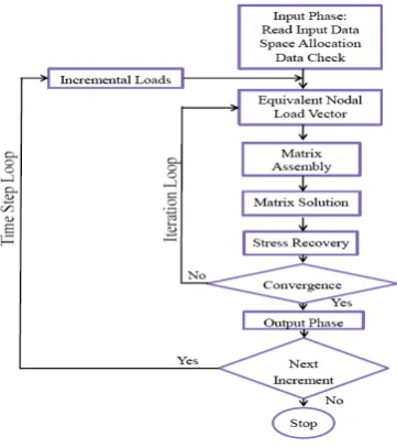
[image:4.595.206.387.305.509.2]Computational work was conducted using MSC Nastran 2014 software to study the characterization of secondary creep behaviour in tensile creep test simulation. This software offers SOL 400 modules which have the nonlinear capabilities to analyse a wide variety of structural problems subjected to geometric and material nonlinearity. In order to model the creep characteristics, a few options need to be considered in the analysis such as the CREEP option to identify the creep time behaviour of the material, the MATVP option to describe the materials properties and the NLSTEP bulk data entry for controlling the time integration in the finite element program. The flow diagram of non-linear problem analysis for the simulation work is shown in Figure 1. This analysis is a quasi-static analysis, using adaptive time stepping for real-time creep, with geometric and material nonlinearity due to large strain and creep. Uniaxial tensile creep test is illustrated computationally in 2D-analysis and discretization is shown in Figure 2. This model consists of 36, 4-node plane strain elements and 49 nodes.
Figure 1. Flow diagram of non-linear creep analysis
[image:4.595.198.402.549.732.2]
4
MATHEMATICAL MODELLING
Conventional creep behaviour is based on a Von Mises creep potential with isotropic behaviour described by the equivalent creep law:
(1)
The material behaviour is therefore described by:
(2)
where is the outward normal to the current Von Mises stress surface and is the
equivalent creep strain rate. There are two numerical procedures used in implementing creep behaviour. The default is an explicit procedure in which the above relationship is implemented in the program by an initial strain technique. In addition, a pseudo-load vector due to the creep strain increment is added in the stiffness equation as:
(3)
where K is the stiffness matrix, is the incremental displacement, is the
incremental nodal force vectors and is the pseudo-load vector due to the
creep strain increment in which is the strain displacement relation and D is the stress-strain relation [9].
The dependence of equivalent creep strain rate on any independent parameter can be given directly in power law form. The equivalent creep strain rate is:
(4)
where A, p and q are the material constants, n is a stress exponent, and , , T and t are equivalent stress, equivalent creep strain, temperature and time, respectively. For this analysis, only the stress and temperature parameters will be identified. Equation 5 is simplified as:
(5)
The expression, , sometimes called Norton’s law, provides the basic power law
5
RESULTS AND DISCUSSION
Mesh Convergence
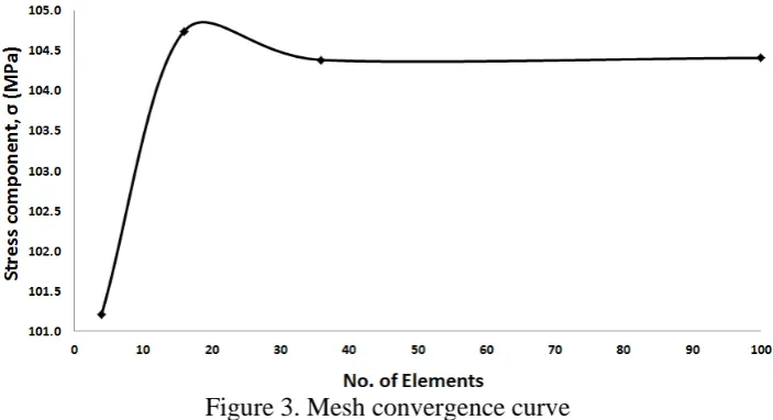
[image:6.595.121.473.251.442.2]In order to identify the adequate size of meshing, a mesh convergence curve was created through the analysis. Figure 6 shows the mesh convergence curve that exhibits the best relationship between the stress and the number of elements of specimen structure in the finite element analysis. The stress increases with an increasing number of elements, until at 30 elements; it starts to converge and reaches a stable form. Therefore, 36 elements were chosen in this analysis to achieve mesh convergence stability and to get a symmetrical geometry number of elements.
Figure 3. Mesh convergence curve
Power Law of Creep
Firstly, the relationship of creep strain rate and stress was analysed and as shown in Figure 4. From the graph, the exponential curve is formed which actually expressing a
Norton’s Law relation. The creep strain rate of the copper alloy increased with increasing of the stress respectively [10]. Theoretically, the function of the Power-law creep depends on the variable of material constant, A, and the stress exponent, n, of the material [11]. An experimental result was also plotted in the same graph to clarify the
6
Figure 4. Power Law relation between creep strain rate and stress for experimental and simulation results
Stress Dependence Analysis
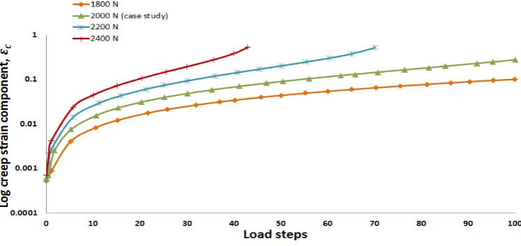
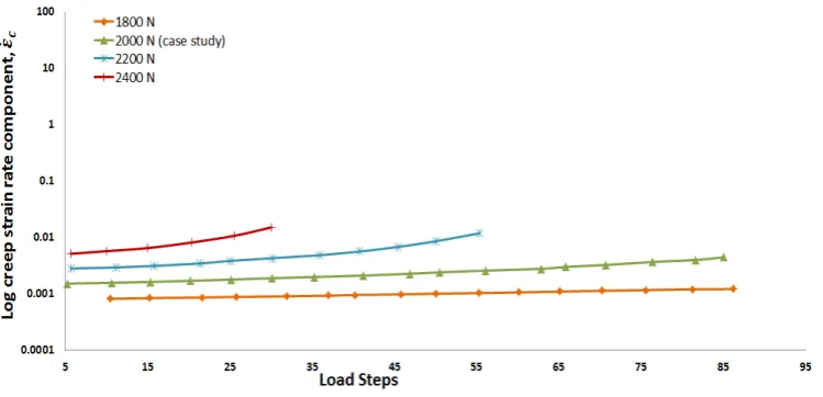
Secondly, in order to determine the secondary creep behaviour of copper alloy, the creep rate curve relationship between creep strain and creep strain rate with respect to time (load steps) were plotted (as shown in Figures 5 and 6). Figure 5 shows the schematic creep curves at the same temperature that represents secondary creep strain with load steps. In order to see the influence of the stress in the creep strain formation, the values of stress were manipulated through the analysis and the results obtained are plotted together. By increasing the stress respectively, the secondary creep strain were also increases and the rupture lifetime of material decreases on increment of the stress. The pattern of the plotted creep curves shows similar results to those studied by [1,5,12-15], which imitate the secondary creep regime. Moreover, the creep strain rate forms an approximately a steady state as shown in Figure 6. The stresses applied typically affect the formation of creep strain rate and also rupture lifetime of the material.
[image:7.595.111.484.551.727.2]7
Figure 6. Creep strain rate as a function of time/load steps at a temperature of 473 K
CONCLUSION
This study is to characterize the secondary creep behaviour of copper alloy using the Power-law as a constitutive creep model. To develop this case study, a computational approach was presented in the uniaxial creep test with constant stresses and temperature condition. As a result, the graph of creep strain rate against stress was identified as being representative of secondary creep behaviour, and with 5.1% of error, there was good agreement between the simulation model and the experimental results. Moreover, the graphs for creep strain and creep strain rate with load steps were presented which represent the secondary creep regime. The variations of the stresses give the primary factor that affects the formation of creep strain and also rupture life of the material. The highest value of stresses creating a significant impact toward creep strain and shorten the failure lifetime of the material. Therefore, the simulation model, based on a Norton’s Law equation, provides the basics for the Power law relationships that have been widely used to describe secondary creep behaviour. In order to develop the knowledge of creep failure, the estimation creep model will be drawn up to predict the creep damage behaviour by considering the creep crack initiations and creep crack growth model of materials.
ACKNOWLEDGEMENTS
8
REFERENCES
[1] M. Cowan and K. Khandelwal. Modeling of high temperature creep in ASTM
A992 structural steels. Engineering Structures 2014; 80: 426-434.
[2] J.-T. Li, X.-M. Rong, J.-L. Wang, B.-Q. Zhang, and X.-J. Ning. A universal function of creep rate. Chinese Physics B 2015; 24: 093401.
[3] Yao, H.-T., Xuan, F.-Z., Wang, Z., & Tu, S.-T. A review of creep analysis and design under multi-axial stress states. Nuclear Engineering and Design 2007; 237(18): 1969-1986.
[4] L.-J. Xie, X. Ren, M.-X. Shen, and L.-Q. Tu. Parameter correlation of high-temperature creep constitutive equation for RPV metallic materials. Journal of Nuclear Materials 2015; 465: 196-203.
[5] J. T. Maximov, G. V. Duncheva, A. P. Anchev, and M. D. Ichkova. Modeling
of strain hardening and creep behaviour of 2024T3 aluminium alloy at room and high temperatures. Computational Materials Science 2014; 83: 381-393. [6] Cui, Y., Sauzay, M., Caes, C., Bonnaillie, P., & Arnal, B. Modeling and
Experimental Study of Long Term Creep Damage in Austenitic Stainless Steels. Procedia Materials Science 2014; 3(0): 122-128.
[7] Mackerle, J. Creep and creep fracture/damage finite element modelling of engineering materials and structures: an addendum. International Journal of Pressure Vessels and Piping 2004; 81(5): 381-392.
[8] Evans, R., Wilshire, B. Introduction to creep. The Institute of Materials; 1993.
[9] MSC Nastran 2014.1. Nonlinear User’s Guide SOL 400; 2015: 558 - 563.
[10] Larsson, J. Evaluation of current methods for creep analysis and impression creep testing of power plant steels. Master of Science Thesis, Material Science and Engineering. KTH Royal Institute of Technology 2012.
[11] H. Takagi, M. Dao, and M. Fujiwara. Prediction of the constitutive equation for
uniaxial creep of a Power-law material through instrumented microindentation testing and modeling. The Japan Institute of Metals and Materials 2014; 55(2): 275-284.
[12] Zhisheng, Z., Pingliang, C., Zhiqiang, L., Ningbo, L., Shun-Peng, Z., & Hong-Zhong, H. Notice of retraction creep life prediction model of aircraft turbine disc alloy based on continuum damage mechanics. International Conference on the Quality, Reliability, Risk, Maintenance, and Safety Engineering (QR2MSE) 2013; 1018-1021.
[13] L.-T. Li, Y. C. Lin, H.-M. Zhou, and Y.-Q. Jiang. Modeling the
high-temperature creep behaviors of 7075 and 2124 aluminum alloys by continuum damage mechanics model. Computational Materials Science 2013; 73: 72-78. [14] Y. C. Lin, Y.-C. Xia, M.-S. Chen, Y.-Q. Jiang, and L.-T. Li. Modeling the
creep behavior of 2024-T3 Al alloy. Computational Materials Science 2013; 67: 243-248.