A COUPLED SIMULATION METHOD FOR A VORTEX-INDUCED VIBRATION SYSTEM
MONG GUO REN
This report is submitted
in fulfillment of the requirement for the degree of Bachelor of Mechanical Engineering (Thermal-Fluids)
Faculty of Mechanical Engineering
UNIVERSITI TEKNIKAL MALAYSIA MELAKA
DECLARATION
I declare that this project report entitled “A Coupled Simulation Method For A Vortex-Induced Vibration System” is the result of my own work except as cited in the references
APPROVAL
I hereby declare that I have read this project report and in my opinion this report is sufficient in terms of scope and quality for the award of the degree of Bachelor of Mechanical Engineering (Thermal-Fluids).
DEDICATION
i ABSTRACT
ii
ABSTRAK
iii
ACKNOWLEDGEMENT
Firstly I would like to thank God for giving me this opportunity to study in UTeM and having this chance to complete my Final Year Project.
Dr. Cheng See Yuan who is my supervisor deserve my gratitude and appreciation. Thank him for giving me this opportunity to carry out my final year project research with him. His guidance throughout the whole year and encouragement when I needed it most has supported me both physically and mentally.
Secondly, I would like to thank my family members that gave me mental support until the completion of this project. My friends, coursemates who have been with me through thick and thins makes me who am I today. They too deserve my gratitude.
iv
TABLE OF CONTENTS
PAGE DECLARATION
DEDICATION
ABSTRACT i
ABSTRAK ii
ACKNOWLEDGEMENT iii
TABLE OF CONTENTS iv
LIST OF FIGURES vi
LIST OF TABLE viii
CHAPTER
1. INTRODUCTION 1
1.1 Background 1
1.2 Problem Statement 2
1.3 Objectives 3
1.4 Scopes Of Project 3
2. LITERATURE REVIEW 4
2.1 Fluid Structure Interaction (FSI) 4
2.1.1 Vortices Induced Vibration (VIV) 5
2.1.1.1 Factors Affecting VIV 6
2.1.1.2 Wake Region in VIV 7
2.2 Airfoil 8
2.3 Mass Spring Damper System 10
2.3.1 Natural Frequency 11
3. METHODOLOGY 12
3.1 Computer Aided Engineering (CAE) 15
3.2 Identification of Cross-Section 15
3.3 Geometry Drawing 15
3.4 Mesh Generation 16
3.5 Solver 18
3.6 Pre-Processing 19
3.7 Flow Chart 20
4. RESULT AND DISCUSSION 21
v
4.2 Grid Independence Test 23
4.3 Stiffness vs Body Motion 24
4.4 Stiffness vs Strouhal Number 30
4.5 Discussion on Non-Existence of Fluid Structure Interaction 36
5. CONCLUSION AND RECOMMENDATION 38
REFERENCES 40
APPENDIX A Gantt Chart PSM I 45
vi
LIST OF FIGURES
FIGURE TITLE PAGE
2.1 Detailed Sketch Of Flow Near Separation (Hansen et al., 2015) ... 6
2.2 Relationship of Airfoil Performance and Its Dimension (Ahzalilov, 1996) ... 8
2.3 Vortex Generation From End Plates (Meederira, 2014) ... 9
2.4 Mass-Spring-Damper System ... 10
3.1 Mesh Setup for circle ... 13
3.2 User Defined Function using 6DOF ... 14
3.3 Mesh Generation for NACA0018 Airfoil ... 17
4.1 Flow Separation At Rear End Of NACA0018 Airfoil ... 21
4.2 Vortex Street Formation ... 22
4.3 Fluctuating Lift Force for a Fixed Airfoil System ... 23
4.4 Frequency of Lift Graph for Fixed Airfoil System ... 23
4.5 Lift Data Trend for Grid Independent Test (Lift Magnitude & Strouhal Number) ... 24
4.6 UDF Setting for NACA0018 Airfoil – 1DOF Motion ... 25
4.7 Motion of Airfoil in Y-Axis with RE100,000 and Stiffness 50K ... 26
4.8 CG Motion of Airfoil System with Natural Frequency 1.59Hz ... 26
4.9 Frequency of CG Motion Natural Frequency 1.59Hz ... 27
4.10 CG Motion of Airfoil System of Natural Frequency 5.03Hz ... 27
vii
4.12 Graph of System Stiffness against Body Movement along Y-Axis ... 30
4.13 Lift Data NACA0018 with Natural Frequency 1.59Hz ... 30
4.14 Frequency of Lift Data NACA0018 with Natural Frequency 1.59Hz .. 31
4.15 Lift Data NACA0018 with Natural Frequency 5.03Hz ... 31
4.16 Frequency of Lift Data NACA0018 with Natural Frequency 5.03Hz .. 32
4.17 Lift Force Comparison for Different System Stiffness in Simulation Time ... 32
4.18 Monitor Point Setup To Collect Pressure Changes Due To Vortex Shedding ... 33
4.19 Pressure Fluctuation at Vortex Street ... 33
4.20 Frequency of Pressure Change ... 34
viii
LIST OF TABLE
TABLE TITLE PAGE
3.1 Validation Result 14
4.1 Grid Independent Test on Fix Airfoil Profile 24
4.2 System with Different Stiffness 25
4.3 Data Comparison for System Stiffness and Body Motion 29
4.4 Comparison System Stiffness with Strouhal Number 34
4.5 Comparison Between Vortex Shed Frequency & Airfoil Motion
Frequency for Re100,000 35
1 CHAPTER 1
INTRODUCTION
1.1 Background
An object subjected to flowing fluid will experience a phenomenon known as fluid structure interaction. This interaction will generate resultant force that is resolved into the lift and drag directions for convenient in the analysis.. When fluid encounter a blunt object,
wake region will present behind the body where back flow takes place. One types of wake is in vortices form. This phenomenon is due to separation of boundary layer that bounds the wake and free stream which leads to fluid rotation. These rotating fluid result in formation of individual vortex which sheds at the rear end of the body and travel down the wake. Typically, an vortex shedding which is periodic and in alternating form will take place in the wake field, this is called a vortex street.
At some instances, the vortex shedding has a pattern which is not symmetrical about the body. There are some vortices being shed on the top surface of the body and some are at the bottom of the surface. This will cause irregular pressure distribution on the body hence causing lift force at both sides of the body to be exerted periodically. This occurrence is known as vortices induced vibration (VIV). This periodic shedding action has its own frequency. When the body‟s natural frequency matches with the frequency of this oscillation, „Lock-in‟ or also known as resonance will happen. This will amplifies the body amplitude of vibration creating displacement on the object.
2
A fixed body experiencing fluid induced vibration will has a different wake region when compared to an elastically mounted body which is allows to moves. These elastically mounted bodies will experience a motion which is in translation or rotation or both. This means that the body will moves whenever there is fluid induced effect on the body. At this moment the wake region of the body might be affected as the moving body will cause a change in the body orientation. When the wake region changes it will affect lift and drag forces of the body in the flow field. Hence it is important to know whether the body motion affect flow behaviour when compared to a fixed body where the wake is constant throughout.
1.2 Problem Statement
There are numerous objects of various shapes that experience fluid flow for example house, bridge, fan, trees etc. Fluid structure interaction is the phenomena that occurs when a flowing fluid encounter an object. During this interaction, the objects will response in a particular way due to the flowing fluid. This is known as the fluid induced effect. In many simulations, the response of body which sometimes comes in translational and rotational manner or even deformed object is neglected. This reduces the simulation time and simplified the simulation case. However in real life situation, this response of the body is present and might cause changes to the properties or performance of the system.
Different sectional object will react differently. In this project an airfoil cross-section shape is chosen to be investigated. This is because there are lots of airfoil applications around us for example the spoiler of a car, the wing of an airplane, blade of a helicopter, blade of fan, blade of wind turbine and blade of compressor rotor.
3
frequency, magnitude of lift force and magnitude of airfoil movement along the y-axis will be determine by manipulating the stiffness of the system and the fluid‟s Reynolds Number.
1.3 Objectives
The objectives of this project are as follows:
To identify flow behaviour in fix body simulation and moving (1DOF) rigid body simulation
To examine impact of body motion on flow characteristics To identify the vortex shedding in wake region of airfoil.
To observe the effect of aerodynamic forces on an elastically mounted airfoil
1.4 Scopes Of Project The scopes of this project are:
Fixed airfoil simulation to identify vortex shedding
Simulation of elastically mounted (1DOF) airfoil (rigid body) with different stiffness
4 CHAPTER 2
LITERATURE REVIEW
2.1 Fluid Structure Interaction (FSI)
Fluid Structure Interaction is the phenomenon that occurs at the interphase between an object and the surrounding environment fluid. Whenever fluid flow passes a stationary object or a moving object moving pass a stationary fluid domain, there will be effect imposed by both the fluid and object on each other. Happenings of FSI which can be seen at for instance oil-rig risers and bridge (Zahari & Dol, 2014) and in medical tools (Hessenthaler et al., 2016) involve the coupling of unsteady fluid flow and structure motion. The mechanism that causes elastic structure to vibrates and turn to self-excite while submerge in a flowing fluid is hard to estimate and predict due to mechanical properties of structures and properties of the fluid itself.
5
which experience FSI are among the topic of interest of structural engineers as they provides useful and relatable information to the objects in our daily lives.
2.1.1 Vortices Induced Vibration (VIV)
Vortices Induced Vibration (VIV) is a typed of FSI that happens on a structure. This is an effect of vortices shedding in the wake flowing through bluff body structure such as column, risers and mooring lines. Structure Hydrodynamic loading will be affected by change in vortices which will cause structure to vibrate (Nguyen & Nguyen, 2016). VIV occurs when pressure on surface fluctuates; this leads to fluctuates of lift force thus producing cross stream oscillation. These oscillations sometimes can be large and sometimes is too small to notice depends on the wake behind the object. Gharib, (1999) experiments using cylinder of various mass ratio states that the vortex wake tends to be almost identical regardless of the geometry being simulated. This also means that object subjected to fluid flow will experience either little or a large amount of vortex wake where fluid separation occur at the rear end of the body. There is presence of vortex shedding behind the race car clean wing and a shear layer between regions of positive and negative vorticity (Kuya, et al, 2009). This confirms that although the wind is aerodynamic in size, there is also vortex formation which is due to wake region.
Hansen, (2007) carried out an experiment in wind tunnel using geometry with different cross-section. Among the tested geometries are circular cylinder, sharp-edged sections, octagons and bridge decks. From the result of Hansen, (2007), significant vibration level will causes displacement of structure when the wind reaches slightly above 6m/s. This shows activity of VIV on these structures with different cross-section caused by the flowing wind.
6
that WIV happened only when there is wake region that contains sufficiently large pressure differences or also can be known as Karman Vortex Street.
2.1.1.1 Factors Affecting VIV
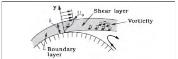
[image:18.595.153.458.463.564.2]In Pantazopoulos & Pantazopoulos findings, (1994), they state that important parameters in VIV are lift coefficient, shedding frequency (Strouhal number), correlation length and shedding frequency bandwidth. Hansen et al., (2015) mention VIV measured in dynamic test rig depends strongly on Reynolds Number. Bluff bodies surface will always experience region of vorticity where flow is more or less coherent. Figure 2.1 (Hansen et al., 2015) provides clear visualization on the flow separation region on bluff body where back flow occur which leads to formation of small votrices in the shear layer region near the boundary of the object. On sharp-edge body separation flow defined by location of edges while rounded bodies depends on air velocity which is also directly related to Reynolds number.
Figure 2.1: Detailed Sketch Of Flow Near Separation (Hansen et al., 2015)
Hansen et al., (2015) uses different configuration of streamlined single box grinder to investigate the effect of VIV. It is found that Strouhal number increase with Reynolds number and the resonance wind velocity for VIV is governed by Strouhal number.
7
motion tranverse to the flow. Strouhal Number which is an important term in vortex shedding is shown in equation below.
(2.1)
Where is the vortex shedding frequency at rest, is the diameter of circular cylinder and V is the velocity of ambient flow. Frequency of vortex shedding is related to Reynolds number, Re which is also linked to flow velocity, viscosity of fluid and characteristic length of object (Abhiroop Jayanthi, 2008).
A new parameter termed „effective stiffness‟ by Gharib, (1999) will also affect the chances of VIV. By reducing the structure to fluid mass ratio, lock-in behaviour or resonance can also be prevented. However it is also found out that at low mass ratio, VIV can occur with or without lock-in behaviour. Self-excite oscillation and forced oscillations are the types of VIV where self-excited oscillation occurs naturally and forced oscillation can be controlled independently of fluid velocity.
2.1.1.2 Wake Region in VIV
Williamson & Govardhan, (2004) uses an elastically mounted cylinder as an example for VIV system. Certain wake pattern is induced by body motion for example the 2P, 2S, P, C and S mode. These are all due to imbalance pressure distribution across the surface of the body of cylinder when fluid flows pass it.
An object experiencing fluid flow will experience two effects which is drag force and lift force. When an object subjects to VIV, fluctuating lift force can be seen on a body. When the pressure of both upper and lower side of the object fluctuates with time, the lift will be affected too. These are dimensionless coefficients defined by:
8
(2.3)
Where and are the lift and drag forces, p is the density of the fluid and V is the velocity. and are reference area. The size of the wake region will determine the magnitude of these two forces acting on the body(Lienhard, 1966).
2.2 Airfoil
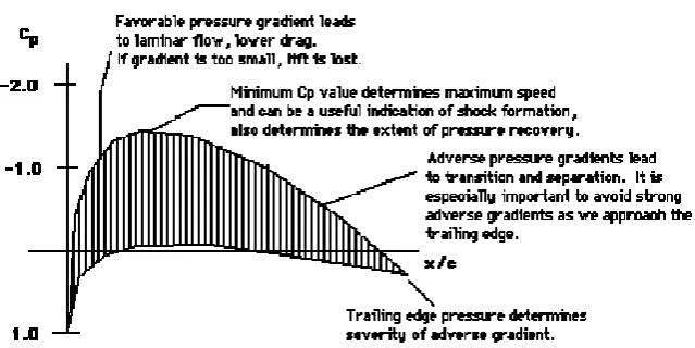
[image:20.595.139.459.577.737.2]Airfoil shape is used in car spoiler and wing, this shape is usually inverted to provide desired effects. Inverted airfoil has a low pressure suction region on the lower surface and high pressure suction region on the higher surface of airfoil geometry. Airfoil geometry can be summarize by few parameters for example are maximum thickness, maximum chamber, position of max thickness and many more. Ahzalilov, (1996) found out that shape of pressure distribution relates closely to airfoil performance as shown in Figure 2.2. It is shown that the geometry or design of the cross-section will cause the pressure distribution across the airfoil surface to change. Holmes, (2008) state that large wing surface area creates more lift while the increase of aspect ratio will induce less air resistance. Breu,et al, (2008) also mention that the drag reduction of a vehicle by implementing a rear spoiler is strongly dependent on the shape of spoiler.
9
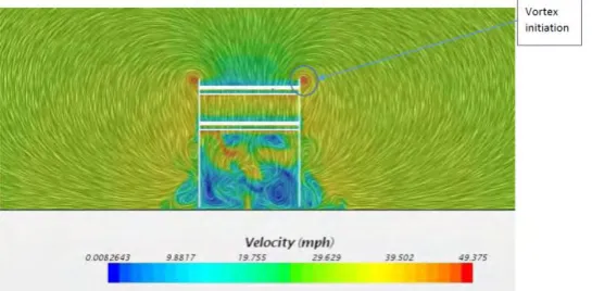
[image:21.595.171.444.459.593.2]Since most aerofoil profile is used in airplane to create a large lift while taking off, by inverting the shape it will create a sufficient negative lift force also known as down force on the vehicle. Stiffness of system will affect the behaviour of the aerofoil which the dynamic response of the aerofoil is dependent on the location of pitching axis says (Z.Peng, 2009). Experiment on spoiler effect on wake region was carried out by et al, (2011) and its found out that the deflection of spoiler enlarge the wake region by 0.79%. Tsai, et al, (2009) also found out that by installing spoiler, lift coefficient can be reduced which leads to improved high speed driving condition and vertical stability of driving. From the experiment, when spoiler is placed on the trunk top, drag coefficient increase while lift coefficient decreases. Trailing vortex that is similar to that of a flying plane is produce due to pressure difference on the upper and lower surface of spoiler. This phenomenon also occurs in the work of Meederira, (2014) which saw vortex generation from end plates which can be seen in Figure 2.3. This shows that fluid flowing pass a airfoil profile will generate vortex in the wake region.
Figure 2.3Vortex Generation From End Plates (Meederira, 2014)
10
however at some angle flow separation happens and enlarge which will reduce the lift coefficient. Huang (2011) states airfoil when placed at post-stall angle of attack might response as if a bluff body. Flow separation problem can be tackle through element of high aspect ratio. Other than that, endplates of the rear wing in 3D simulation avoid trailing vortices formation which is due to air leakage in wing tip. Experiments carried out by Elsayed et al., (2011) found out the fixing spoiler on aircraft wings is able to accelerate vortex breakdown in the wake region. By deflection spoiler by 10° peak vorticity value is reduced to 0.46.
2.3 Mass Spring Damper System
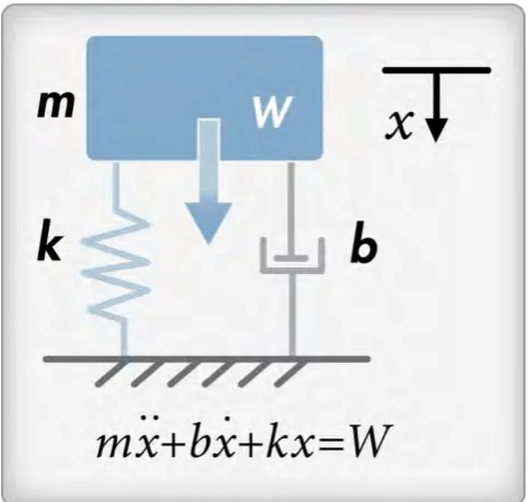
[image:22.595.184.427.443.672.2]Mass spring damper system is used in many experiments especially those that involve object‟s motion. Equation that govern the object in this system is ̈ ̇ shown in Figure 2.4. Zhang & Ji, (2016) uses an elastically mounted 2DOF system that include an airfoil and circular shape.
Figure 2.4 Mass-Spring-Damper System
11 2.3.1 Natural Frequency
The natural frequency of a system is the frequency where system oscillates when it is acted by an external force. The natural frequency of a system is calculated by,
√ (2.4)
Resonance or lock-in occurs when the natural frequency of the structure is in sync with the frequency of an outside force. During this period, exceptionally strong response will be obtained from the structure causing the structure to vibrate or moves with great amplitude. In Derakhshandeh, et al, (2016) free-decay tests are conducted to obtain the natural frequency of the fundamental bending mode of the cantilevered aerofoil. From the dynamic response of the subject, 4.70Hz is the natural frequency of the cantilevered beam which is away from the frequency of oscillation hence structure does not experience resonance effect.
12 CHAPTER 3
METHODOLOGY
Circle shape is the most common cross-section used in Vortex Induced Vibration study such as by Singh & Mittal, (2005) and Mysa, et al, (2016). The shape or cross-section of the object to be studied needed to be determined. Review from previous study found out that there are lots of researches on airfoil profile in laminar flow but there are not many studies on turbulent flow. Hence this work will focus on turbulent flow across airfoil cross-section shape. The shape of airfoil comes in many while most profiles are based on NACA number. A symmetry profile of NACA0018 which has been investigate its properties by Nakano, et al, (2007) is chosen to be investigated.
First and foremost the formation of vortex is to be observed behind the airfoil. This is done to show vortex shedding behind airfoil profile as found by Meederira, (2014). If vortex shedding is not observed, the angle of attack, AOA of the airfoil is adjusted and re-run the simulation. After obtaining steady vortex shedding, fast fourier transform, FFT is done on the oscillating lift data to find its peak frequency which is the vortex shedding frequency.