UNIVERSITI TEKNIKAL MALAYSIA MELAKA
ACCURACY STUDY OF IMPELLER ON FIVE-AXIS AND NINE-AXIS MACHINE BY USING POWERMILL AND CATIA
This report submitted in accordance with requirement of the Universiti Teknikal Malaysia Melaka (UTeM) for the Bachelor’s Degree in Manufacturing Engineering
Technology (Process and Technology) with Honours.
by
LEE HOOI FONG B071410257 940630-10-6468
UNIVERSITI TEKNIKAL MALAYSIA MELAKA
BORANG PENGESAHAN STATUS LAPORAN PROJEK SARJANA MUDA
TAJUK: Accuracy Study of Impeller on Five Axis and Nine Axis Machine by using PowerMILL and CATIA
SESI PENGAJIAN: 2017/18 Semester 1
Saya LEE HOOI FONG
mengaku membenarkan Laporan PSM ini disimpan di Perpustakaan Universiti Teknikal Malaysia Melaka (UTeM) dengan syarat-syarat kegunaan seperti berikut:
1. Laporan PSM adalah hak milik Universiti Teknikal Malaysia Melaka dan penulis. 2. Perpustakaan Universiti Teknikal Malaysia Melaka dibenarkan membuat salinan
untuk tujuan pengajian sahaja dengan izin penulis.
3. Perpustakaan dibenarkan membuat salinan laporan PSM ini sebagai bahan pertukaran antara institusi pengajian tinggi.
4. **Sila tandakan ( )
SULIT
TERHAD
TIDAK TERHAD
(Mengandungi maklumat yang berdarjah keselamatan atau kepentingan Malaysia sebagaimana yang termaktub dalam AKTA RAHSIA RASMI 1972)
(Mengandungi maklumat TERHAD yang telah ditentukan oleh organisasi/badan di mana penyelidikan dijalankan)
Alamat Tetap:
NO. 8 Jalan Khoo Kek Keng 3
Taman Kapar 42200
Klang, Selangor Darul Ehsan
Disahkan oleh:
FAKULTI TEKNOLOGI KEJURUTERAAN
Tel : +606 234 6623 | Faks : +606 23406526
Rujukan Kami (Our Ref) : Rujukan Tuan (Your Ref) :
12 DEC 2017
Pustakawan
Perpustakaan UTeM
Universiti Teknikal Malaysia Melaka Hang Tuah Jaya,
76100 Durian Tunggal, Melaka.
Tuan/Puan,
PENGKELASAN LAPORAN PSM SEBAGAI SULIT/TERHAD LAPORAN PROJEK SARJANA MUDA TEKNOLOGI KEJURUTERAAN PEMBUATAN (PROSES DAN TEKNOLOGI): LEE HOOI FONG
Sukacita dimaklumkan bahawa Laporan PSM yang tersebut di atas bertajuk
“Accuracy Study of Impeller on Five Axis and Nine Axis Machine by using PowerMILL and CATIA” mohon dikelaskan sebagai *SULIT / TERHAD untuk tempoh LIMA (5) tahun dari tarikh surat ini.
2. Hal ini adalah kerana IANYA MERUPAKAN PROJEK YANG DITAJA
OLEH SYARIKAT LUAR DAN HASIL KAJIANNYA ADALAH SULIT.
Sekian dimaklumkan. Terima kasih.
Yang benar,
________________
Tandatangan dan Cop Penyelia
* Potong yang tidak berkenaan
DECLARATION
I hereby, declared that this report entitled “ACCURACY STUDY OF IMPELLER ON FIVE-AXIS AND NINE-AXIS BY USING POWERMILL AND CATIA” is the
result of my own research except as cited in reference.
Signature :
Author’s Name : LEE HOOI FONG
APPROVAL
This report is submitted to the Faculty of Engineering Technology of UTeM as a partial fulfilment of the requirements for the degree of Bachelor of Manufacturing Engineering Technology (Process and Technology) with Honours. The member of the supervisory is as follow:
ABSTRAK
Pada zaman yang moden ini, pelbagai jenis mesin CNC dapat diperoleh dalam pasaran dan mesin CNC terbaru adalah mesin CNC dengan sembilan paksi. Tujuan membuat kajian ini adalah untuk mengkaji ketepatan mesin CNC lima paksi dan mesin CNC sembilan paksi dengan menghasilkan produk yang sama dalam parameter yang sama tetapi dengan cara pemesinan dan perisian CAM yang berbeza. Cara untuk membuat kajian ini adalah menggunakan perisian CAM yang berbeza sebagai pengantaraan. PowerMILL adalah digunakan untuk mesin CNC lima paksi manakala CATIA adalah digunakan untuk mesin CNC sembilan paksi. Pendesak yang mempunyai permukaan geometri yang kompleks telah dihasilkan oleh kedua-dua mesin. Mesin 3D scanner digunakan untuk menganalisis dimensi pendesak yang dihasilkan. Keputusan yang diperolehi telah ditafsirkan dan perbandingan prestasi ketepatan antara kedua-dua keputusan telah dibuat. Berasaskan keputusan perbandingan yang didapatkan, ketepatan PowerMILL program adalah 75.80% dalam toleransi manakala ketepatan CATIA program adalah 36.80% dalam toleransi.
ABSTRACT
Today there are many type of CNC machines in the market and the latest CNC machine is nine-axis turn/mill machine. The purpose of this paper is to study the accuracy on five-axis and nine-axis CNC machine by produce a same part with same parameter but different cutting strategies and CAM software. The method use to study accuracy of machine is by using different CAM software as the post processor. PowerMILL is used for the five-axis machine while CATIA is used for the nine-axis machine. Impeller, which has a complex geometry surfaces is produce by both machines. 3D scanner machine is use to analyse the accuracy of impeller produced. The result obtained is interpret and comparison accuracy of both results are made. Based on the comparison, the accuracy of the CAM program of PowerMILL, which is 75.80% in the range of tolerance, is more accurate than the CAM program of CATIA, which is 36.80% in the range of tolerance.
DEDICATION
ACKNOWLEDGEMENT
Firstly, I would like to thanks to my university, University Teknikal Malaysia Melaka (UTeM) giving me the opportunity to do this project. I had gained much of knowledge when doing this project.
Next, I would like to thanks to my supervisor, Mr Muhammad Syafik Bin Jumali, who help me much when doing this project. When I had confuse in my project, my supervisor had guide me and motivated me to do the project in the right way.
I also like to take this opportunity to thank to all lab assistance in UTeM. With the help of the lab assistance, I had complete my project smoothly.
TABLE OF CONTENT
Abstrak i
Abstract ii
Dedication iii
Acknowledgement iv
Table of Content v
List of Table viii
List of Figures ix
List of Abbreviations, Symbols, and Nomenclatures xii
CHAPTER 1: INTRODUCTION 1
1.1 Background 1
1.2 Problem Statement 4
1.3 Objective 4
1.4 Scope 5
CHAPTER 2: LITERATURE REVIEW 6
2.1 Accuracy 6
2.1.1 Method of accuracy study 10
2.2 Impeller 11
2.3 Five-axis Machine 14
2.4 Nine-axis Machine 16
2.5 3D Scanner 19
2.6 CAM Software 21
2.7 Materials 23
CHAPTER 3: METHODOLOGY 25
3.1 Project Planning 25
3.2 Phase 1 29
3.2.1 Problem Formulation 29
3.2.2 Objective Setting 30
3.2.3 Literature Study 30
3.2.4 Create a Suitable CAD Model 31 3.2.5 Material and Cutting Tools used 32
3.3 Phase 2 33
3.3.1 PowerMILL CAM Program 33
3.3.1.1 Model Area Clearance 37
3.3.1.2 Radial Finishing 39
3.3.1.3 Blisk Area Clearance 42
3.3.1.4 Hub Finishing 44
3.3.1.5 Blade Finishing 47
3.3.2 CATIA CAM Program 49
3.3.2.1 Roughing 53
3.3.2.2 Profile Contouring 55
3.3.2.3 Isoparametric 58
3.3.2.4 Multi-axis Contour Driven 61
3.3.3 Post Processing 66
3.3.4 Physical Machining 67
3.3.5 Dimensional Analysis 69
CHAPTER 4: RESULT AND DISCUSSION 71
4.1 Results 71
4.2 Problem of CAD Model 74
4.3 Problem of Machined Part 75
4.4 Problem of Analyse Accuracy of Impeller 77
CHAPTER 5: CONCLUSION AND RECOMMENDATION 79
5.1 Conclusion 79
5.2 Recommendation 80
REFERENCE 81
APPENDICES
LIST OF TABLE
3.1 Detail dimension of Impeller 31
3.2 Setting of Model Area Clearance 37
3.3 Setting of Radial Finishing 39
3.4 Setting of Blisk Area Clearance 42
3.5 Setting of Hub Finishing 44
3.6 Setting of Blade Finishing 47
3.7 Detail of Setting in Roughing Process 54
3.8 Setting of Profile Contouring 56
3.9 Setting of Isoparametric 58
LIST OF FIGURES
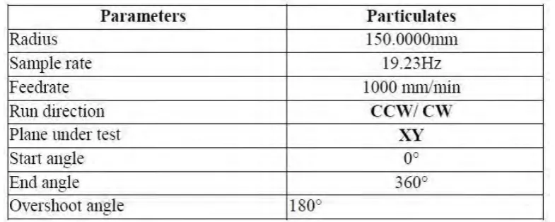
2.1 Test Parameter of Ballbar Test 7
2.2 Quality Improvement after Condition Monitoring 8 2.3 Productivity Improvement after Condition Monitoring 8
2.4 Renishaw Ballbar QC-20 9
2.5 Principle of measurement with Renishaw equipment QC-20 Ballbar
10
2.6 Shape of Impeller 12
2.7a Setup Layers of Cutting Surface 12
2.7b Rough Cutting in Reciprocating Mode 12
2.7c Rough Finishing in Contouring Mode 12
2.8 Tool Path for Slotting 13
2.9 Tool Path for Expansion Slotting 14
2.10 Axis indicate in five-axis machine 15
2.11 Feed rate change curve of four-axis and five-axis 16 2.12 Applicable workpiece types by turn-milling 17 2.13a Kinematics scheme of coaxial turn milling 18 2.13b Pratical example for an elliptic section hub 18 2.14a Orthogonal turn milling with entire tool 18 2.14b Orthogonal turn milling with insert tool 18 2.15 Result Evaluated by Using VolumeGraphics VGStudio MAX 2.2 19
2.16 Flow Chart of Scanning Process 20
2.17 Flowchart of a CAM software to program a part 22
2.18 Machining strategies 22
2.19 Mechanical properties of impeller materials 23 2.20 Variation of maximum Von-Mises Stress of blade for different
materials
24
2.21 Variation of maximum deformation of blade for different materials 24
3.3 Block and Axis created 33
3.4 Workplanes, Levels and Sets Created 33
3.5 Tab of Safe Area 34
3.6 Tab of Start and End Point 35
3.7 Flow Chart of Machining Process in PowerMILL 36 3.8 Simulation Before and After of Model Area Clearance 39 3.9 Simulation Before and After of Radial Finishing 41 3.10 Simulation Before and After of Blisk Area Clearance 44 3.11 Simulation Before and After Hub Finishing 46 3.12 Simulation Before and After Blade Finishing 49 3.13 Stock, Planes and Axis System Created 49 3.14 Assembly of Plane System and Impeller 50
3.15 Step to go into Machining Workbench 50
3.16 Setting in Part Operation Page 51
3.17 Flow Chart of the Machining Process in CATIA 52 3.18 Simulation Before and After of Roughing Process 55
3.19 Area Apply Profile Contouring 55
3.20 Simulation Before and After of Profile Contouring 1 57 3.21 Simulation Before and After of Profile Contouring 2 57 3.22 Simulation Before and After of Isoparametric 1 60 3.23 Simulation Before and After of Isoparametric 2 61 3.24 Simulation Before and After of Isoparametric 3 61 3.25 Simulation Before and After Multi-axis Contour Driven 1 65 3.26 Simulation Before and After Multi-axis Contour Driven 17 65 3.27 Simulation Before and After Multi-axis Contour Driven 12 65
3.28 Post-processor of 9-axis Machine 66
3.29 NC Code Generate by CATIA 66
3.30 NC Code Generate by PowerMILL 67
3.31 One of the Summary of Program 68
3.32 Stock After Roughing and Profile Contouring Process 68
3.33 Physical Machining of HSC 70 LINEAR 69
3.35 Impeller Before and After Spraying White Coating on Surface 70 4.1a Scanned Data of Part Produced by PowerMILL CAM Program 72 4.1b Scanned Data of Part Produced by CATIA CAM Program 72 4.2 Result of the Part Produced by using PowerMILL CAM Program 72 4.3 Result of the Part Produced by using CATIA CAM Program 73
4.4a Before Modification of CAD Model 75
4.4b After Modification of CAD Model 75
4.5 Overcut at the Front of the Blades 76
4.6 Overcut at the Back of the Blades 76
LIST OF ABBREVIATIONS, SYMBOLS AND
NOMENCLATURE
CAD - Computer-Aided Design
CAM - Computer-Aided Manufacturing
CATIA - Computer Aided Three-dimensional Interactive Application CL - Cutter Location
CMM - Coordinate Measuring Machine CNC - Computer Numerical Control DWG - Drawing
DXF - Drawing Exchange Format
IGES - Initial Graphics Exchange Specification NC - Numerical Control
Chapter 1
Introduction
1.0 Introduction
In this chapter, it discussed the background of the CNC machines and CAM software used, the problem meet during the research, the objective of the project, and the scope of the project.
1.1 Background
Nowadays, CNC machines have wider range of used in most industries, from small workshops to big factories. Industries that used CNC machine widely are metal removal industry, fabrication industry, mechanical industries and others. CNC in CNC machine stands for Computer Numerical Control, which mean the machine need a computer to control it.
At present, there are many CNC machine manufacturer in the market. One of the famous CNC machine manufacturer is DMG Mori. DMG Mori Company is one of the largest manufacturer of metal cutting machine and top manufacturer of CNC-controlled Turning centres and Milling machines. Products introduce by DMG Mori are CNC machine equipped with latest technology like lathes, milling machines, advanced technologies, Software Solutions and Systems.
postprocessor to convert the Cutter Location (CL) data to machine control data (NC data).
Model of five-axis CNC machine available in UTeM is HSC 70 linear invent by DMG Mori. HSC represent high-speed precision cutting centres and it provide a new dimension of high-speed machining. Linear refer to linear drives in all axes that provide maximum dynamic and thermal stability while enabling minimum machining times, desired surface quality with Ra less than 0.15 µm and the highest dimensional accuracy. Further to highly dynamic linear drives and the new performance spindles with shaft, flange and jacket cooling, the thermo-symmetrical design and unique cooling measures ensure maximum precision and productivity. The new HSC range also attempt the greatest manufacturing solution for every application while maintaining high standards of quality. The new-look design of the machines from DMG Mori allows the perfect visual backdrop for show casing that help produce perfect components.
Model of nine-axis CNC machine available is NTX 1000 invent by DMG Mori. NTX 1000 is a “all-rounder” machine with high accuracy, high efficiency machining of complex shaped work piece in the aircraft, medical equipment, automotive, die and mould, and precision equipment industries. The excellent combination of turning centre and a machining centre in the machine provides process integration for various machining from high- mix, low-volume production to mass production, and bringing a great profit to industrial.
Today, many commercial available CAM software for five-axis machining such as CATIA, Delcam’s PowerMILL, Mastercam and Open Mind’s hyperMILL. For nine-axis machining, CAM software available are CATIA, EdgeCAM, SolidCAM and Mastercam. Even through there are many CAM software in the market, but there are no one of the software can use for every CNC machine. For example, Delcam’s PowerMILL as its name PowerMILL, it only can use for CNC milling machine but cannot for CNC turning machine.
and five-axis rest finishing. According to Rick Hecker, Eifel, he says that PowerMILL is the best because with PowerMILL and its features, he able to machine undercuts in far less setups and save a lot of machining time.
CATIA is the world’s engineering and design leading software developed by Dassault Systèmes. CATIA stands for Computer Aided Three dimensional Interactive Application and the first release of CATIA is 1977. CATIA allows user to do 2D and 3D design, allows manufacturing processes to be designed for 3D model manufacture, and allows verification through analysis of 3D models. Currently, the latest version of CATIA is level 6 or known as CATIA V6. CATIA brings significant additional functionality for each version. The fundamentals to the design process were developed in between V4 and V5 while the handling of data changed in between V5 and V6.
1.2 Problem Statement
Currently, five-axis CNC machine is mostly use in industry compare to other machines such as three-axis and four-axis CNC machine. The new invent technology, which is nine-axis had been launch in the market and some improvement had made in nine-axis CNC machine. The capabilities of five-axis and nine-axis are almost the same. Both of the machines are five-axis simultaneously machining. The difference are five-axis machine is in milling while nine-axis machine is in turning base. Besides, nine-axis machine has the additional axes, which are X2, Z2, A, and C2 axis.
Impeller is used as the prototype because of the complex shape of the impeller. In previous study, impeller is machined by three-axis machine but it cause the collision of the tool axis with the blade of impeller. Therefore, to machine an impeller, five-axis machining is needed.
1.3 Objective
The objective of this project are:
i. To study the accuracy on five-axis and nine-axis machine by produce a same part with same parameters but different cutting strategies and CAM software, which are PowerMILL and CATIA.
1.4 Scope
Chapter 2
Literature Review
2.0 Introduction
In this chapter, the key word in the title, which are accuracy, impeller, five-axis machine, nine-axis machine, and CAM software will be describe with some information from journals, books, articles, and websites. With the information collected, the understanding about the title is more clearly.
2.1 Accuracy
In general, accuracy defined as the degree of agreement of the measured dimension with its true magnitude. While in CNC machine, accuracy classified as positioning accuracy, repeat accuracy, and resolution. Positioning accuracy in CNC machines defined as how accurately the machine can be positioned with respect to a certain coordinate system. Repeat accuracy is defined as the closeness of acceptance of repeated movement in the same operating conditions of the machine. Resolution also called as sensitivity is the smallest difference in dimension of the machine components. Besides, there are some important factor in achieving dimensional accuracy, which are stiffness of the machine tool, and backlash in gear drives and lead-screws. (Kalpakjian and Schmid, 2014)
indicator. Besides, the accuracy parameter will extremely affects all criteria of machine performance including quick acting, energy efficiency, metal consumption, reliability and durability. From the study, the ways use to improve the accuracy of machine tool are laser calibration and ballbar test. In laser calibration, Renishaw Laser interferometer system are used for accurate calibration of machine tools, coordinate measuring machines and other position-critical motion systems. The movement of CNC machine in direction X, Y, and Z-axis is perform by using the Renishaw laser system. For ballbar test, Quick Check 10 ball, a linear displacement sensor based tool that provides a simple and rapid check of CNC machine tool’s positioning is used to measure geometric errors in CNC machine tool and detect inaccuracies cause by its controller and drive system. Figure 2.2 and Figure 2.3 clearly stated the result of quality and productivity after condition monitoring the CNC machine. The finding of the study is the performance of the machine have been improve after condition monitoring and the quality and productivity of process has increased.