i
TOPOLOGICAL OPTIMIZATION IN 3D PRINTING DESIGN
FAUZEI BIN ROSLAN
B041410279
BMCD
Email: [email protected]
Projek Sarjana Muda 2
Supervisor: DR. FAIZ REDZA BIN RAMLI
Faculty of Mechanical Engineering
Universiti Teknikal Malaysia Melaka
ii
DECLARATION
I declare that this project report entitled “Investigation On Structural Vibration Problem At
MARS Building UTeM” is the result of my own work except as cited in the references
Signature : ...
Name : ...
iii
SUPERVISOR’S DECLARATION
I have checked this report and the report can now be submitted to JK-PSM to be delivered back to supervisor and to the second examiner.
iv
DEDICATION
I would like to dedicated this dissertation to my loving parent. They have been my rock throughout this research. They have been nothing but patient and willing to give me some space. Always keeping in mind that their son is a capable person. They have been working their whole life to just finance my journey to getting my degree, never saying ‘give up’ or ‘try something else’. They would always say to finish what I started always keep an eye on my goals.
I would like to give thanks to my friends. Their negative support for always saying that it was a waste of time and keeping my will of fire burning hot and strong. Their negative encouragement also have finish my research paper to the point of always focus on my goals.
My course mate, they have given me enough information for all of us to finish and able to reduce the stress us student are commonly known to have. Their assistance have cut to work load in half so to speak.
v
ABSTRACT
vi
ABSTRAK
vii
ACKNOWLEDGEMENT
I would to give thanks to my supervisor for giving me this opportunity to do final year project with him, and for always believing in me and kept pushing me and providing advice where it matters.
Secondly, I would like to thank a senior who has help me tough time where I found no other way out. Also my classmate for providing support and endless laughter so that I can cheerfully and open mindedly work on this research paper.
viii CONTENT CHAPTER CONTENT DECLARATION PAGE ii
SUPERVISOR’S DECLARATION iii DEDICATION iv ABSTRACT v ABSTRAK vi ACKNOWLEDGEMENT vii TABLE OF CONTENT viii
LIST OF FIGURES x
LIST OF APPENDIX xii
LIST OF TABLES xiii
LIST OF GRAPH xiv
LIST OF ABBREVIATIONS xv
CHAPTER 1 INTRODUCTION 1
1.1 Background 1
1.2 Problem Statement 3
1.3 Objective 4
1.4 Scope of Project 4
1.5 General Methodology 5
CHAPTER 2 LITERATURE REVIEW 7
2.1 3D MODELLING 7
2.2 METHOD OF ANALYSIS 8
2.3 TOPOLOGICAL OPTIMIZATION 10
2.4 3D PRINTING 16
CHAPTER 3 METHODOLOGY 18
3.1 Introduction 18
ix
3.3 3D Modelling 22
3.4 Analysis 23
3.5 Production & Fabrication 23
3.6 Physical experiment 24
3.7 Compare theoretical and experimental data 26
3.8 Report writing 26
CHAPTER 4 4.1 MAXIMUM DEFLECTION
AND VON MISSES STRESS RESULT
27
4.2 TOPOLOGY OPTIMIZATION RESULT
35
4.3 DISCCUSION ON PROPOSED DESIGN FROM TOPOLOGICAL
RESULT
36
4.4 RATIO 37
4.5 JUSTIFICATION RESULT 39
5.1 STRUCTURAL EXPLANATION 41
5.2 FORCE INFLICTED 42
5.3 COMPARISON DATA BETWEEN BEFORE AND AFTER TOPOLOGY OPTIMIZATION
42
5.4 3D PRINTED PRODUCT COMPARED TO ACTUAL PRODUCT
43
CHAPTER 6 CONCLUSION AND RECOMMENDATION 47
x
LIST OF FIGURES
FIGURE TITLE PAGE
1.1 Proses of topological optimization. 2
1.2 Stereo Lithography Apparatus (SLA) 3
2.1 Example of 3d model using CAD 8
2.2 Flow chart for solid isotropic material with penalization 9
2.3 The differences in the structure for each iteration 10
2.4 Categories of structural optimization 13
2.5 An illustration on topological optimization 14
2.6 The change of heat transfer flow 15
2.7 Example of a 3D metal Printing 17
3.1 Flow chart of the whole project 20
3.2 Example NA engine 22
3.3 Fully drawn connecting rod using CAD 23
3.4 Example of 3d model undergoing finite element analysis FEA 24
3.5 Example of a product 3d metal printing 25
xi
4.1.1 Command prop provided with max deflection value 28
4.1.2 Visual conformation on the minimum deflection value The maximum
and minimum value of deflection after optimization 28
4.1.3 The maximum and minimum value of deflection after optimization 29
4.1.4 Deflection before optimization occurred on the Z-axis plane 29
4.1.5 Deflection after optimization occurred on the Z-axis plane 30
4.1.6 Result for Von misses before optimization 30
4.1.7 Result for Von misses after optimization 31
4.1.8 Result for Tresca before optimization 31
4.1.9 Result for Tresca after optimization 32
4.1.10 Result for pressure before optimization 33
4.1.11 Result for pressure after optimization 33
4.1.12 Result for max shear stress before optimization process 34
4.1.13 Result for max shear stress after optimization process 34
4.2.1 The suggested final design for topology optimization 35
4.2.2 The final optimize design in tetra mesh form 35
4.3.1 Final design after topology optimization 36
4.5.1 Result of the final design for displacement 39
4.5.2 Result of the final design for Von misses 39
4.5.3 Result for the final design for deformation 40
5.4.1 CBR 1000cc motorcycle 43
5.4.2 Actual rear brake pedal of CBR 1000cc 44
5.4.3 Topological optimization, the final design propose by Hyperworks 44
5.4.4 Simplify cycle of iteration done 45
xii
LIST OF APPENDIX
FIGURE TITLE PAGE
A1 Equipment for 3D printing 50
A2 Filament going into the CubePro 50
A3 Top view of the CubePro 50
A4 3D printing in process 50
A5 Side view 50
A6 Slicing in process 50
A7 CubePro 51
A8 3D printing in process 51
A9 Hanging defect (3D printing) 51
xiii
LIST OF TABLE
FIGURE TITLE PAGE
4.1.1 The comparison of degree of deflection between before and after
optimization 29
4.1.2 The comparison of Von misses between before and after
optimization 31
4.1.3 The comparison of Tresca between before and after optimization 32
4.1.4 The comparison of pressure between before and after optimization 33
4.1.5 The comparison of max shear stress between before and after
optimization 34
4.5.1 Summarize result 40
xiv
LIST OF GRAPH
FIGURE TITLE PAGE
G1 Differences between original and optimize value of surface area 51
G2 Differences between original and optimize value of volume 52
G3 Differences between original and optimize value of mass 52
G4 Differences between original and optimize value of von misses 53
G5 Differences between original and optimize value of deflection 53
G6 Differences between original and optimize value of Hyperworks
result 54
xv
LIST OF ABBEREVATIONS
SLA Stereo lithography apparatus SLS Selective laser sintering FDM Fuse deposition modelling 3D Three-dimension
CAD Computer aided design
ESO Evolutionary structural optimization
BESO Bi-directional evolutionary structural optimization SIMP Solid isotropic material and penalization
1
CHAPTER 1
INTRODUCTION
1.1BACKGROUND
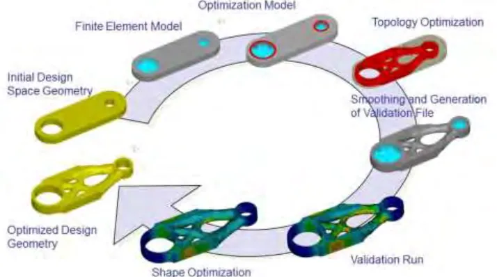
Topological optimization is a method of effectively using material (optimize) layout for a certain design using a calculated mathematical approach. The design should have gone through rigorist analysis from load bearing analysis to stress analysis thus providing multiple parameter, within that parameter is the topological optimization will be conducted without changing any parameter. Engineer can conduct experiment or studies to find out which design is the most cost effective and optimum design structure without losing any vital function of the design.
2
[image:17.612.154.511.139.338.2]topological optimization mainly focus on the determination of the feature of the design. These feature mainly concern the location, hole and the connectivity of all the domain that make up the design.
Figure 1.1: Proses of topological optimization
3
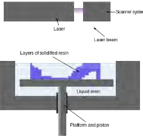
Figure 1.2: Stereo Lithography Apparatus (SLA)
By combining this two idea topological optimization 3D printing create an enormous amount of opportunity and advantage for both designer and manufacturer. 3D printing is the technology of rapid prototyping and combine with topological optimization where by optimizing its sizing, shape and topological structure without discarding its vital part and function will benefit the manufacturer in cost effectiveness greatly and also help the designer develop a master piece design and reduce the time of rapid prototype process.
1.2PROBLEM STATEMENT
The problem that is responsible for this project to arise is as follows:-
i. The cost required to manufacturer the product is expansive.
ii. Material use to mass manufacturer product is too high.
4
1.3OBJECTIVE
The objective of this experiment is as follows:-
i. To perform topological optimization on product to reduce its weight or
mass by using software Hyperworks.
ii. To determine whether or not is it viable to fabricate product of topological
optimization using 3D printer
iii. To evaluate the theoretical data and experimental data.
1.4SCOPE OF PROJECT
This thesis aim is the implement the Topological Optimization process on the Additive manufacturing technology. Using the following process:-
i. Software modelling using CAD CATIA.
Using CAD CATIA for 3D modelling and representation of the
before and after topological optimization.
ii. Software analysis using Hyperworks.
After done creating the 3D model using CAD, the model is then
transfer to this analysis software to be conducted different analysis such as stress analysis or static analysis.
iii. Actual fabricating the CAD model using 3D printer model Kossel.
The Kossel is one of the open source 3D printer provided for this
project. After the analysis is done, its model is then transfer into the 3D printer database.
iv. Compared theoretical data with experimental data.
The theoretical data was provided by the analysis software Hyper
5
v. Report writing.
After all discussion were made and all argument is settle towards
the data, a full report will be provided explaining all the work was done for this research.
1.5GENERAL METHODOLOGY
These are the activities that are needed to be carried out in order to accomplish or achieve the objective of this project:-
i. Literature Review
Journal, articles or even any reading material that are occupy the field of
studies of this project are reviewed.
ii. 3D Representation
Draw the full 3D design using computer aided design Catia to inspect any
flaws before start to print and are able to modify to implement the topological optimization concept on it.
iii. Analysis and Propose Solution
Analysis will be conducted before moving on to the 3D printing, the
analysis will be done using the software hyper works. Hyper works is a software specifically design to be an analysis software. The analysis will continue until the modification on the product is stable and no change in appearance or its micro structure.
iv. Producing product through 3D printing
After analysis process is successful, the 3D representation of the product
6
v. Conduct a string of experiment to determine the mechanical properties
The product produce by the 3D printer will be then submitted to countless
experiment to test its mechanical properties and gather experimental data at the same time.
vi. Comparison between the experimental data and the theoretical data
The experimental data gather through the experiment and the data gather
by the analysis software will be compare to create a viable hypothesis of the properties of the 3D model.
vii. Report writing
7
CHAPTER 2
LITERATURE REVIEW
2.1 3D MODELLING
In the late 1980’s, the need of engineer to hand drawn design, schematic or plan for a project had been greatly reduced (Hazrat Ali, Katsuki, Kurokawa and Sajima 2013). This is because virtual 3D modelling was introduce into the world. At the time of exposure, small and medium size company have already incorporated this revolutionary idea into their ranks. They are easy to access and even more compatible with personal computer making it easier for engineer to perform 3D modelling outside of work. This also means that company are able to cut cost by reducing obsolete department.
8
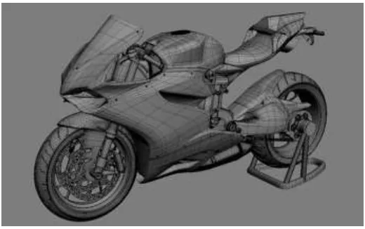
Figure 2.1: Example of 3d model using CAD
3D modelling is define as producing three-dimensional object or surface into a mathematical representation using specialize software either its automatic or manual. These CAD produce such amazing 3D model by first using the available or already drawn 2D design and put it through a process call 3D rendering and use computer simulation. 3D model can also be seen as combine line, shapes and curve surface, than are also form because of combination of point present in 3D space.
2.2 METHOD OF ANALYSIS
9
evolutionary structural optimization and is an extension of the early evolutionary structural optimization ESO.
The optimization employed by BESO is similar to ESO, but at the same time it can also add material that it think it can be beneficial or effective to the structure. It is a more robust method compared to evolutionary structural optimization ESO. Level set method is an applied method of changing the whereabouts of boundary in other word moving boundaries. In some condition, these moving boundaries will come in contact and are join together and a new hole is created (S.Shgaee, M.Mohammadian 2012).
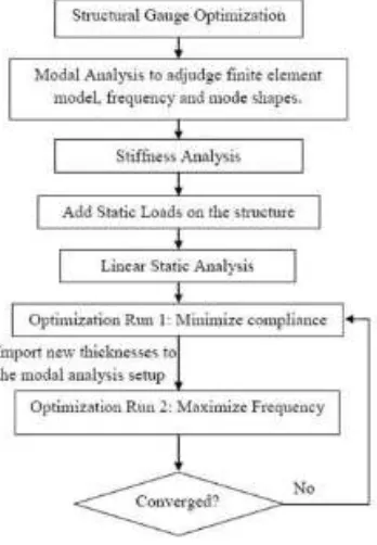
[image:24.612.228.402.438.689.2]In the early year, structural optimization had to only rely on integer values to use as design variable. Bendsoe (1989) was able to come up with brilliant idea, Bendsoe propose a method that will result in a non-discrete solution by varying the design variables in a loop. In pursuing to achieve a non-discrete solution that can come close to a discrete solution method of analysis (mathematical model) used was change to provide a less influence to the intermediate value of the variable. This method was later name as solid isotropic material with penalization (SIMP) (Philip Anthony Browne 2013, D.Brackett, I.Ashcroff and R.Hague 2011).