University of Southern Queensland
Faculty of Engineering and Surveying
Reflector
less
Total
Station
Measurements
and
their
Accuracy,
Precision
and
Reliability.
A dissertation submitted by
Leigh Herbert Coaker
In fulfilment of the requirements of
Courses ENG4111and 4112 Research Project
Towards the degree of
Bachelor of Spatial Science (Surveying)
Submitted: October, 2009
Reflectorless Total Station Measurements and their Accuracy, Precision and Reliability.
By Coaker, Leigh., University of Southern Queensland, 2009.
Despite the vast technological advancements in equipment, the survey industry continues to struggle
with the collection of data relating to inaccessible points. While the introduction of reflector‐less
total stations has meant that inaccessible points can now be measured with relative ease, there are
some questions as to the accuracy and reliability that can be achieved with such equipment.
The object of this study is to determine likely limits for reliability of reflector‐less instruments
especially in relation to measurements with large angles of incidence, but also looking at the
vagaries caused by differing materials and beam divergence. The study has been carried out in
various locations using Trimble S6 and S8 reflector‐less total station equipment to a variety of
surfaces materials and shapes.
This study suggests that angle of incidence of the measurement signal to the surface of the
measured material has a large influence on the accuracy of that measurement. In the search for
accurate survey results from inaccessible points, it becomes necessary to ensure that crucial
measurements are checked as well as having a good understanding of reflector‐less instruments
capabilities.
Faculty of Engineering and Surveying
Courses ENG4111and 4112
Research Project
Limitations
of
Use
The
Council
of
the
University
of
Southern
Queensland,
its
Faculty
of
Engineering
and
Surveying,
and
the
staff
of
the
University
of
Southern
Queensland,
do
not
accept
any
responsibility
for
the
truth,
accuracy
or
completeness
of
material
contained
within
or
associated
with
this
dissertation.
Persons
using
all
or
any
part
of
this
material
do
so
at
their
own
risk,
and
not
at
the
risk
of
the
Council
of
the
University
of
Southern
Queensland,
its
Faculty
of
Engineering
and
Surveying
or
the
staff
of
the
University
of
Southern
Queensland.
This
dissertation
reports
on
educational
exercise
and
has
no
purpose
or
validity
beyond
this
exercise.
The
sole
purpose
of
the
course
pair
entitled
“Research
Project”
is
to
contribute
to
the
overall
education
within
the
students
chosen
degree
program.
This
document,
the
associated
hardware,
software,
drawings
and
other
material
set
out
in
the
appendices
should
not
be
used
for
any
other
purpose:
if
they
are
so
used,
it
is
entirely
the
risk
of
the
user.
Prof Frank Bullen
Dean
Faculty of Engineering and Surveying
Certification
I
certify
that
the
ideas,
designs
and
experimental
work,
results,
analyses
and
conclusions
set
out
in
this
dissertation
are
entirely
my
own
effort,
except
where
otherwise
indicated
and
acknowledged.
I
further
certify
that
the
work
is
original
and
has
not
been
previously
submitted
for
assessment
in
any
other
course
or
institution,
except
where
specifically
stated.
Leigh
Herbert
Coaker
Student
Number:
Q1221241
______________________________________
Signature
______________________________________
Date
Acknowledgements
Firstly I’d like to thank Fleur, my wife, of putting up with me being locked away in the office for
seeming endless weekends, or ‘working’ on weekends while collecting field data. Especially then
coming home (or out of the office) and complaining about how much quality surf I’ve missed out on.
Thanks also to Ed, Geoff and Wayne (the bosses) at Hille, Thompson & Delfos (HTD Surveyors) who
allowed me the use of all their equipment, as well as some of their work time to complete my work.
And finally to my supervisor Albert Chong for his expedient replies to my questions regarding both
technical and non‐technical aspects of my project. Many other staff members at USQ I am also
Abstract ... ii
Acknowledgements ... v
List of Figures ... viii
List of Tables ... viii
List of Graphs ... viii
Glossary ... ix
1 Project Overview ... 11
1.1 Aim ... 11
1.2 The Problem ... 11
1.3 Research Objectives ... 11
2 Literature Review ... 12
2.1 Introduction ... 12
2.2 Background ... 13
2.2.1 Surveying Difficulties ... 14
2.2.2 Accuracy versus Precision ... 15
2.2.3 Types of Errors ... 16
2.2.4 Errors in Reflector‐less Measurements ... 16
2.3 Reflector‐less Total Stations ... 17
2.3.1 Total Stations ... 17
2.3.2 Reflector‐less Measurements ... 18
2.3.3 Reflector‐less Measurement Uncertainties ... 18
2.4 Surveying Techniques ... 20
2.5 Conclusion ... 20
3 Methodology ... 21
3.1 Overview ... 21
3.2 Perpendicular Accuracy ... 22
3.3 Confirmation of Beam Divergence ... 23
3.4 ‘Angle of Incidence’ Measurements ... 25
3.5 Measurements to an External and Internal Corners ... 28
3.6 Measurements to a Curved Surface ... 30
3.8 Measuring a Vertical Surface ... 33
4 Results ... 36
4.1 Results Overview ... 36
4.2 Results of Perpendicular Accuracy ... 36
4.3 Results of Confirmation of Beam Divergence ... 36
4.4 Results of Angle of Incidence Measurements ... 38
4.5 Results of Measurements to Internal and External Corners ... 40
4.6 Results of Measurements to a Curved Surface ... 42
4.7 Results of Measuring to Different Materials ... 46
4.8 Results of Measuring to a Vertical Surface ... 46
5 Discussion of Results ... 49
5.1 Discussion Synopsis ... 49
5.2 Results ... 49
5.3 Accuracy and Reliability ... 49
5.4 Precision ... 50
5.5 Possible Surveying Techniques when Reflector‐less is Not Adequate ... 50
5.6 Ongoing Equipment Trials ... 51
5.7 Different Equipment ... 52
6 Conclusion ... 53
7 Bibliography ... 54
APPENDIX A Project Specification 55
APPENDIX B Raw Results‐ Trimble Geomatics Office (TGO) 59
APPENDIX C Extended Abstract 67
APPENDIX D Project Appreciation (in part) 71
List
of
Figures
FIGURE 1: REFLECTOR‐LESS SIGNAL DIVERGENCE AT AN INTERNAL CORNER. ... 13
FIGURE 2: MINERAL BIN. ANGLE OF INCIDENCE IMPROVED BY DISTANCE FORM BIN. ... 14
FIGURE 3: ACCURACY VERSUS PRECISION ... 15
FIGURE 4: LASER BEAM DIVERGENCE ONTO A SLOPED SURFACE. ... 19
FIGURE 5: TARGETS OF THE BEAM DIVERGENCE TRIAL. ... 24
FIGURE 6: PLAN VIEW, ANGLE OF INCIDENCE TRIAL ... 26
FIGURE 7: MEASURING TO INTERNAL AND EXTERNAL CORNERS ... 28
FIGURE 8: BEAM DIVERGENCE AT AN EXTERNAL CORNER. ... 29
FIGURE 9: TRIMBLE S6, WITH RESECTION CONTROL POINT AND GALVANISED STEEL TANK IN BACKGROUND. ... 31
FIGURE 10: CURVED SURFACE WITH AUTHOR IN BACKGROUND ABOUT TO TAKE REFLECTOR‐LESS MEASUREMENT. ... 32
FIGURE 11: MEASUREMENTS TO GRAIN SILO. ... 34
FIGURE 12: TRIMBLE S8 TOTAL STATION (TRIMBLE, 2007) ... 52
FIGURE 13: ESTABLISHING ACCURATE CONTROL POINTS ON WALL. ... 75
FIGURE 14: REFLECTOR‐LESS MEASUREMENTS TO INTERNAL AND EXTERNAL CORNERS. ... 76
List
of
Tables
TABLE 1: TRIMBLE S6 VERSUS TRIMBLE S8 (TRIMBLE) ... 21
TABLE 2: VARIANCE OF 'ANGLE OF INCIDENCE' MEASUREMENTS. ... 27
TABLE 3: TRIMBLE S6 / S8 PERPENDICULAR ACCURACIES. ... 36
TABLE 4 ; TANK; ANGLE OF INCIDENCE VERSUS ERROR ... 43
TABLE 5: ERRORS INVOLVED IN DIFFERENT MATERIALS ... 46
TABLE 6: SILO MEASUREMENT'S 'ANGLE OF INCIDENCE'. ... 47
List
of
Graphs
GRAPH 1: BEAM DIVERGENCE SHOWN AS ERROR OVER DISTANCE FROM INSTRUMENT. ... 37
GRAPH 2: RESULTS FROM TRIAL 1 'ANGLE OF INCIDENCE' ... 39
GRAPH 3: RESULTS FROM TRIAL 2 'ANGLE OF INCIDENCE' ... 40
GRAPH 4: ERRORS TO INTERNAL AND EXTERNAL CORNERS ... 41
GRAPH 5 : TANK; ANGLE OF INCIDENCE VERSUS ERROR. ... 44
GRAPH 6 : TANK; AVERAGE ANGLE OF INCIDENCE VERSUS ERROR. ... 45
GRAPH 7 : ERRORS WHEN MEASURING TO A VERTICAL SURFACE. ... 47
Glossary
Total Station Surveying instrument combining Electronic Distance Measurement Equipment
(EDME) with a digital theodolite and electronic data recording. Measures horizontal
and vertical angles and slope distance from which horizontal distance is calculated.
Given a known (or arbitrary coordinate), and a bearing, from which to start,
coordinates can then be calculated for new positions.
Prism A glass or plastic reflector that reflects an electro‐magnetic signal back to where it
originated, even though the angle of incidence may change,
3D cords (three‐dimensional coordinates). Coordinates with X,Y,Z values, generally known as
Eastings, Northings and RL (Reduced Level)
EDM or EDME Electronic Distance Measurement or Electronic Distance Measuring Equipment. The
term EDM and EDME are often used interchangeably.
CAD Computer Aided Design. Computer software that greatly reduces the need for hand
calculations and design.
Chainman A survey assistant, used especially where instruments require two people, for
instance levelling, total station set‐outs and pick‐ups (non robotic) as well as helping
to dig and chop as required. Also know as a ‘chainy’.
Theodelite very similar to and the predecessor of the total station. Measures accurate
horizontal and vertical angles which can be used in conjunction with a measured
distance to calculate coordinate data.
reflector‐less total station
forced centring A surveying technique where the tribrach is left on legs (tripod) when
changing between instruments and / or targets. This can eliminate centring errors
due to not using the optical plummet on the tribrach.
Tribrach a piece of surveying equipment that connects the tripod (legs) to the instrument or
prism
Legs the three legged tripod that is used to setup surveying instruments near eye height.
PPM parts‐per‐million. A term to describe the effects of atmospherics on the
measurement signal, both to a prism and reflector‐less. A value of 2ppm indicates
that the atmosphere could cause errors of up 2mm per 1000m. Obviously, as the
distance decrease, so does the error in slope distance.
Angle of incidence
the angle of between the direction of incoming radiation and the normal to the
intercepting surface. (CSIRO, 1992)
Square to the object = normal to the surface = angle of incidence is zero.
1
Project
Overview
An
investigation
into
the
accuracy,
precision
and
reliability
of
reflector
‐
less
Total
Stations.
1.1
Aim
To determine the accuracy, precision and reliability of reflector‐less Total Stations when used in
situations where perpendicular measurements cannot be taken. The project involves the
investigation and identification of potential solutions through the use of surveying techniques and
instrument knowledge to improve the dependability of this technology.
1.2
The
Problem
Reflector‐less (prism‐less) technology is used in a variety of situations to survey infrastructure that is
inaccessible or unsafe, or as a more efficient work practice. While taking a measurement to a flat,
perpendicular surface (perpendicular to the reflector‐less signal) is not perceived as an issue, a
question of accuracy and reliability is raised when taking measurements to a wall with an angle of
incidence of 30 degrees, or 50 degrees.
In addition, measurements to building corners either an internal or external corner could be suspect,
depending upon how and where the signal is reflected. As distance from the instrument increases,
so does the width of the signal beam. How can we, as surveyors, be confident that the returned
signal is from the position at which the instrument is pointed at and not from another object that is
just off line but closer (or further away)?
1.3
Research
Objectives
• Analyse the properties and specifications of various instruments and manufacturers to
identify any differences between instruments.
• Verify that incorrect values can result from reflector‐less measurements where the signal
has varying reflective angles off a flat surface.
• Develop techniques that provide for more reliable use of reflector‐less measurements, as
well as recommend limits for the use of lasers where high accuracy results are expected.
2
Literature
Review
2.1
Introduction
Like many professions, new technology is becoming more influential in many facets of surveying.
Computer technology and CAD packages allow us to design, store and manage more and more data,
while at the same time new technology allows us to collect data faster and mark‐up points in the
field with increasing speed and accuracy.
One such piece of equipment is the reflector‐less (also known as prism‐less) total station. Unlike
conventional total stations or electronic theodelites, which require a prism to return the distance‐
measuring signal, the reflector‐less signal, as its name suggests, does not require a prism but can
simply reflect off almost anything. The main advantage of such reflector‐less instruments is the
ability to measure inaccessible points.
There could be any number of reasons that points are inaccessible, including safety concerns, such
as forgoing the need to enter unsupported ground in underground mine surveying, detail surveys of
busy road intersections where traffic control is undesirable or impossible, or simply finding locations
of jetty piles where access simply isn’t possible.
The problem arises then, of the accuracy that is given by such technological techniques. Whereas
most survey measurements either are or at least can be checked for errors, reflector‐less
measurements, by their very nature of being inaccessible, are very hard to check. How then, can we
rely upon such measurements, especially when high accuracy results are essential, and even simple
checks like using a tape measure between two distinct points is impossible.
The aim of this project is to provide some guidelines outlining the accuracy and precision of
reflector‐less measurements in differing situations and to suggest some techniques to better ensure
the accuracy of measurements made.
2.2
Background
Instrument manufacturers generally supply data sheets for their instruments as part of their
marketing system, which discuss the key features and new innovations as well as specifications on
performance and general information. While this information needs to be truthful, it can also be
quite misleading. Obviously, while data such as size and weight are quite unambiguous, claims of
accuracy can be misleading. For instance, the Trimble S6 Datasheet specifies that the reflector‐less
technology can “Measure quickly and safely without compromising accuracy” (Trimble Engineering
and Construction Group, 2005). Immediately this raises questions about the ability of reflector‐less
technology to reflect the measurement signal solely off the point of interest. This can be challenging
in difficult to access, crowded or confined areas.
So, while both theoretically and practically, the documented accuracies can be achieved, is it really
that simple and reliable in the field? Would a reflector‐less measurement signal reflecting off a wall
at a perpendicular angle of incidence be more reliable? While the measured distance itself may be
correct, is there a possibility that the signal width could cause questions about its reliability in
certain situations? The Trimble S6 has a beam (DR signal) divergence of 20mm over 50m.
Therefore, as shown in Figure 1, over a distance of one hundred metres, the signal from the corner is
40mm wide and 40mm high.
Figure 1: Reflector‐less signal divergence at an internal corner.
This beam size is going to make it difficult to ascertain whether the distance has been taken to the
corner itself or to the wall next to the corner. Conversely, using a normal prism shot to measure the
distance, would ensure that the signal is reflected from the correct position.
Total stations are used to achieve high accuracy three dimensional coordinates that are calculated
by the on board computer through the use of trigonometrical calculations. This is done by the
[image:14.595.148.442.415.580.2]can then be used to calculate relationships between each point in the X,Y and Z planes. Clearly then,
if a distance is measured incorrectly, then the resultant coordinate will also be wrong.
Another technology that is becoming more widespread are laser scanning instruments. They use the
same reflector‐less technology and read thousands of points at a very quick rate. Quoted close
range accuracies of 9mm (Leica Geosystems) are common, with 30mm accuracy for greater
distances and different instruments, and yet these instruments too, are likely to be afflicted with the
same problems as reflector‐less total stations. The difference is that as scanners are automated, a
grid pattern of coordinates are recorded rather than user defined specific points. For this reason,
the question of accuracy of a specific point does not apply, for as in the example above the corner is
not specifically targeted.
2.2.1 Surveying Difficulties
There are a large number of examples of areas where reflector‐less measurements are used at a
distinct advantage. Underground mining uses reflector‐less technology frequently, but generally the
accuracy required is not high. In mining (and other earthworks) situations, a value with 0.05m
accuracy would be sufficient. Mechanical surveys where new prefabricated steel structures need to
bolt to existing steel structures can require accuracies to within millimetres only. There would be
circumstances where even closer tolerances are needed, but these situations require specialist
equipment and personnel and so won’t be studied here.
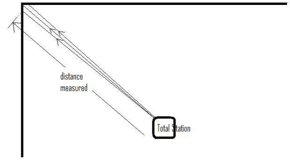
Mineral bins are an example of infrastructure that are difficult to measure and therefore the
accuracy of reflector‐less measurements are questioned. They are generally large and high, and
usually cylindrical. If there is no access to the top, measurements must be taken looking up and so
there is doubt as to what the returned measurement has reflected off. This angle can be improved
though, by moving further away from the bin to measured, if circumstances allow for this.
Figure 2: Mineral bin. Angle of incidence improved by distance form bin.
[image:15.595.114.467.561.690.2]In the case of surveying large diameter pipelines (for instance, gas mainline 600mm diameter 22mm
walls), accuracy sometimes needs to be within a couple of millimetres. Especially when bolt on
flanges need to fit together correctly the first time, such as with expansions to major gas supply
lines. In cases like this, the pipeline will be shut down for a minimal time only, and the expansion
pieces need to bolt in without further welding or cutting. If using reflector‐less measurements,
there needs to be no doubt that the measurements are correct, even with a lot of clutter to measure
around, and the fact that measurements will sometimes need to be taken to a curved surface and
not at a perpendicular angle.
Traditional survey methods generally require access to any points that need to be measured. One
exception would be to record a vertical and horizontal angle to a single point from at least two
different positions. The coordinates could then be calculated. While this is possible, it would also be
time consuming, especially if there were a large number of hard‐to‐see points. This need‐to‐access
in the past, would have likely caused its own problems such as getting access to scaffolding or an
Elevated Work Platform (EWP), but this access to points would also allow for measurements to be
done using conventional means, as well as independent check for accuracy to be made.
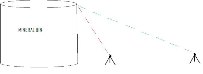
2.2.2 Accuracy versus Precision
When used in general conversation, the words accurate and precise are generally interchangeable.
In surveying however, accuracy and precision refer to separate results. Accuracy refers to the
result’s closeness to the true or accepted value. Precision refers to the spread of results for a
number of measurements. For instance, six independent measurements of a line (using a single tape
measure) could result in six different distances. These values may vary either by very little or by a
lot. This is precision. If those results were close to the accepted value then they would also be
accurate, but if the tape had been stretched, the results could be far from the accepted true value.
Then, the given result could be said to have high precision but low accuracy.
Accurate and Precise Precise but not Accurate
[image:16.595.131.529.561.716.2]As shown in Figure 3, many ‘measurements’ do not necessarily ensure a more accurate result.
Therefore, repeated measurements from a reflector‐less total station does not automatically
increase the accuracy of the result.
2.2.3 Types of Errors
While survey observations can be highly accurate, observations are never exact, and therefore
always contain some errors. (Wolf & Ghilani 2001). In surveying, there are three types of errors,
known as systematic errors, random errors and gross errors (Dept of Civil and Environmental
Engineering and Geodetic Science, 2001). Generally, they have different causes, and produce
different results.
Gross errors are blunders, simple mistakes that should be found using checks during a survey. They
can be caused by the surveyor, the chainman, the instrument settings and other variables. Often
they occur through carelessness, an incorrect point being measured, hand recording errors and so
on. Gross errors can be either big or small and are non‐cumulative (Dept of Civil and Environmental
Engineering and Geodetic Science 2001).
Systematic errors are a procedural error that can be mathematically modelled and therefore
corrected (Dept of Civil and Environmental Engineering and Geodetic Science, 2001). For instance,
measuring using Electronic Distance Measuring Equipment (EDM or EDME), with the incorrect prism
constant will cause every point to have the same error, either toward or away from the instrument.
Such errors can be remedied post survey through computer software and can be avoided using
check measurements (to control points) and care when changing between prisms or types of
measurements. Other systematic errors include level bubble out of adjustment on instrument or
prism pole, level staff that has not been fully opened. Systematic errors can be either big or small
and can be cumulative.
Random errors are the reason that measurements are never exact. They are small non‐cumulative
errors that occur as part of the measuring process. When reading a tape measure, deciding if the
reading is 4.523m or 4.522m is a random error, as is instrument setups using optical plummets,
pointing of total station to the centre of prism and the holding of prisms truly vertically. Random
errors are difficult to minimise, since they cannot be stopped from occurring, we can overcome
them using techniques such a minimising instrument setups or making a number of readings and
taking the average.
2.2.4 Errors in Reflectorless Measurements
Reflector‐less measurements, like all measurements, can have gross, systematic and random errors.
Gross errors cannot be ignored, especially for reflector‐less errors. Because reflector‐less
measurements by their very nature are likely to be inaccessible, it is often difficult to perform check
Especially if the flange is close to the ceiling, we cannot be sure that the signal is off the flange or off
the ceiling itself. If we had access to the flange, we could easily check the distance with a tape
measure, to prove we have the correct distance. Without access, it could become a difficult task to
prove.
Reflector‐less instruments are no more prone to random errors than any other total station
measurement, setup errors being an obvious one. This being the case, reflector‐less measurements
should have no more error than EDM measurements.
Normally systematic errors can be difficult to find if they occur. This is possibly exaggerated with
reflector‐less measurements as there is usually difficulty in getting a check measure. One problem
with the reflector‐less signal is that it may not be co‐incidental to the observed target as indicated by
the sighting crosshairs (Leica Geosystems). If this is the case, calculated positions from incorrect
distance and angles could be incorrect in any direction depending upon how the object is measured.
Theoretically, by averaging ‘face left’ and ‘face right’ observations, this error should be removed, but
it would depend on what is being measured.
Another factor to consider is the size of signal. If measurements are taken from long distance, it is
hard to ascertain where exactly the signal is being reflected from (Key & Lemmens, 2005).
2.3
Reflector
less
Total
Stations
2.3.1 Total Stations
A Total Station is an electronic surveying instrument that combines Electronic Distance Measuring
Equipment (EDME) with an electronic theodelite and a computer. The electronic theodelite simply
measures angle on two planes, the X‐Y plane (horizontal plane) and from the X‐Y plane (vertical
plane). The EDME (or EDM) measures the distance (slope distance) to a prism to which it is pointed,
while the on‐board computer stores and calculates a large number of values form these three
measurements.
EDM measurements are taken using laser (Light Amplification by Stimulated Emission of Radiation)
technology, developed in the 1960s (Key & Lemmens, 2005). There are two types of measuring
signals, ‘phase shift’ and ‘time of flight’ (TOF) also known as ‘pulse’. Phase shift is considered the
most accurate and has a narrow beam but has the disadvantage of a small range. TOF conversely,
has a greater distance but a wider signal, resulting in a reduction of accuracy (Key & Lemmens,
2005). Only a small amount of energy is required to measure a distance to a prism using this
technology.
As the name suggests, ‘time of flight’ measures the distance by directly converting the time taken for
the laser signal to return to the instrument from the prism, while phase shift uses a set of different
Using trigonometry, the computer uses the measurements to calculate horizontal distance, bearings,
vertical distances, 3D coordinates, inverses (bearing / distance between points), real‐time distance
to a coordinate and a number of other values. Later total stations can also give cut / fill values to
designs and calculate areas.
The electronic theodelite, which has evolved from the optical theodelite, uses two graduated plates
to determine a horizontal angle and a vertical angle, usually from zenith. These values are output via
a LCD screen. Bearings can be calculated simply by knowing the true instrument setup position as
well as one other point which is used to set the bearing (backsite).
Before EDME became available, chains (long steel measuring band, usually 50m long) were used to
measure distances which were both slow (calculations were required to adjust the distance for slope
and for sag of the steel band) and required hand recording. EDME, along with digital data recorders
allowed for vastly quicker and easier measurement, storage and revision of the data.
2.3.2 Reflectorless Measurements
Reflector‐less measurements have only quite recently become in‐built into total stations. They can
allow for extremely easy safe and accurate measurements provided they are used correctly, and
users are aware of their limitations. Range of these instruments have increased and some now
exceed 1500 metres (Topcon Australia, 2009) to white targets or several hundred metres to natural
darker targets. This is generally quite sufficient as at ranges of several hundred metres, it is difficult
to accurately point the instrument at its target and beam divergence can become a problem.
In the mining industry, at times large ranges could be desirable to monitor pit walls but for the day‐
to‐day workings it is not required.
Reflector‐less EDMs requires a high‐energy laser pulse (TOF method) to enable it to reflect off any
surface it is aimed at. It is the high energy level of the laser that allows the detection of the reflected
energy. This high energy output can cause a hazard (to eyesight) in some situations where there are
pedestrians in close proximity or where the telescope is used and the surfaces are reflective or
prisms are close‐by (Leica Geosystems, 2005).
2.3.3 Reflectorless Measurement Uncertainties
There are two main causes of error and unreliability in the use of reflector‐less total station
measurements. These are caused either by beam divergence or reflector uncertainty. Reflector
uncertainly is a situation when the laser beam is reflected off something other than what it was
supposed to. This could be either in front or behind the desired object. This can only be avoided
through care, checks on measurements, and instrument knowledge.
One of the main concerns with the accuracy of reflector‐less total stations is beam divergence. As
the size of the laser spot increases with distance from the instrument, so the accuracy of the
measurement becomes less reliable. For instance, trying to measure a 50mm diameter pipe from
50m away would be difficult if the laser ‘footprint’ at this distance was 100mm diameter as is the
signal from the Topcon GTP8205 (Leica Geosystems). It would not be reliable because there is no
certainty that the signal reflected off the pipe itself rather than something in the background or even
a combination of the two.
It is also noted that depending on the characteristics of the reflecting surface the “waveform of the
laser beam scattered back by the surface may be a rather distorted version of the emitted pulse”
(Key & Lemmens, 2005). This distortion can lead to uncertainties in the distance measured and can
either give an erroneous result or no resultant distance.
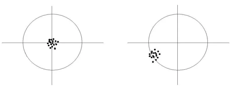
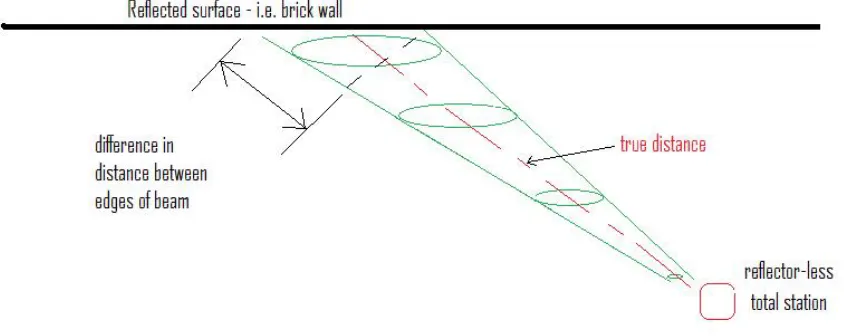
Key & Lemmens (2005) also suggest that as the beam divergence increases, so too does the time
range of the reflected signal off a certain plane. As shown in Figure 4, there is a difference in
distance between the edges / centre of the laser beam, which can translate to a variation in the
measured distance. Although, this would become negligible when the plane being reflected off
becomes perpendicular to the laser beam.
Figure 4: Laser beam divergence onto a sloped surface.
The greater the laser beam divergence, the larger the size of the laser ‘dot’ on the surface. As shown
in Figure 4 above, there are two parts to the errors caused by laser beam divergence, the size of the
‘dot’ on the reflected surface and the angle of incidence with the surface. Unfortunately, by moving
the instrument to a more distant position to lower the angle of incidence, also has the effect of
increasing the size of the laser ‘dot’. The ideal would be to setup the instrument at a perpendicular
angle for each measurement. This would allow for a more reliable measurement but this is often
either impossible or impracticable.
There a number of common total stations in Australia, which include Topcon, Trimble and Leica,
each having their own specifications. When it comes to reflector‐less specifications in the field, as
[image:20.595.92.515.371.539.2]Geosystems), the laser beam divergence varies greatly between instrument manufacturers, with the
laser ‘spot’ varying in size from 9x28mm to 100x110mm at a distance of 50m from the instrument.
Obviously, with such a variation, different instruments could be used in some applications while
others would become unreliable.
2.4
Surveying
Techniques
Although there is not a lot of data available indicating specific techniques for the use of reflector‐less
total stations, a Trimble Support Note (Haefeli‐Lysnar, 2007) gives several techniques on the use of
this technology in specific cases. Several of the techniques are based on calculations from indirect
measurements. These include:
• The measuring of two intersecting wall planes to calculate the corner.
• Using the instrument’s ‘max range’ and ‘min range’ to ensure there is no interference from
other objects.
• Distance / angle offset by measuring a distance to centre of an object and using an offset to
determine the edge position.
Non calculation‐based methods include:
• Measuring in both face‐left and face‐right to “cancel out the effect of the slope caused by
[an] oblique angle” (Haefeli‐Lysnar, 2007)
2.5
Conclusion
Notably, there appears to be a significant lack of research completed into the reliability of reflector‐
less total stations in day‐to‐day surveying applications. While some information was found, the
accessibility to these resources was limited. In most cases, abstracts were readily available but full
papers were harder to come across.
Nevertheless, there is a good amount of data to support the quality of the instruments that are
being manufactured, and it seems that some of the accuracy problems have not been quantified
mainly because there are so many different situations in surveying. As field conditions alter, the
quality of reflector‐less results also changes.
Despite the fact that the instruments themselves may be as accurate as the manufacturers claim, it
is how they are used that will ultimately ensure that the final results are within the surveyors stated
tolerances. To this end, this research aims to offer practical recommendations for the use of
3
Methodology
3.1
Overview
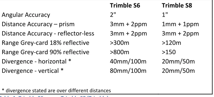
To begin, two instruments will be used for the investigation, a Trimble S6 and a Trimble S8 which is a
newer version of the S6, and only introduced late in 2007. While quite similar, both in appearance
and use, the S8 has increased accuracy to a prism and while the reflector‐less ‘DR’ mode has the
same accuracy specifications, the beam divergence is smaller.
Trimble S6 Trimble S8
Angular Accuracy 2" 1"
Distance Accuracy – prism 3mm + 2ppm 1mm + 1ppm
Distance Accuracy ‐ reflector‐less 3mm + 2ppm 3mm + 2ppm
Range Grey‐card 18% reflective >300m >120m
Range Grey‐card 90% reflective >800m >150
Divergence ‐ horizontal * 40mm/100m 20mm/50m
Divergence ‐ vertical * 80mm/100m 20mm/50m
* divergence stated are over different distances Table 1: Trimble S6 versus Trimble S8 (Trimble)
Parts‐per‐million (ppm) is a measure of accuracy explaining that the expected accuracy is accurate to
one millimetre per one million millimetres (any unit), so an accuracy of 2ppm is 2mm per 1000m.
Hence at a distance of 100m, an accuracy of 2ppm calculates to 0.2mm and is therefore insignificant.
The study of the accuracy of reflector‐less instruments will be broken down into several parts.
Firstly, confirmation of the accuracy in the instruments’ specifications needs to be established, both
for the prism and reflector‐less measurements. There then will be a number of tests carried out to
determine how accurate the reflector‐less instrument is in a number of situations.
A number of tests have been designed to simulate different field applications and should give a good
indication as to how reflector‐less results vary. These include:
• Measurements to a perpendicular plate; to check accuracy of reflector‐less instrument.
• Measurements with a varying ‘Angle of Incidence’; to see what difference is generated by
measurements to a non‐perpendicular target.
• Direct measurements to an external corner; to establish what accuracy results.
• Direct measurement to an internal corner; establish from where the signal is reflected
from.
• Measurements to a curved surface, to determine how accurately a laser can measure to
it; similar to measuring with a varying ‘angle of incidence’.
• Measurements to different materials to prove that reflector‐less measurements are
accurate to various common materials.
• A check of long distance measurements to verify the stated accuracy over a range of
[image:22.595.74.416.232.388.2]• Experiment with the effect of angle of incidence when measuring up a tall object.
• To establish the size of the reflector‐less signal, measure to a bolt head from varying
distances to ascertain what distance will allow for accurate measurements to a small
target.
Many of the ‘true’ measurements were taken using the same instruments as the tests conducted to
establish the reflector‐less accuracy. While the S8 has better accuracy specifications than the S6
using a prism, and so was used as the ‘true’ value, even the 3mm + 2ppm that is achievable with the
S6 (and used to check the distance established by the S8) the aim of this study is to establish errors
with the reflector‐less technology. As instrument measurements of this type are only accurate to
several millimetres due to both the instrument and setting up (random) errors, small errors of up to
three millimetres will be ignored in most cases.
Forced centring was used where possible to eliminate the errors caused through the use of optical
plummets. When forced centring wasn’t able to be used, such as in the case where a number of
setups was used to establish true coordinates, resections were used to reduce the effects of centring
error.
Effects of atmospheric corrections, although entered into the instruments for PPM (parts‐per‐
million) corrections, will have no effect if the measurements are all taken at the same time. This is
because the instrument corrections will be the same for both prism measurements and reflector‐less
measurements. Both instruments though, need to be set to the same correction.
3.2
Perpendicular
Accuracy
Before starting various tests on accuracy, it must be proved that the results from a simple,
perpendicular measurement gives the accuracy that is stated in the instruments specifications.
From this model we can show any divergence from the instrument accuracy specifications.
Simply, a distance was measured using a prism to a white target, and then again using the reflector‐
less signal. This was then be repeated a number of times in increasing distance sizes between 10m
and 100m. The object was a painted concrete tilt‐panel building and a number of measurements
were taken to it at an angle of incidence of approximately zero. A distance was then read several
times to check for deviation, both using reflector‐less EDM and using the flat 2mm prism. The
distance was measured from four different distances, that have a close proximity as longer distances
would not be used to gather accurate measurements. The distances from instrument to wall are
11.3m, 40.5m, 79.2m and 103.6m.
3.3
Confirmation
of
Beam
Divergence
The intention of this trial was to establish by field observation to what distance a small size object
could be measured to before the beam divergence began to give inaccurate results. In this case, due
to its resemblance to field operations, a bolt head was measured to. By starting at a close range,
and progressively moving further away, a range threshold could be established for accurate
measurements to small targets.
The true distance was first established by measuring the computed horizontal distance to a flat
prism placed on the wall behind the bolt head and subtracting the distance that the bolt head
protruded from the wall that was measured using a steel rule. This is done for each instrument
setup as the distance is increased between instrument and target. Then, using reflector‐less
measurement mode, the distance was measured to the bolt head itself. In this way, once the
reflector‐less measured distance does not match the ‘true’ distance subtract the bolt protrusion
distance, we can affirm that the ‘measurement beam’ divergence has negatively affected the
accuracy and reliability of the reflector‐less measurements.
The first trial was a failure because even from a distance of just ten metres, the ‘bolt head’, that
needed to be covered to eliminate a hole, did not measure correct distance; that should be the
distance to the wall subtract the protrusion distance. This is possibly due to the fact that the hollow
‘bolt head’ was covered using black electrical tape. After this failure which was done to a ‘bolt head’
with a ten millimetre diameter, the methodology was replicated using two created bolt heads of
different sizes. For all of these beam divergence trials, the instrument has been placed at right
angles to the object. With this approximate zero angle of incidence, any errors associated with non
Figure 5: Targets of the beam divergence trial.
The two bolt heads were chosen randomly, to represent a range of real world problems. The first
had a diameter of twelve millimetres, and the second had a diameter of twenty two millimetres.
Both the bolt heads, and the background were painted white, to ensure neither the target (bolt
head) nor the surrounding background had any reflective advantage. The protrusion distance was
measured from the backing plate to know when the distance was being accurately measured to the
bolt head and not to the backing plate. The measured distance should be the distance to the
backing plate with the protrusion distance subtracted. In the case of the twelve millimetre bolt
head, the protrusion distance was thirty two millimetres from both the backing plate and the
separate white target. The twenty two millimetre bolt head had a projection distance of twenty
nine millimetres.
Logically, in relation to beam divergence, as distance to the object increases, so too will the beam
divergence. Hence as the measurement beam width increases, an increasing amount of the
returned signal will be from the background and not from the target, in this case a bolt head. For
[image:25.595.146.446.65.470.2]object and moved closer incrementally to determine at what distance from the target the correct
measurement was made.
3.4
‘Angle
of
Incidence’
Measurements
The ‘angle of incidence’ measurements were probably the most important, as these results replicate
closely what is a common surveying measurement. The reflector‐less measurement of an object
from a position that is not at right angles to the surface of the object. There is going to be several
possible errors caused in these situations. Firstly, the alignment of the measurement signal with the
optical alignment would make the measurement signal reflect off a point that is not the same as the
point that is lined up using the eyepiece. Secondly, and a problem that would increase the error as
distance increases, is the size of the measuring signal and the effects of beam divergence.
This trial was carried out using both the Trimble S8 and the Trimble S6 instruments in a private car
park area, against an extended brick walled building. Firstly, ink marks were made on the wall at
approximately five metre intervals that were then measured accurately using the 1mm flat prism.
This was done from a distance of 21 metres, and from a point midway along the wall so as to negate
any effects of errors caused by angle of incidence. As a check for the control data, these points were
also measured using the S8 reflector‐less mode. A second control point was also established closer
to the wall from which the angle of incidence trial measurements would take place. This second
control point was placed just eight metres from the wall.
Using forced centring to exclude optical plummet errors, the instrument was setup on the newly
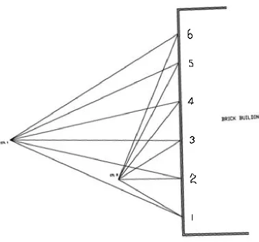
established control point from where the reflector‐less measurements were taken. Measurements
were taken using both ‘face‐left’ and ‘face‐right’ configurations to determine any differences caused
Figure 6: Plan view, Angle of Incidence Trial
As a check, a separate instrument setup was completed to take prismatic measurements parallel
along the wall (at a parallel offset of 88mm) to ensure the distances measured from the first
instrument setup were correct in the east – west orientation (see Figure 6 above).
A technique (Haefeli‐Lysnar, 2007) to be proved is the use of ‘face left / face right’ averaging. This
assumes that the distance measured to an object at an angle of incidence will cancel out any errors
using two faces. This could be correct if the reflector‐less signal is not coincidental to the line‐of‐
sight as per the instrument crosshairs, but if the error is due to the width of the measurement signal,
it may not make any difference.
There was need to redo some of these measurements again mainly due to the large ‘angle of
incidence’ increments but also to corroborate the results. As such, a new site was chosen, both to
try and increase the distance between instrument and wall and to use a different surface as the
reflected material. A smooth concrete tilt panel building was used for this second angle of incidence
[image:27.595.82.460.97.451.2]The main differences between the first and second ‘angle of incidence’ trials is the distance between
the instrument and the wall, the wall material (smooth concrete as opposed to clay brick), and more
measurements, ensuring a smaller variance between successive angular measurements. This was
intended to more clearly show where the reliability and accuracy begins to erode.
Measurements were taken using both ‘face‐left’ and ‘face‐right’ with both the Trimble S8 and S6
instruments to examine if there are any differences caused by measurements on both faces. The
aim of this is to effectively establish whether there are any errors brought about by the non‐
coincidence of the optical crosshairs and the reflector‐less ‘beam’.
The targets were marked on the wall at approximately equal distances of roughly three metres apart
and the instrument was setup in an arbitrary position 18.8 metres from the wall. A backsight angle
was taken and recorded to ensure nothing had moved throughout the trial and checked once all the
measurements had been taken, and also to allow (using forced centring) the setup of both
instruments in the same position and orientation. This allowed for the simple comparison of results.
With these dimensions, the second ‘angle of incidence’ trial has a variety of different angles, both to
the left and right of square (angle of incidence of zero). These angles can be seen in the table below.
Angle of Incidence
decimal degrees
‐47.4 ‐38.6 ‐27.4
0.5
9.1
16.7
23.5
27.2
37.6
41.9
45.8
49.1
52.1
54.7
Table 2: Variance of 'Angle of Incidence' measurements.
The table below shows a range of measurements with an angular range of 102⁰. This ranges from
47⁰ right of square to 55⁰ left of square. This seemed to be an adequate range considering the
[image:28.595.237.348.365.613.2]3.5
Measurements
to
an
External
and
Internal
Corners
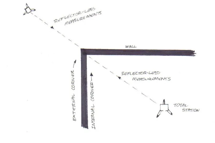
An ‘external corner’ is a corner that is viewed with the walls running away from the observer. An
‘internal corner’ is one that is viewed with the walls running toward the observer (Figure 7).
Figure 7: Measuring to Internal and External Corners
The problem with measuring to corners is the ‘beam’ (signal) width and divergence. As the distance
from the instrument increases, so does the beam width, which at corners can cause a range of
distances returned to the instrument from one measurement. With the S8, at a distance of 50m, the
(claimed) 20mm divergence would give a distance range due to beam divergence of approximately
14mm. However with the S6, if shooting to a horizontal corner, as in a corner found between ceiling
and wall, the 40mm divergence at 50m would equate to a range in received distances of
approximately 28mm.
Like the measurements to an external corner, internal corners cause much the same problem but
instead of measuring long as per the external corner, measurements range from accurate to shorter
than the true distance. See Figure 8: Beam Divergence at an external corner.
According to Haefeli‐Lysnar (2007) one technique in surveying corners is to get two wall shots for
each wall that intersect to create a corner and use those lines to generate a corner point. While this
is a viable survey technique, it can just as easily be carried out post‐survey using a computer
package. It also assumes that each wall is straight and that the angle of incidence that is needed to
get each measurement has no significant errors. [This is explained fully later in the study]. To this
end, the trial was carried out to see how the corners affect the accuracy of the measurement as the
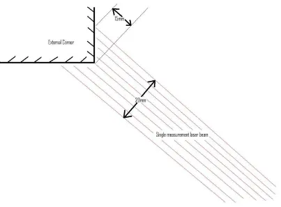
[image:29.595.92.441.187.419.2]The effect of increasing distance between object and instrument is caused by beam divergence; as
the distance from the corner increases, the beam width increases and it follows that the distance
between the shortest and longest signals returned to the instrument also increases. This is shown
on the diagram below (Figure 8).
Figure 8: Beam Divergence at an external corner.
Distances to an internal corner are similar, as the distance between instrument and corner increases,
so too does the distance between the longest and shortest returned signals for each measurement.
Obviously, with a wider signal, as distance between instrument and object increases so too does the
distance increase between the centre of the measurement signal and the edges. Assuming the
centre of the measuring signal is at the point of the corner, any width of that signal must be closer to
the instrument which obviously means that those parts of the signal will return quicker and give a
reading that is closer than it truly is.
The measuring of external and internal corners was done on tilt panel building corners, with the
internal corner being silicon sealed and therefore not having a sharply defined corner. The external
corner however was concrete and a well defined corner.
To test the corner measuring abilities, which relate to beam divergence and width, a number of
measurements were taken at increasing distances from the corners. The corner was measured
accurately first using a flat prism which had been stuck to the corner of the wall. Then, from the
[image:30.595.88.491.167.464.2]hundred millimetres below the prism. The wall had been previously checked for verticality and only
horizontal distance measurements were logged.
One problem encountered at the beginning was where the reflector‐less observation was reflecting
off the prism, even though it did not seem to be even close to the optically aimed instrument. This
happened where the internal corner was ‘behind’ the prism set up for the external corner. In fact,
the prism was approximately 250mm offline to the reflector‐less target. This was a problem even
when the instrument was set up only ten metres away. Simple to solve, the prism was removed and
the measurements redone.
The measurements were taken at a range of distances from the corners, approximately every ten
metres but randomly positioned. The distances were; 10.3m, 23.0m, 32.6m, 40.6m, 50.1m, 59.3m,
67.2m, 78.9m and 88.9m. Although the distances didn’t approach the maximum range of the S6
instrument, distance inaccuracies had already become discernible through the field booking.
Additionally, if accurate measurements are being pursued, then the distance should be kept to a
minimum.
3.6
Measurements
to
a
Curved
Surface
Curved surfaces can cause accuracy problems when measuring distances using reflector‐less
technology. This is due to the difficulty of determining where the signal ‘point’ is being reflected
from and whether that point is the same point as is sighted through the crosshairs of the eyepiece.
This error is similar to the ‘angle of incidence’ error that is effected by measuring to a point on a
surface that is not perpendicular to the measurement signal.
A trial to test the accuracy in these cases was carried out on a galvanised steel water tank with a
radius of 5.2 metres. Survey points were marked around the tank at intervals of approximately one
metre. The survey marks were then accurately coordinated using a +1mm prism constant flat prism
(reflector). To negate the effect of accurately measuring to a prism at a high angle of incidence, two
setups were used in this process, both resections and at differing angles to so that measurements to
the prisms on the tank were at a larger angle of incidence. In this way, each measurement was
taken at an angle that is close to perpendicular to the tanks surface. One point on the tank was
measured twice, once from each setup as a check to ensure both the quality of control setup, and of
the measurements with the flat prism.
Figure 9: Trimble S6, with resection control point and galvanised steel tank in background.
Control was established using two arbitrarily placed tripods (with circular prism) that remained in
place for the entire trial. These points were coordinated at the beginning, and were then used as
resection base stations for the other setups. Each of the other setup points, including the setups to
establish the true coordinated points were done in this way. Resections have the advantage of
eliminating optical plummet error, so that each setup point is as closely related to each other point
as possible. The Trimble S6 instrument used in this trial calculates error ellipses for its position with
the use of redundant measurements. In each case the error ellipse was at most one millimetre.
[image:32.595.72.527.71.414.2]
Figure 10: Curved surface with author in background about to take reflector‐less measurement.
Four setup points were used for this trial, with an increasing distance between tank and instrument
from 10m, 16m, 30m and 44m. These distances are from instrument setup point to closest part of
the tank. Clearly, the distances between instrument and tank changed even within a single
instrument setup due to the radius of the tank. This difference, of up to four metres, has been taken
as inconsequential due to both its small magnitude as well as the range of distances measured using
[image:33.595.76.459.69.584.2]A number of setups were used both to gather a large dataset of information with a good range of
‘angle of incidence’ values and to determine whether increased distance from the reflected surface
was to make a difference.
3.7
Measuring
to
Different
Materials
This was simply a trial to prove whether different surfaces cause any errors in the distances
measured using reflector‐less technology. These results were simply a collation of results from
various other trials, where measurements were taken to different materials, from angles that were
close to perpendicular between measuring signal and object. Materials included brick, galvanised
steel and concrete.
The aim here is to look at structural materials only as (in general terms), the roughness of stone and
other natural materials, even if they are used for construction, would preclude sub‐centimetre
accuracy.
While the results of this collation focuses upon measurements taken at right angles to the object’s
surface, it doesn’t take into account any differ