International Journal of Innovative Technology and Exploring Engineering (IJITEE) ISSN: 2278-3075, Volume-8 Issue-6, April 2019
Abstract:The future, in the field of communication, the change will be tremendous, there will be a considerable development. Due to its promising and wide variety of techniques the FSO (Free Space Optics) has taken a colossal attention. Reason for its appeal is because of the time of deployment and the cost of alimentation. Irrespective of its advantage it has its downside because there will be a downfall in the signal durability due to the meteorological influencelike mist, snow,haze etc. Also due to its line of sight communication it also endures issues due to interference like birds, motion of earth, scattering etc.In the paper, we focused mainly on the intensity and its attenuations are calculated and accordingly the Q factor power and BER are calculated. These parameters will be calculated with BER Analyzer and the modulator used is MZ modulator. This examination is done in a simulation tool named OptiSystem and was improved by Optiwave.
Index Terms: Free space optics, Meteorological effects,Quality Factor, BER Analyzer, and Optisystem.
I. INTRODUCTION
The technology has been accelerating beyond our imagination. When it comes to telecommunication it is swift and at the same time the users are also growing faster. This leads to the shortage of the bandwidth. However free space optics made it convenient as it is able to provide higher bandwidth, which support for higher quality of communication [1]. Besides it has advantages as license free communication, advance security, free from jamming and its effortless stationing. This system has the capacity to be able to conduct speeds till 1 Gb/s [2]. However due to its communication is through air factors like meteorological influences and hindrances.
For the transmission of information or data over free space at larger data rates it will be easier and more dependable [3]. These free space optics commonly operates at higher frequencies which is Tera Hertz that is at infrared wavelengths and by delivering higher bandwidths it goes through a number of limitations such as signals scattering and performance will be diminished. The frequencies employed here are higher the change in climate has its effect on the transmission when compared with effects of low frequency signals [4].
The attenuation models used are endorsed by International
Revised Manuscript Received on April 05, 2019
K. Sony, Asst Professor Dept. of ECE, KoneruLakshmaiah Education Foundation, Vaddeswaram, Guntur District, India.
L. Sreekar, Student,Dept. Of ECE, KoneruLakshmaiah Education Foundation, Vaddeswaram, Guntur District, India.
Y. Sri Krishna, Student, Dept. of ECE, KoneruLakshmaiah Education
Telecommunication Union [5]. And the models endorsed areCarbonneau model and Japan model.However these models were useful at low rain fall areas, so countries like India where having more rainfall which is at tropical localities these were unable to predict, in order to overcome this problem there are two more models were introduced. One is Samir model and the other one is Suriza model. For example [6] for a rain intensity of 3.26 mm/hr the attenuations for the above two models are 2.37, 3.32 respectively, for lower rainfall rates. On the other hand when we compare with larger rainfall these models have more attenuation than the other models. Overall in the paper the four models are compared along with two different generators which are NRZ and RZ pulse generators. Alongside with these models, by using which generators we are capable of getting better attenuations and quality factor which bring out the best usage at conflicting conditions.
II. FACTORSEFFECTINGFSO
FSO link performance mainly depends on meteorological conditions [7] and physical characteristics of the area of installation. Generallyfactors like beam dispersion, atmospheric absorption terrestrial scintillation, pollution, instability in wind, motion of earth, solar interface, obstruction for line of sight. The factors mentioned above leads to greater BER (bit error rates). To overcome these different models were used in the paper for improved results. Alsowavelength of 1550nm gives better results than 830 nm, 850 nm and 1310 nm.Since wavelength of 1550 nm is capable of transmitting larger powers than the remaining wavelengths.
III. MODELINGANDSIMULATIONSETUP
The software tool used in the paper is Optisystem which is developed by the Optiwave systems. For this analysis we have designed an Optical system for communication by using various components to help create a better model. In this tool a component library is present which consist of all types of components. Through these components a system has been constructed which suits for the design for a covert application. The design process is given as
For any communication a transmitter and a receiver are must, in order to form a transmitter and a receiver with the help of components PRBS (Pseudo-Random Nit Sequence) Generator, NRZ (Non-Return to Zero) Pulse Generator, CW (Continues Wave) Laser, MZ (Mach-Zehnder) Modulator when installed together the
Evaluating the performance of FSO links using
various attenuation models
or connected to FSO channel and the receiver comprise of Photo Detector PIN, Low Pass Bessel Filter and 3R Regenerator. Now coming to the components [8] used first we stumble upon PRBS-Generator, this generates a binary sequence which are truly arbitrary signals and the data rates included in this setup are 1.25Gbps. Secondly we come across NRZ or RZ pulse generator, these encodes the signal information which helps in mixing with the Carrier signal.
Later for the data signal modulation with a covet power for higher data rates a laser source is needed, so a CW (continuous wave) Laser is used and this setup is regulated at 1550nm, we are using 1550 nm because less than that there will be scattering of the signal and if more than 1550nm the absorption will be more and as we use laser it becomes unsafe for living beings. Finally in the transmitting end we use MZ (Mach-Zehnder) Modulator it helps to modulate signal from NRZ generator, this MZ Modulator also helps for the controlling of the optical wave amplitude and makes the signal ready for the sending to the FSO channel, this FSO channel acts as the main part since the entire simulation performance is varied just by changing the parameters of the FSO channel. In this we have kept 1km as the range for the channel and simulated at different powers. The Attenuation s are also change but the beam divergence angle is set to 2mrad, the Transmitter aperture diameter and Receiver aperture diameter are 5cm and 10 cm respectively.
[image:2.595.316.549.48.227.2]Finally coming to the receiver part at first we come across a photodetector PIN, which helps to detect photons and is able to convert from optical energy to electrical energy, later on this signal is sent to Low Pass Bessel filter, this filter helps in granting the permission for getting the desired signals, which means the frequencies which are greater than the cut-off frequency will not be allowed through the filter. The cut-off frequency is kept as 0.75*Bit rate Hz. Moving on to the next component that is 3R Generator, it helps in producing of reference signals. Finally these signals are passed on to the BER (Bit error rate) Analyzer, and the desired outputs are achieved through BER Analyzer. The architecture is as exhibited for Fig. a for NRZ and for Fig. b for RZ
[image:2.595.317.548.407.636.2]Fig.a FSO NRZ simulation setup
Fig. b FSO RZ simulation setup
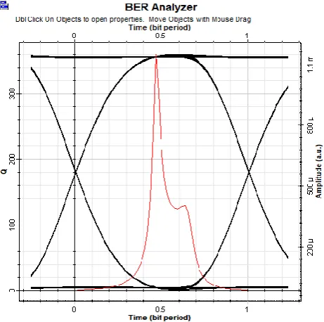
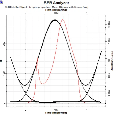
Moreover the circuit analysis is done by keen observation of the Eye Diagram [9]. From the eye diagrams beneath we can observe a red curve which indicates the variation or fluctuation of Q-factor and the black curve serve as the eye diagram. From the Fig. c and Fig. d we can clearly say that by increase in rain intensity there is a decrease in the eye opening which means there is a decrease in the efficiency of the system by increasing the intensity of rain, further more it is noticed that the Q-factor also decreases with an increase in rain attenuation.
[image:2.595.49.289.544.727.2]International Journal of Innovative Technology and Exploring Engineering (IJITEE) ISSN: 2278-3075, Volume-8 Issue-6, April 2019
Fig. d Q factor for RZ model
IV. FORECASTMINIATUREFORRAIN ATTENUATION
Signals travelling under troposphere exhibit compelling degradation for rain attenuation. So, using immense frequency optical carries helps in lowering the repercussion of degradation and the other consequence is scattering of light during heavy rains [10, 11]. And the attenuation of rain is calculated by
𝐴𝑟𝑎𝑖𝑛= 𝑘 × 𝑅𝛼
[image:3.595.305.550.239.411.2]Here R signifies rain intensity in mm/hr and the parameters α and k are frequency and temperature dependentand are power law parameters. As said in the introduction the models recommended by ITU Carbonneau, Japan, Samir and Suriza they had predefined power law parameters and the values are as tabulated
Table 1 k, α for different attenuation models
Model K α
1. Carbonneau 1.076 0.67
2. Japan 1.58 0.63
3. Samir 2.03 0.74
4. Suriza 0.4195 0.8486
With the help of these parameters and the above equation we can calculate the attenuation for different models. These obtained attenuations are change in the simulation tool in the Fso channel and thus we can obtain equivalent results.
V. RESULTSANDDISCUSSIONS
The intensities of rain have been taken from two different days and their respective attenuations are calculated with a change in their powers ranging from 1W to 5W. Then we are able to calculate the attenuations. These attenuations are kept in the FSO channel and when the tool has run the quality factor is achieved at the BER Analyzer. And from the Fig a and Fig b we can see there are optical power meters and electrical power visualizers these help in examining of the average amount of power used and the consumed electrical energy by the electrical devices used in the design.
The graphs representing below helps in identifying the variation of quality factor for various models and also helps in identifying the best model even when using NRZ and RZ.
a. For CARBONNEAU Model
Fig. e Variation of Q factor with respect to power (NRZ)
Fig. f Variation of Q factor with respect to power (RZ) 0
200 400 600 800 1000
1 2 3 4 5
Q
Fact
o
r
Power(W)
on 15th
on 16th
0 200 400 600 800
1 2 3 4 5
Q
Fact
o
r
Power (W)
on 15th
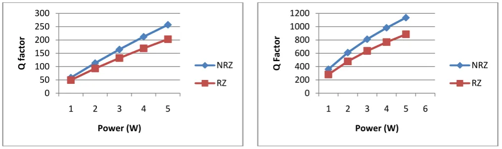
[image:3.595.304.550.457.597.2]Fig. gVariation of Q factor with respect to power (NRZ and RZ)
From the fig g for a range upto 1km the quality factor of NRZ is better than RZ.
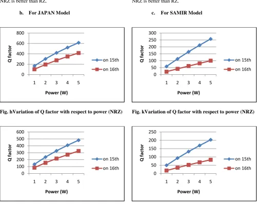
[image:4.595.47.549.259.657.2]b. For JAPAN Model
Fig. hVariation of Q factor with respect to power (NRZ)
Fig. iVariation of Q factor with respect to power (RZ)
Fig. jVariation of Q factor with respect to power (NRZ and RZ)
From the fig j for a range upto 1km the quality factor of NRZ is better than RZ.
c. For SAMIR Model
Fig. kVariation of Q factor with respect to power (NRZ)
Fig. lVariation of Q factor with respect to power (RZ) 0
200 400 600 800 1000
1 2 3 4 5
Q
fac
to
r
Power (W)
NRZ
RZ
0 200 400 600 800
1 2 3 4 5
Q
fact
o
r
Power (W)
on 15th
on 16th
0 100 200 300 400 500 600
1 2 3 4 5
Q
fact
o
r
Power (W)
on 15th
on 16th
0 200 400 600 800
1 2 3 4 5
Q
fac
to
r
Power (W)
NRZ
RZ
0 50 100 150 200 250 300
1 2 3 4 5
Q
fact
o
r
Power (W)
on 15th
on 16th
0 50 100 150 200 250
1 2 3 4 5
Q
fact
o
r
Power (W)
on 15th
International Journal of Innovative Technology and Exploring Engineering (IJITEE) ISSN: 2278-3075, Volume-8 Issue-6, April 2019
Fig. mVariation of Q factor with respect to power (NRZ and RZ)
From the fig m for a range upto 1km the quality factor of NRZ is better than RZ.
[image:5.595.45.290.283.459.2]d. For SURIZA Model
[image:5.595.303.551.357.505.2]Fig. nVariation of Q factor with respect to power (NRZ)
Fig. oVariation of Q factor with respect to power (RZ)
Fig. pVariation of Q factor with respect to power (NRZ and RZ)
From the fig j for a range upto 1km the quality factor of NRZ is better than RZ.
e. For all Models
[image:5.595.44.289.503.650.2]For different models the comparison of Q factor and Power is shown in Fig q from that we can say that Suriza model has better Q factor than the remaining models.
Fig. qVariation of Q factor with respect to power (For all Models-NRZ)
Fig. rVariation of Q factor with respect to power (For all Models-RZ)
0 50 100 150 200 250 300
1 2 3 4 5
Q
fac
to
r
Power (W)
NRZ
RZ
0 200 400 600 800 1000 1200
1 2 3 4 5
Q
Fact
o
r
Power (W)
on 15th
on 16th
0 200 400 600 800 1000
1 2 3 4 5
Q
Fact
o
r
Power (W)
on 15th
on 16th
0 200 400 600 800 1000 1200
1 2 3 4 5 6
Q
Fact
o
r
Power (W)
NRZ
RZ
0 200 400 600 800 1000 1200
1 2 3 4 5
Q
Fct
o
r
Power (W)
Ac at mm/hr
Aj at mm/hr
Asa at mm/hr
Asu at mm/hr
0 200 400 600 800 1000
1 2 3 4 5
Q
Fact
o
r
Power (W)
Ac at mm/hr
Aj at mm/hr
Asa at mm/hr
[image:5.595.302.550.547.696.2]From the Fig r and q we can say that the quality factor obtained for NRZ for different models is better than RZ for a range of 1 km.
VI. CONCLUSION
These results are compared during higher rain intensities and lower rain intensities on two different days. The results state that the variation of quality factor with respect power changes more for Suriza model when compared with the other models. So, for tropical regions we can use Suriza model as it gives better quality factor and for non-tropical and sub-tropical regions we can go for Carbonneau model. Overall for ranges like 1to 5 km we can clearly say that NRZ is better than RZ.
BIBLIOGRAPHY
1. Al-gailani, Samir A, et al. “Determination of rain attenuation parameters for free space optical link in tropical rain.” Optik-international journal for light and Electron Optical 125.4 (2014): 1575-1578.
2. Kleine-ostmann, Thomas and Tadaonagatsuna. “A review on Tera hertz communications research.” Journal of Infrared, Millimeter, and Terahertz Waves .32.2 (2011): 143-171.
3. Al-Gailani, S. A, A. B. Mohammad and R. Q. Shaddad. “Enhancement of free space optical links in heavy rain attenuation using multiple beam concepts.” Optik-international journal for light and electron optics 124.21 (2013): 4798-4801.
4. Immadi, Govardhani, et al. "Estimating the Performance of Free Space Optical Link under Adverse Weather Conditions by Using Various Models." Wireless Personal Communications 103.2 (2018): 1603-1613. 5. Luo, Yi, Wan-xia Huang, and Zi-yi Luo. "Attenuation of terahertz transmission through rain."Optoelectronics Letters 8.4 (2012): 310-313. 6. priyankasharma, and Mrs. Himalisarangal. "Performance evaluation of multiple transceivers FSO for different weather conditions." International Journal of Signal Processing, Image Processing and Pattern Recognition 8.12 (2015): 149-156.
7. Sony. K. Modelling the systems for improvised performance in FSO Networks, Journal of advanced research in dynamical and control systems, Volume 9,Issue Special Issue 14,2017,Pages 2627-2636. 8. K. Sony, “Propagation Studies in Free Space Using RZ and NRZ Optical
Links Under Atmospheric Turbulence” International Journal of Engineering & Technology, Vol 7(3.27) (2018) 627-630.
9. Noor, Nur Haedzerin Md, Ahmed WathikNaji, and Wajdi Al-Khateeb. "Performance analysis of a free space optics link with multiple transmitters/receivers." IIUM Engineering Journal13.1 (2012). 10. Zabidi, Suriza Ahmad, et al. "Analysis of rain effects on terrestrial free
space optics based on data measured in tropical climate." IIUM Engineering Journal 12.5 (2011).
11. Immadi, G., et al. "Estimation of Ku band satellite signal propagation impairment due to rain in tropical environment using ITU-R." International Journal of Applied Engineering Research 9.20 (2014): 7149-7168.
AUTHORSPROFILE
K. Sony is pursuing PhD degree in K L University, Vijayawadain the faculty of Electronics and Communication Engineering, specialized in Optical Communication. She received her Master of Engineering Degreein Laser and Electro optical engineering fromAnna University,Chennai. Her present affiliation is with K LUniversity since 2012,Vijayawada designated as Assistant professor in ECE. Her research interests are Optical Communication and Free Space Optics.
L. Sreekaris pursuing B.Tech degree in K L University, Vijayawadain the department of Electronics and Communication Engineering; His areas of interest include Free Space Optics and Optical communication.
Y. Sri Krishnais pursuing B.Tech degree in K L University, Vijayawadain the department of Electronics and Communication Engineering; His areas of interest include Free Space Optics and Optical communication.